EP0770535B1 - Stapelbarer Transportwagen - Google Patents
Stapelbarer Transportwagen Download PDFInfo
- Publication number
- EP0770535B1 EP0770535B1 EP96116000A EP96116000A EP0770535B1 EP 0770535 B1 EP0770535 B1 EP 0770535B1 EP 96116000 A EP96116000 A EP 96116000A EP 96116000 A EP96116000 A EP 96116000A EP 0770535 B1 EP0770535 B1 EP 0770535B1
- Authority
- EP
- European Patent Office
- Prior art keywords
- frame
- running gear
- gear frame
- transport trolley
- rocker
- Prior art date
- Legal status (The legal status is an assumption and is not a legal conclusion. Google has not performed a legal analysis and makes no representation as to the accuracy of the status listed.)
- Expired - Lifetime
Links
- 235000004443 Ricinus communis Nutrition 0.000 abstract description 34
- 240000000528 Ricinus communis Species 0.000 abstract description 17
- 239000000725 suspension Substances 0.000 abstract 1
- 230000001419 dependent effect Effects 0.000 description 1
- 239000002184 metal Substances 0.000 description 1
- 230000036316 preload Effects 0.000 description 1
Images
Classifications
-
- B—PERFORMING OPERATIONS; TRANSPORTING
- B62—LAND VEHICLES FOR TRAVELLING OTHERWISE THAN ON RAILS
- B62B—HAND-PROPELLED VEHICLES, e.g. HAND CARTS OR PERAMBULATORS; SLEDGES
- B62B3/00—Hand carts having more than one axis carrying transport wheels; Steering devices therefor; Equipment therefor
- B62B3/008—Hand carts having more than one axis carrying transport wheels; Steering devices therefor; Equipment therefor having more than two axes
-
- B—PERFORMING OPERATIONS; TRANSPORTING
- B62—LAND VEHICLES FOR TRAVELLING OTHERWISE THAN ON RAILS
- B62B—HAND-PROPELLED VEHICLES, e.g. HAND CARTS OR PERAMBULATORS; SLEDGES
- B62B3/00—Hand carts having more than one axis carrying transport wheels; Steering devices therefor; Equipment therefor
- B62B3/14—Hand carts having more than one axis carrying transport wheels; Steering devices therefor; Equipment therefor characterised by provisions for nesting or stacking, e.g. shopping trolleys
- B62B3/1476—Hand carts having more than one axis carrying transport wheels; Steering devices therefor; Equipment therefor characterised by provisions for nesting or stacking, e.g. shopping trolleys the main load support being a platform
-
- B—PERFORMING OPERATIONS; TRANSPORTING
- B62—LAND VEHICLES FOR TRAVELLING OTHERWISE THAN ON RAILS
- B62B—HAND-PROPELLED VEHICLES, e.g. HAND CARTS OR PERAMBULATORS; SLEDGES
- B62B3/00—Hand carts having more than one axis carrying transport wheels; Steering devices therefor; Equipment therefor
- B62B3/14—Hand carts having more than one axis carrying transport wheels; Steering devices therefor; Equipment therefor characterised by provisions for nesting or stacking, e.g. shopping trolleys
- B62B3/1492—Wheel arrangements
-
- B—PERFORMING OPERATIONS; TRANSPORTING
- B62—LAND VEHICLES FOR TRAVELLING OTHERWISE THAN ON RAILS
- B62B—HAND-PROPELLED VEHICLES, e.g. HAND CARTS OR PERAMBULATORS; SLEDGES
- B62B2301/00—Wheel arrangements; Steering; Stability; Wheel suspension
- B62B2301/08—Wheel arrangements; Steering; Stability; Wheel suspension comprising additional wheels to increase stability
Definitions
- the present invention relates to a stackable Transport trolley with a chassis that has a chassis frame, four castors and at least one between these fixed castor, with a shelf and one on the back Sliding device, the at least one Fixed castor on an articulated on the chassis frame suspended support frame from the by the castors spanned level is stored raised.
- Such a trolley is from the European Patent 0352647 known. It supports the chassis frame directly on the four Swivel castors. That's on the front of the chassis frame Support frame for the fixed castor around a horizontal, Axis extending transversely to the direction of travel articulated. It is also frontal a lifting device is provided on the chassis frame, which when stacking two transport trolleys Fixed castor support frame of the one in advance Transport trolley lifts and in this way the fixed castor of the respective preceding trolley out of contact with the ground. With a stack of several well-known transport trolleys only has that Fixed castor of the rearmost trolley contacting the ground.
- the known transport trolley has several disadvantages two of which are particularly noteworthy: For one, there are a pile of dolly too move, always required two people, namely a person pushing the stack from behind, and another person holding the front end of the stack leads and a breakout of the wagons aside in Curves and on a sideways inclined surface prevented. Second, stacking two Dolly a considerable effort; because the fixed castor must, so that they break out too of a heavily loaded dolly reliably prevented by using a high force against the road be prestressed, and just this high prestressing force is when stacking two transport trolleys Raise the fixed castor of the front trolley overcome.
- the stacking required effort to reduce the preload fixed castor against the road this would be the case with one loaded with a heavy load Transport carriage whose guidance in curves and on surfaces sloping sideways are not guaranteed.
- the object of the present invention is to achieve this based on a generic transport carriage in the Way to improve that a stack of several Push cart pushed by a single person can be, at the same time stacking two Dolly should be facilitated.
- this object solved in that the front castors on one articulated to the chassis frame Rocker frames are arranged, the rear Section the support frame for the at least one Fixed castor forms and on which extends lengthways between the front casters and the minimum a fixed castor supports the chassis frame, and that on the chassis frame at least by the amount of Stacking depth behind the front of a spreader is provided, which in each case next rear dolly of a stack of front sections of the rocker frame and the chassis frame spreads with respect to each other.
- a essential feature of the trolley according to the invention is thus that the front castors are not are arranged directly on the chassis frame, but rather on an articulated with the chassis frame connected rocker frame.
- the chassis frame on the rocker frame in the longitudinal direction between the front casters and the supporting at least one fixed castor is the force with which the fixed roller is pressed against the road becomes dependent on the loading of the trolley.
- the at least one fixed castor thus strongly on the road pressed so that the trolley breaks out in curves and / or on sideways inclined roads is certainly excluded.
- the contact pressure of at least a fixed role on the road only slightly, so that stacking two transport trolleys with little effort is possible. Different from this for the stand the technology applies, but is used in the Invention when stacking two transport cars not the fixed castor of the front trolley raised, but rather that of each rear dolly.
- the invention stands out Transport trolleys from the state of the art also in this regard advantageous from when he arranged without a face Lifting device for the support frame needs. Because those of the known generic type Lifting device provided on the front of the trolley is particularly dangerous Damaged, for example by starting the Trolley against curbs or others Parking spaces are common obstacles.
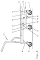
- the chassis 1 of the trolley includes one Chassis frame 2, two rear castors 3, two front castors 4 and one between the castors arranged fixed roller 5.
- the rear castors 3 by means of appropriate supports 6 arranged directly on the chassis frame 2.
- the front swivel castors 4, however, are in front on one Rocker frame 7 arranged around a horizontal, axis 8 extending transversely to the direction of travel is pivotally connected to the chassis frame 2.
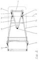
- the rocker frame 7 includes, as FIG. 2nd illustrates two V-shaped arranged to each other Spars. From each side rail of the chassis frame 2 jumps down a support 10 on which the assigned joint 11 to the corresponding Spar of the rocker frame 7 is arranged.
- a sliding device 12 provided on the rear is in a known manner with the chassis frame 2 connected. Is also in a known manner Storage rack 13 articulated with the chassis frame 2 connected, in such a way that the horizontal, transverse to the direction of travel Pivotal axis of the storage rack in the area thereof rear end is arranged.
- the two longitudinal spars of the chassis frame 2 are with a cross member 14 at the end connected. About the stacking depth of the trolleys (see FIG. 3) extends behind the cross member between the two longitudinal spars of the chassis frame 2 a cross strut 15. On the cross strut 15 is a wedge body 16 in its central region provided, the wedge tip 17 in the rear Direction extends.
- the wedge body 16 is how Fig. 1 illustrates bent from sheet metal.
- a cam 18 is provided on the front of the rocker undercarriage 7, that when stacking two trolleys with the Wedge body 16 cooperates. Its function results in detail from the explanation below 3.
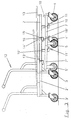
- the Direction of travel tapering chassis frame 2 'of rear trolley in the chassis frame 2 of the front trolley namely until the cross member 14 'of the rear trolley to the cross strut 15 of the front trolley triggers.
- the cross strut 15 acts on this Way as a stop defining the stack depth.
- the wedge body 16 penetrates the front Trolley in the space between the Cam 18 'and the cross member 14' of the rear Dolly.
- the wedge body spreads the front sections of the rocker frame 7 'and Chassis frame 2 'of the rear trolley regarding each other. For this he has a vertical Extent that is slightly larger than that Distance between the cross member 14 and the cam 18th for non-stacked trolleys.
- the horizontal distance of the articulation 11 between the rocker frame 7 and the chassis frame 2 of the front castors 4 is in the 1 to 3 illustrated embodiment of the trolley according to the invention Quarter of the distance between the front castors 4 and the fixed roller 5.
- the force applied is large enough to break out of the dolly in curves and on to prevent sideways sloping surfaces safely.
- On the other side is sufficient for such a dimensioning already a relatively small spread of the front sections of the chassis frame and Rocker frame when stacking around the fixed castor of the each rear trolley by a sufficient Measure to raise.
Landscapes
- Engineering & Computer Science (AREA)
- Chemical & Material Sciences (AREA)
- Combustion & Propulsion (AREA)
- Transportation (AREA)
- Mechanical Engineering (AREA)
- Handcart (AREA)
- Tea And Coffee (AREA)
- Iron Core Of Rotating Electric Machines (AREA)
- Manufacture Of Iron (AREA)
Description
- Fig. 1
- eine bevorzugte Ausführungsform des erfindungsgemäßen Transportwagens in Seitenansicht,
- Fig. 2
- eine Draufsicht auf den Transportwagen gemäß Fig. 1 und
- Fig. 3
- einen Stapel aus zwei ineinandergeschobenen Transportwagen gemäß Fig. 1.
Claims (6)
- Stapelbarer Transportwagen mit einem Fahrgestell (1), das einen Fahrgestellrahmen (2), vier Lenkrollen (3; 4) und wenigstens eine zwischen diesen angeordnete Bockrolle (5) aufweist, mit einer Ablagefläche sowie einer rückseitig angeordneten Schiebeeinrichtung (12), wobei die mindestens eine Bockrolle an einem gelenkig am Fahrgestellrahmen (2) aufgehängten Traggestell aus der durch die Lenkrollen (3, 4) aufgespannten Ebene heraus anhebbar gelagert ist,
dadurch gekennzeichnet,
daß die vorderen Lenkrollen (4) an einem gelenkig mit dem Fahrgestellrahmen (2) verbundenen Wippenrahmen (7) angeordnet sind, dessen hinterer Abschnitt das Traggestell für die mindestens eine Bockrolle (5) bildet und auf dem sich in Längsrichtung zwischen den vorderen Lenkrollen (4) und der mindestens einen Bockrolle (5) der Fahrgestellrahmen (2) abstützt, und daß am Fahrgestellrahmen (2) mindestens um das Maß der Stapeltiefe hinter dessen Stirnseite eine Spreizeinrichtung vorgesehen ist, die bei dem jeweils nächsten hinteren Transportwagen eines Stapels die vorderen Abschnitte des Wippenrahmens (7) und des Fahrgestellrahmens (2) bezüglich einander spreizt. - Stapelbarer Transportwagen nach Anspruch 1,
dadurch gekennzeichnet,
daß der horizontale Abstand der Gelenkverbindung (11) des Wippenrahmens (7) mit dem Fahrgestellrahmen (2) von den vorderen Lenkrollen (4) zwischen 20% und 50% des Abstandes zwischen den vorderen Lenkrollen (4) und der mindestens einen Bockrolle (5) beträgt. - Stapelbarer Transportwagen nach Anspruch 1,
dadurch gekennzeichnet,
daß die Spreizeinrichtung als Keilkörper (16) ausgebildet ist, dessen Keilspitze (17) in rückwärtige Richtung weist und der bei gestapelten Transportwagen den lichten Abstand zwischen den vorderen Enden des Fahrgestellrahmens (2') und des Wippenrahmens (7') des jeweils nächsten hinteren Transportwagens überbrückt. - Stapelbarer Transportwagen nach Anspruch 3,
dadurch gekennzeichnet,
daß der Keilkörper (16) an einer die Längsholme des Fahrgestellrahmens (2) verbindenden Querstrebe (15) angeordnet ist. - Stapelbarer Transportwagen nach Anspruch 1,
dadurch gekennzeichnet,
daß ein im Bereich seines rückwärtigen Endes gelenkig am Fahrgestellrahmen (2) angelenkter Ablagerost (13) vorgesehen ist. - Stapelbarer Transportwagen nach Anspruch 3,
dadurch gekennzeichnet,
daß zwei Keilkörper vorgesehen sind, welche innen an den Längsholmen des Fahrgestellrahmens (2) angeordnet sind.
Priority Applications (1)
| Application Number | Priority Date | Filing Date | Title |
|---|---|---|---|
| DE29622676U DE29622676U1 (de) | 1996-10-05 | 1996-10-05 | Stapelbarer Transportwagen |
Applications Claiming Priority (2)
| Application Number | Priority Date | Filing Date | Title |
|---|---|---|---|
| DE29516945U DE29516945U1 (de) | 1995-10-24 | 1995-10-24 | Stapelbarer Transportwagen |
| DE29516945U | 1995-10-24 |
Publications (2)
| Publication Number | Publication Date |
|---|---|
| EP0770535A1 EP0770535A1 (de) | 1997-05-02 |
| EP0770535B1 true EP0770535B1 (de) | 1999-04-21 |
Family
ID=8014613
Family Applications (1)
| Application Number | Title | Priority Date | Filing Date |
|---|---|---|---|
| EP96116000A Expired - Lifetime EP0770535B1 (de) | 1995-10-24 | 1996-10-05 | Stapelbarer Transportwagen |
Country Status (3)
| Country | Link |
|---|---|
| EP (1) | EP0770535B1 (de) |
| AT (1) | ATE179130T1 (de) |
| DE (2) | DE29516945U1 (de) |
Cited By (2)
| Publication number | Priority date | Publication date | Assignee | Title |
|---|---|---|---|---|
| DE102016101490A1 (de) | 2016-01-28 | 2017-08-03 | Wanzl Metallwarenfabrik Gmbh | Transportgerät |
| US11008034B2 (en) | 2017-01-03 | 2021-05-18 | Innovation Lab, LLC | Child medical transport apparatus, assembly and method thereof |
Families Citing this family (4)
| Publication number | Priority date | Publication date | Assignee | Title |
|---|---|---|---|---|
| DE29712800U1 (de) | 1997-07-19 | 1997-09-18 | Wanzl Metallwarenfabrik Gmbh, 89340 Leipheim | Stapelbarer Transportwagen |
| DE10305194A1 (de) | 2003-01-07 | 2004-07-15 | Brüder Siegel GmbH & Co KG Draht- und Metallwarenfabrik | Stapelbarer Transportwagen |
| WO2011017735A1 (en) * | 2009-08-11 | 2011-02-17 | Industrious Design Pty Ltd | Hand trolley |
| DE102011000916A1 (de) * | 2011-02-24 | 2012-08-30 | Dr. Ing. H.C. F. Porsche Aktiengesellschaft | Transportwagen |
Family Cites Families (2)
| Publication number | Priority date | Publication date | Assignee | Title |
|---|---|---|---|---|
| FR1574237A (de) * | 1968-05-30 | 1969-07-11 | ||
| DE3825597A1 (de) | 1988-07-28 | 1990-02-01 | Wanzl Metallwarenfabrik Kg | Stapelbarer transportwagen |
-
1995
- 1995-10-24 DE DE29516945U patent/DE29516945U1/de not_active Expired - Lifetime
-
1996
- 1996-10-05 DE DE59601702T patent/DE59601702D1/de not_active Expired - Lifetime
- 1996-10-05 EP EP96116000A patent/EP0770535B1/de not_active Expired - Lifetime
- 1996-10-05 AT AT96116000T patent/ATE179130T1/de not_active IP Right Cessation
Cited By (3)
| Publication number | Priority date | Publication date | Assignee | Title |
|---|---|---|---|---|
| DE102016101490A1 (de) | 2016-01-28 | 2017-08-03 | Wanzl Metallwarenfabrik Gmbh | Transportgerät |
| EP3202636A1 (de) | 2016-01-28 | 2017-08-09 | Wanzl Metallwarenfabrik GmbH | Transportgerät |
| US11008034B2 (en) | 2017-01-03 | 2021-05-18 | Innovation Lab, LLC | Child medical transport apparatus, assembly and method thereof |
Also Published As
| Publication number | Publication date |
|---|---|
| DE59601702D1 (de) | 1999-05-27 |
| EP0770535A1 (de) | 1997-05-02 |
| ATE179130T1 (de) | 1999-05-15 |
| DE29516945U1 (de) | 1996-02-15 |
Similar Documents
| Publication | Publication Date | Title |
|---|---|---|
| DE3825597A1 (de) | Stapelbarer transportwagen | |
| DE8523747U1 (de) | Transportwagen, insbesondere für die Kundschaft in Selbstbedienungsläden | |
| DE2449815A1 (de) | Vorrichtung zum anheben von fahrzeugen | |
| DE2854296C2 (de) | ||
| EP0152764A2 (de) | Arbeitsweise zum Verladen eines Flurförderzeuges sowie Stützwagen dafür | |
| EP0770535B1 (de) | Stapelbarer Transportwagen | |
| EP0569988B1 (de) | Transportkarre für unterfahrbare Gegenstände | |
| EP2439125A2 (de) | Fahrgestell für einen stapelbaren Einkaufswagen | |
| EP0905004B1 (de) | Stapelbarer Einkaufswagen | |
| EP0927676B1 (de) | Stapelbarer Transportwagen | |
| EP0593905B1 (de) | Von Hand bewegbarer Transportwagen | |
| DE3444278C2 (de) | Stapelbarer Einkaufswagen | |
| DE3710757A1 (de) | Gabelhubwagen | |
| DE9315976U1 (de) | Hub- und Transportkarre für Paletten | |
| EP0891912A1 (de) | Stapelbarer Transportwagen | |
| DE8904428U1 (de) | Stapelbarer Einkaufswagen | |
| EP3354536B1 (de) | Stapelbarer einkaufswagen | |
| DE29622676U1 (de) | Stapelbarer Transportwagen | |
| DE10039715B4 (de) | Schubgepäckwagen | |
| DE29520056U1 (de) | Stapelbarer Transportwagen | |
| DE29518266U1 (de) | Hubfahrzeug zum Anheben, Transportieren und Absenken von Transportgut | |
| DE7917706U1 (de) | Transportwagen | |
| DE4217944A1 (de) | Transportkarre für unterfahrbare Gegenstände | |
| DE1252588B (de) | ||
| EP1200299A1 (de) | Transportwagen zum befördern von gepäck |
Legal Events
| Date | Code | Title | Description |
|---|---|---|---|
| PUAI | Public reference made under article 153(3) epc to a published international application that has entered the european phase |
Free format text: ORIGINAL CODE: 0009012 |
|
| AK | Designated contracting states |
Kind code of ref document: A1 Designated state(s): AT BE CH DE ES FR GB IT LI LU NL |
|
| 17P | Request for examination filed |
Effective date: 19970507 |
|
| GRAG | Despatch of communication of intention to grant |
Free format text: ORIGINAL CODE: EPIDOS AGRA |
|
| GRAG | Despatch of communication of intention to grant |
Free format text: ORIGINAL CODE: EPIDOS AGRA |
|
| GRAH | Despatch of communication of intention to grant a patent |
Free format text: ORIGINAL CODE: EPIDOS IGRA |
|
| 17Q | First examination report despatched |
Effective date: 19980925 |
|
| GRAH | Despatch of communication of intention to grant a patent |
Free format text: ORIGINAL CODE: EPIDOS IGRA |
|
| GRAA | (expected) grant |
Free format text: ORIGINAL CODE: 0009210 |
|
| AK | Designated contracting states |
Kind code of ref document: B1 Designated state(s): AT BE CH DE ES FR GB IT LI LU NL |
|
| PG25 | Lapsed in a contracting state [announced via postgrant information from national office to epo] |
Ref country code: NL Free format text: LAPSE BECAUSE OF FAILURE TO SUBMIT A TRANSLATION OF THE DESCRIPTION OR TO PAY THE FEE WITHIN THE PRESCRIBED TIME-LIMIT Effective date: 19990421 Ref country code: ES Free format text: THE PATENT HAS BEEN ANNULLED BY A DECISION OF A NATIONAL AUTHORITY Effective date: 19990421 |
|
| REF | Corresponds to: |
Ref document number: 179130 Country of ref document: AT Date of ref document: 19990515 Kind code of ref document: T |
|
| REG | Reference to a national code |
Ref country code: CH Ref legal event code: EP |
|
| ET | Fr: translation filed | ||
| REF | Corresponds to: |
Ref document number: 59601702 Country of ref document: DE Date of ref document: 19990527 |
|
| GBT | Gb: translation of ep patent filed (gb section 77(6)(a)/1977) |
Effective date: 19990715 |
|
| PG25 | Lapsed in a contracting state [announced via postgrant information from national office to epo] |
Ref country code: LU Free format text: LAPSE BECAUSE OF NON-PAYMENT OF DUE FEES Effective date: 19991005 |
|
| PG25 | Lapsed in a contracting state [announced via postgrant information from national office to epo] |
Ref country code: BE Free format text: LAPSE BECAUSE OF NON-PAYMENT OF DUE FEES Effective date: 19991031 |
|
| PLBE | No opposition filed within time limit |
Free format text: ORIGINAL CODE: 0009261 |
|
| STAA | Information on the status of an ep patent application or granted ep patent |
Free format text: STATUS: NO OPPOSITION FILED WITHIN TIME LIMIT |
|
| 26N | No opposition filed | ||
| BERE | Be: lapsed |
Owner name: BRUDER SIEGEL G.M.B.H. + CO. K.G. DRAHT- UND META Effective date: 19991031 |
|
| PG25 | Lapsed in a contracting state [announced via postgrant information from national office to epo] |
Ref country code: LI Free format text: LAPSE BECAUSE OF NON-PAYMENT OF DUE FEES Effective date: 20001031 Ref country code: CH Free format text: LAPSE BECAUSE OF NON-PAYMENT OF DUE FEES Effective date: 20001031 |
|
| REG | Reference to a national code |
Ref country code: CH Ref legal event code: PL |
|
| REG | Reference to a national code |
Ref country code: GB Ref legal event code: IF02 |
|
| PGFP | Annual fee paid to national office [announced via postgrant information from national office to epo] |
Ref country code: IT Payment date: 20061031 Year of fee payment: 11 |
|
| PGFP | Annual fee paid to national office [announced via postgrant information from national office to epo] |
Ref country code: AT Payment date: 20070430 Year of fee payment: 11 |
|
| PGFP | Annual fee paid to national office [announced via postgrant information from national office to epo] |
Ref country code: GB Payment date: 20070427 Year of fee payment: 11 |
|
| GBPC | Gb: european patent ceased through non-payment of renewal fee |
Effective date: 20071005 |
|
| PG25 | Lapsed in a contracting state [announced via postgrant information from national office to epo] |
Ref country code: AT Free format text: LAPSE BECAUSE OF NON-PAYMENT OF DUE FEES Effective date: 20071005 |
|
| PG25 | Lapsed in a contracting state [announced via postgrant information from national office to epo] |
Ref country code: GB Free format text: LAPSE BECAUSE OF NON-PAYMENT OF DUE FEES Effective date: 20071005 |
|
| PGFP | Annual fee paid to national office [announced via postgrant information from national office to epo] |
Ref country code: FR Payment date: 20081021 Year of fee payment: 13 |
|
| PG25 | Lapsed in a contracting state [announced via postgrant information from national office to epo] |
Ref country code: IT Free format text: LAPSE BECAUSE OF NON-PAYMENT OF DUE FEES Effective date: 20071005 |
|
| REG | Reference to a national code |
Ref country code: FR Ref legal event code: ST Effective date: 20100630 |
|
| PG25 | Lapsed in a contracting state [announced via postgrant information from national office to epo] |
Ref country code: FR Free format text: LAPSE BECAUSE OF NON-PAYMENT OF DUE FEES Effective date: 20091102 |
|
| PGFP | Annual fee paid to national office [announced via postgrant information from national office to epo] |
Ref country code: DE Payment date: 20101031 Year of fee payment: 15 |
|
| PG25 | Lapsed in a contracting state [announced via postgrant information from national office to epo] |
Ref country code: DE Free format text: LAPSE BECAUSE OF NON-PAYMENT OF DUE FEES Effective date: 20130501 |
|
| REG | Reference to a national code |
Ref country code: DE Ref legal event code: R119 Ref document number: 59601702 Country of ref document: DE Effective date: 20130501 |