EP0769656B1 - Improvements in burners for water-heaters, bath-heathers or gas-fired boilers - Google Patents
Improvements in burners for water-heaters, bath-heathers or gas-fired boilers Download PDFInfo
- Publication number
- EP0769656B1 EP0769656B1 EP96402197A EP96402197A EP0769656B1 EP 0769656 B1 EP0769656 B1 EP 0769656B1 EP 96402197 A EP96402197 A EP 96402197A EP 96402197 A EP96402197 A EP 96402197A EP 0769656 B1 EP0769656 B1 EP 0769656B1
- Authority
- EP
- European Patent Office
- Prior art keywords
- flame
- burner
- venturi tube
- burner according
- atmospheric burner
- Prior art date
- Legal status (The legal status is an assumption and is not a legal conclusion. Google has not performed a legal analysis and makes no representation as to the accuracy of the status listed.)
- Expired - Lifetime
Links
Images
Classifications
-
- F—MECHANICAL ENGINEERING; LIGHTING; HEATING; WEAPONS; BLASTING
- F23—COMBUSTION APPARATUS; COMBUSTION PROCESSES
- F23D—BURNERS
- F23D14/00—Burners for combustion of a gas, e.g. of a gas stored under pressure as a liquid
- F23D14/46—Details, e.g. noise reduction means
- F23D14/72—Safety devices, e.g. operative in case of failure of gas supply
- F23D14/78—Cooling burner parts
-
- F—MECHANICAL ENGINEERING; LIGHTING; HEATING; WEAPONS; BLASTING
- F23—COMBUSTION APPARATUS; COMBUSTION PROCESSES
- F23D—BURNERS
- F23D14/00—Burners for combustion of a gas, e.g. of a gas stored under pressure as a liquid
- F23D14/02—Premix gas burners, i.e. in which gaseous fuel is mixed with combustion air upstream of the combustion zone
- F23D14/04—Premix gas burners, i.e. in which gaseous fuel is mixed with combustion air upstream of the combustion zone induction type, e.g. Bunsen burner
- F23D14/045—Premix gas burners, i.e. in which gaseous fuel is mixed with combustion air upstream of the combustion zone induction type, e.g. Bunsen burner with a plurality of burner bars assembled together, e.g. in a grid-like arrangement
-
- F—MECHANICAL ENGINEERING; LIGHTING; HEATING; WEAPONS; BLASTING
- F23—COMBUSTION APPARATUS; COMBUSTION PROCESSES
- F23D—BURNERS
- F23D14/00—Burners for combustion of a gas, e.g. of a gas stored under pressure as a liquid
- F23D14/02—Premix gas burners, i.e. in which gaseous fuel is mixed with combustion air upstream of the combustion zone
- F23D14/04—Premix gas burners, i.e. in which gaseous fuel is mixed with combustion air upstream of the combustion zone induction type, e.g. Bunsen burner
- F23D14/10—Premix gas burners, i.e. in which gaseous fuel is mixed with combustion air upstream of the combustion zone induction type, e.g. Bunsen burner with elongated tubular burner head
-
- F—MECHANICAL ENGINEERING; LIGHTING; HEATING; WEAPONS; BLASTING
- F23—COMBUSTION APPARATUS; COMBUSTION PROCESSES
- F23D—BURNERS
- F23D14/00—Burners for combustion of a gas, e.g. of a gas stored under pressure as a liquid
- F23D14/46—Details, e.g. noise reduction means
Definitions
- the present invention relates to a device intended to equip boilers with gas supply. It relates more particularly to the burners fitted to the water heaters, bath heaters and gas boilers and which realize within a room, the combustion natural or assisted by a premix consisting of oxidizer, in particular air, and a fuel, especially of the gas type.
- the burner, object of the invention seeks to achieve at the times a double objective, on the one hand a decrease in pollutant emissions from the flames, and secondly a flame stabilization, while respecting optimal physical and mechanical conditions of the combustion.
- the shape and the reduced size of the spout require the same overall power delivered to increase the number nozzles and therefore the number of air injection points primary. They also make it possible to develop burners variable power from an assembly by juxtaposition of different batteries of spouts burners placed in parallel or staggered.
- the burner burners thus designed also have orifices linked together by a network of conduits which make possible the circulation of a heat transfer fluid for cooling the whole.
- Known burner devices include generally a battery of ramps obtained by stamping of a metal sheet and at the top of which the combustion of the fuel is carried out, in particular gas, within an oxidizer, especially air.
- a atmospheric burner made up of modules arranged in a succession of parallel rows, each module comprising a venturi tube, feeding in premix air / gas a chamber which is covered by an outlet of flame, said chamber also having a zone of pinch between the flame outlet and the venturi tube, this burner being furthermore traversed by orifices.
- the burner arrangements are not optimal for combustion control, mainly in terms of flame stability and of its homogeneity. In addition, they most often require to work with a low primary air rate well lower than the rate corresponding to stoichiometry.
- the present invention therefore aims to remedy these disadvantages, by proposing a burner device such that the secondary air arrives in a way that minimizes the time required for complete combustion of the mixture gaseous present at the burner outlet, this mixture being composed in adequate proportion of a fuel to ignite and primary combustion air to it associated, allowing to stabilize and hang the flames at the burner outlet.
- the assembly of a plurality of burners according to the invention allows the user flexibility functioning, because it can, for the same useful volume, choose and assemble the number of burners, depending of the requested heating power.
- the atmospheric burner, object of the invention comprising a plurality of modules arranged in a succession of parallel rows made up of aligned and / or staggered tubes, each module comprising at least one venturi tube, supplying premix air-gas at least one room that is covered by a flame outlet with a rounded profile, said chamber additionally having a nip between the flame outlet and venturi tube, venturi tubes being formed by the assembly of half-shells having a plurality of orifices through which conduits are arranged, said orifices being formed so that they are facing each other and cooperating between them when assembling the two half-shells.
- the characteristics of the burner according to the invention allow to obtain a reduction significant NOx levels.
- the front of this mixing chamber is intended to receive in particular, by nesting, by slide, preferably relatively waterproof, a cover 11 made of a material compatible with the proximity to the flame, for example stainless steel, and provided with orifices 12.
- This cover 11 constitutes the flame outlet and has an upper surface of which the profile is rounded.
- an output will preferably be used flame of cylindrical shape because it allows to obtain a stable flame, "off the hook", thus generating little pressure drop on the air-gas mixture flow and a low temperature reducing NOx levels, by the low heat exchange between an "off the hook" flame and the upper surface of the beak.
- the orifices 12 arranged uniformly on the flame outlet 11 cylindrical consist of 13 transverse slots to the longitudinal axis of the flame outlet.
- the cylindrical flame outlet has at its top a strip of material 14 in order to split the slots in half according to a quadrant.
- the geometrical configuration, the distribution, the dimensions of the slots 13 are adjusted according to flame stability and the desired surface power.
- the flame outlet has at its zones of contact with the side wall venturi tube 15 allowing interlocking according to the interior or according the outside of the wall of the venturi tube, these walls 15 according to a second embodiment can be folded in order to conform slides.
- the ends 16 of the side walls 15 of the flame outlet 11, in a mounting mode by interlocking, have a cutout 16, so as to making flexible legs 17; these last both improve the mechanical strength of the assembly, and the exchange of calories with the medium surrounding.
- the quality of the thermal contact between the flame outlet and the body of the spout will be compatible with the flow thermal to evacuate.
- the flame outlet may be in steel stainless tin-plated so that during operation, the tin film ensures soldering continuous and homogeneous between the flame outlet and the spout burner.
- the use of tin is only given as an example, and this quality of thermal bond that appears independently when the burner works, that is to say by simplifying the assembly process in manufacturing, can be obtained with any other brazing compatible with copper and stainless steel and whose melting point is lower than the temperature reached by the outlet of flame when the burner is operating. She may be also obtained with alloys with melting point higher, but this complicates the manufacturing process burner burners.
- venturi tube 1 provided with an outlet cylindrical flame 11, as described above, ensures a primary air ventilation rate, preferably slightly higher than that corresponding to a stoichiometric mixture.
- the burner, object of the invention is obtained by the juxtaposition of a plurality of modules composed of minus a venturi tube, assembly being carried out by through the joint planes 18, formed during the joining of the two half-shells 2, 3.
- each simple module provided of a venturi tube keeps its own mixing chamber 9 and its own flame outlet 11, and according to a second variant (not shown), in an application consisting of a double module, the two venturi tubes 1 pool each of their mixing chamber 9 in upper part and in the area close to the axis of central symmetry, the flame outputs 11 are also joined together to form a single cover and also have a rounded profile.
- the half-shells have a plurality of orifices 19 came during the stamping operation, these orifices cooperate with each other during the juxtaposition of two 2-3 half-shells in module.
- the invention authorizes the development of burners obtained by the association of a plurality of modules, these being arranged in a succession of rows parallel tubes aligned and / or staggered.
- conduits 20 for improve the mechanical strength of the assembly, we have conduits 20 in the various orifices 19 in look. Depending on the use regimes, we restores circulation of heat transfer fluid within these conduits.
- the invention described above offers multiple advantages, such as in particular obtaining a flame combustion primary near stoichiometry whose contact area with the exit surface is weak and therefore not very conducive to heating, and secondary flame of over-stoichiometric combustion in which is carried out the oxidation of products from primary combustion.
- the present invention is not not limited to the embodiments described and shown above, but that it includes all variants.
- the second tubular part 7 of the burner according to the embodiment described above can be integrated into the mixing chamber 9, constituting thus a conical zone with elliptical section and surface variable.
- said conical section section elliptical and variable surface has a length representing 70% of the total length of the burner, measured along the flow line of the air-gas mixture.
Landscapes
- Engineering & Computer Science (AREA)
- Chemical & Material Sciences (AREA)
- Combustion & Propulsion (AREA)
- Mechanical Engineering (AREA)
- General Engineering & Computer Science (AREA)
- Gas Burners (AREA)
- Details Of Fluid Heaters (AREA)
- Control For Baths (AREA)
- Heat-Pump Type And Storage Water Heaters (AREA)
- Percussion Or Vibration Massage (AREA)
Abstract
Description
La présente invention est relative à un dispositif destiné à équiper les chaudières à alimentation à gaz. Elle vise plus particulièrement les brûleurs équipant les chauffe-eau, les chauffe-bains et les chaudières à gaz et qui réalisent au sein d'une chambre, la combustion naturelle ou assistée d'un pré-mélange constitué d'un comburant, notamment de l'air, et d'un carburant, notamment du type gaz.The present invention relates to a device intended to equip boilers with gas supply. It relates more particularly to the burners fitted to the water heaters, bath heaters and gas boilers and which realize within a room, the combustion natural or assisted by a premix consisting of oxidizer, in particular air, and a fuel, especially of the gas type.
Le brûleur, objet de l'invention, cherche à réaliser à la fois un double objectif, d'une part une diminution des émissions de polluants des flammes, et d'autre part une stabilisation des flammes, tout en respectant les conditions optimales physiques et mécaniques de la combustion.The burner, object of the invention, seeks to achieve at the times a double objective, on the one hand a decrease in pollutant emissions from the flames, and secondly a flame stabilization, while respecting optimal physical and mechanical conditions of the combustion.
Il vise également à être de conception modulaire de façon à pouvoir optimiser du point de vue économique les couples - encombrement/puissance - et - charge calorifique/émission de polluants -. Ainsi, le brûleur atmosphérique dans son dimensionnement doit :
- garantir un écoulement et un entraínement optimal des espèces gazeuses, comburant et carburant, en particulier en garantissant une bonne homogénéité du mélange air/gaz et de la vitesse de sortie sur toute la surface de la sortie de flamme ;
- diminuer la température de flamme, directement liée à la formation d'oxydes d'azote, d'une part en minimisant les pertes de charges hydrauliques, ce qui favorise l'entraínement d'air, et d'autre part en faisant en sorte que le corps du bec serve de radiateur thermique pour la sortie de flamme afin que cette dernière s'échauffe aussi peu que possible.
- guarantee an optimal flow and entrainment of gaseous, oxidizing and fuel species, in particular by guaranteeing a good homogeneity of the air / gas mixture and the exit speed over the entire surface of the flame exit;
- decrease the flame temperature, directly linked to the formation of nitrogen oxides, on the one hand by minimizing the hydraulic pressure losses, which favors the entrainment of air, and on the other hand by ensuring that the body of the spout acts as a heat radiator for the flame outlet so that the latter heats up as little as possible.
La forme et l'encombrement réduit du bec demandent pour une même puissance globale délivrée d'augmenter le nombre de becs et donc le nombre de points d'injection d'air primaire. Ils permettent en outre d'élaborer des brûleurs de puissance variable à partir d'un assemblage par juxtaposition de différentes batteries de becs de brûleurs placées en parallèle ou en quinconce.The shape and the reduced size of the spout require the same overall power delivered to increase the number nozzles and therefore the number of air injection points primary. They also make it possible to develop burners variable power from an assembly by juxtaposition of different batteries of spouts burners placed in parallel or staggered.
Les becs de brûleurs ainsi conçus disposent par ailleurs d'orifices reliés entre eux par un réseau de conduits qui rendent possible une circulation d'un fluide caloporteur pour le refroidissement de l'ensemble.The burner burners thus designed also have orifices linked together by a network of conduits which make possible the circulation of a heat transfer fluid for cooling the whole.
Les dispositifs de brûleurs connus comportent généralement une batterie de rampes obtenues par emboutissage d'une tôle métallique et au sommet desquelles on réalise la combustion du carburant, notamment du gaz, au sein d'un comburant, particulièrement de l'air.Known burner devices include generally a battery of ramps obtained by stamping of a metal sheet and at the top of which the combustion of the fuel is carried out, in particular gas, within an oxidizer, especially air.
On connaít notamment par le brevet GB-A- 2 262 336, un brûleur atmosphérique formé de modules disposés en une succession de rangées parallèles, chaque module comportant un tube venturi, alimentant en pré-mélange air/gaz une chambre qui est recouverte par une sortie de flamme, ladite chambre disposant en outre d'une zone de pincement entre la sortie de flamme et le tube venturi, ce brûleur étant en outre traversé d'orifices.We know in particular from GB-A-2 262 336, a atmospheric burner made up of modules arranged in a succession of parallel rows, each module comprising a venturi tube, feeding in premix air / gas a chamber which is covered by an outlet of flame, said chamber also having a zone of pinch between the flame outlet and the venturi tube, this burner being furthermore traversed by orifices.
On connaít par ailleurs, par le brevet EP-A-0 657 691, un brûleur obtenu par l'assemblage de deux demi-coquilles et conformant ainsi un module, ce module étant recouvert par une sortie de flamme, ce brûleur étant muni en outre d'orifices, ces orifices coopérant entre eux lors de l'assemblage des demi-coquilles.We also know, from patent EP-A-0 657 691, a burner obtained by assembling two half-shells and thus conforming a module, this module being covered by a flame outlet, this burner being further provided orifices, these orifices cooperating with each other during the assembly of the half-shells.
Néanmoins, les agencements de brûleurs ne sont pas optimaux pour la conduite de la combustion, principalement au niveau de la stabilité de la flamme et de son homogénéité. Ils obligent en outre le plus souvent à travailler avec un taux d'air primaire faible bien inférieur au taux correspondant à la stoechiométrie.However, the burner arrangements are not optimal for combustion control, mainly in terms of flame stability and of its homogeneity. In addition, they most often require to work with a low primary air rate well lower than the rate corresponding to stoichiometry.
La présente invention vise donc à remédier à ces inconvénients, en proposant un dispositif de brûleur tel que l'air secondaire arrive d'une façon qui minimise le temps nécessaire à la combustion complète du mélange gazeux présent en sortie du brûleur, ce mélange étant composé en proportion adéquate d'un combustible à enflammer et d'air primaire de combustion qui lui est associé, permettant ainsi de stabiliser et d'accrocher les flammes en sortie de brûleur.The present invention therefore aims to remedy these disadvantages, by proposing a burner device such that the secondary air arrives in a way that minimizes the time required for complete combustion of the mixture gaseous present at the burner outlet, this mixture being composed in adequate proportion of a fuel to ignite and primary combustion air to it associated, allowing to stabilize and hang the flames at the burner outlet.
De plus, l'assemblage d'une pluralité de brûleurs selon l'invention permet à l'utilisateur une souplesse de fonctionnement, car il peut, pour un même volume utile, choisir et assembler le nombre de brûleurs, en fonction de la puissance de chauffe demandée.In addition, the assembly of a plurality of burners according to the invention allows the user flexibility functioning, because it can, for the same useful volume, choose and assemble the number of burners, depending of the requested heating power.
A cet effet, le brûleur atmosphérique, objet de l'invention, comportant une pluralité de modules disposés en une succession de rangées parallèles constituées de tubes alignés et/ou en quinconce, chaque module comprenant au moins un tube venturi, alimentant en pré-mélange air-gaz au moins une chambre qui est recouverte par une sortie de flamme à profil arrondi, ladite chambre disposant en outre d'une zone de pincement entre la sortie de flamme et le tube venturi, les tubes venturi étant formés par l'assemblage de demi-coquilles comportant une pluralité d'orifices à travers lesquels sont disposés des conduits, lesdits orifices étant formés de telle sorte qu'ils sont en regard et qu'ils coopérent entre eux lors de l'assemblage des deux demi-coquilles.For this purpose, the atmospheric burner, object of the invention, comprising a plurality of modules arranged in a succession of parallel rows made up of aligned and / or staggered tubes, each module comprising at least one venturi tube, supplying premix air-gas at least one room that is covered by a flame outlet with a rounded profile, said chamber additionally having a nip between the flame outlet and venturi tube, venturi tubes being formed by the assembly of half-shells having a plurality of orifices through which conduits are arranged, said orifices being formed so that they are facing each other and cooperating between them when assembling the two half-shells.
Les caractéristiques du brûleur selon l'invention, tel que défini ci-dessus, permettent d'obtenir une réduction importante des taux de NOx. The characteristics of the burner according to the invention, such as defined above, allow to obtain a reduction significant NOx levels.
D'autres caractéristiques et avantages de la présente invention ressortiront de la description faite ci-après, en référence aux dessins annexés qui en illustrent un exemple de réalisation dépourvu de tout caractère limitatif. Sur les figures :
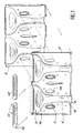
- la figure 1 est une vue en perspective et en éclaté, du brûleur selon l'invention ;
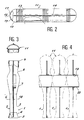
- la figure 2 est une vue en élévation frontale et en coupe, d'une sortie de flamme équipant le brûleur selon l'invention ;
- la figure 3 est une vue en élévation latérale et en coupe, du brûleur, objet de l'invention ;
- la figure 4 est une vue, en élévation latérale et en coupe, de l'assemblage d'une pluralité de brûleurs ;
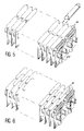
- la figure 5 est une vue en perspective de l'assemblage d'une pluralité de brûleurs selon un premier mode de réalisation ;
- la figure 6 est une vue en perspective de l'assemblage d'une pluralité de brûleurs selon un deuxième mode de réalisation.
- Figure 1 is a perspective and exploded view of the burner according to the invention;
- Figure 2 is a front elevational view in section, of a flame outlet fitted to the burner according to the invention;
- Figure 3 is a side elevational view in section, of the burner, object of the invention;
- FIG. 4 is a view, in side elevation and in section, of the assembly of a plurality of burners;
- Figure 5 is a perspective view of the assembly of a plurality of burners according to a first embodiment;
- Figure 6 is a perspective view of the assembly of a plurality of burners according to a second embodiment.
Selon un mode préféré de réalisation du brûleur, objet de l'invention, celui-ci comporte un tube venturi 1, obtenu par la réunion de deux demi-coquilles 2, 3 réalisées à partir de l'emboutissage d'une feuille métallique dont le coefficient de conduction thermique sera adapté au flux thermique qu'il est nécessaire d'évacuer pour avoir un refroidissement de la sortie de flamme en accord avec le taux de NOx recherché. Ainsi, pourra être employé selon le cas, du cuivre, de l'aluminium, de la tôle aluminée ou de l'acier inoxydable. Le tube venturi est de forme complexe, il se décompose de la manière suivante :
- en partie inférieure 4, une section annulaire convergente 5, devant être positionnée au-dessus de la nourrice d'injection,
- cette
section 5 est reliée à une première partie tubulaire 6, cylindrique ou faiblement conique et également convergente. Dans cet exemple de réalisation non limitatif, cettepartie 6 s'étend globalement sur un tiers de la demi-longueur de la partie tubulaire totale. Cette partie tubulaire a un diamètre dimensionné en fonction de la charge nominale d'utilisation du bec, préférentiellement selon un ratio supérieur ou égal à 15 mm/kW. - une deuxième partie tubulaire 7, connectée à la précédente 6, de longueur sensiblement égale dans cet exemple de réalisation non limitatif, conique mais divergente, et reliée,
- en partie supérieure 8, à une section beaucoup plus
évasée, formant chambre de
mélange 9 et dont la section droite transversale est sensiblement rectangulaire et présente également entre cette zone frontale et la zone de connexion avec la partie tubulaire 7, une zone depincement 10, selon un plan tranversal, de profil sensiblement ovoïde simple ou complexe.
- in the
lower part 4, a convergingannular section 5, to be positioned above the injection manifold, - this
section 5 is connected to a firsttubular part 6, cylindrical or slightly conical and also convergent. In this nonlimiting exemplary embodiment, thispart 6 generally extends over a third of the half-length of the total tubular part. This tubular part has a diameter dimensioned as a function of the nominal load of use of the spout, preferably according to a ratio greater than or equal to 15 mm / kW. - a second
tubular part 7, connected to the previous one 6, of substantially equal length in this nonlimiting embodiment, conical but divergent, and connected, - in the
upper part 8, with a much more flared section, forming themixing chamber 9 and the cross section of which is substantially rectangular and also has, between this front zone and the zone of connection with thetubular part 7, apinching zone 10, according to a transverse plane, of substantially simple or complex ovoid profile.
De préférence, on choisira les longueurs des différents éléments du brûleur, mesurées le long de la ligne d'écoulement du pré-mélange air-gaz selon la répartition ci-après :
- partie supérieure 8 (chambre de mélange 9) : 35 à 45 %,
- deuxième partie tubulaire 7 : 35 à 45 %,
- première partie tubulaire 6 : 5 à 25 %,
- partie inférieure 4 : 5 %.
- upper part 8 (mixing chamber 9): 35 to 45%,
- second tubular part 7: 35 to 45%,
- first tubular part 6: 5 to 25%,
- lower part 4: 5%.
La partie frontale de cette chambre de mélange est
destinée à recevoir notamment, par emboítement, par
glissière, de préférence relativement étanche, un
couvercle 11 réalisé dans un matériau compatible avec la
proximité de la flamme, par exemple en acier inoxydable,
et pourvu d'orifices 12. Ce couvercle 11 constitue la
sortie de flamme et présente une surface supérieure dont
le profil est arrondi.The front of this mixing chamber is
intended to receive in particular, by nesting, by
slide, preferably relatively waterproof, a
Selon l'invention, on utilisera de préférence une sortie de flamme de forme cylindrique car elle permet d'obtenir une flamme stable, "décrochée", générant donc peu de perte de charge sur l'écoulement du mélange air-gaz et une température faible réduisant les taux de NOx, de par le faible échange thermique entre une flamme "décrochée" et la surface supérieure du bec.According to the invention, an output will preferably be used flame of cylindrical shape because it allows to obtain a stable flame, "off the hook", thus generating little pressure drop on the air-gas mixture flow and a low temperature reducing NOx levels, by the low heat exchange between an "off the hook" flame and the upper surface of the beak.
Selon une caractéristique avantageuse de l'invention, les
orifices 12 disposés uniformément sur la sortie de flamme
11 cylindrique sont constitués de fentes 13 transversales
à l'axe longitudinal de la sortie de flamme.
Préférentiellement, la sortie de flamme cylindrique
présente en son sommet une bande de matière 14 afin de
séparer les fentes en deux selon un quadrant. Selon
l'invention, la configuration géométrique, la
répartition, les dimensions des fentes 13 sont ajustées
en fonction des exigences de stabilité des flammes et de
la puissance surfacique recherchée.According to an advantageous characteristic of the invention, the
La sortie de flamme dispose au niveau de ses zones de
contact avec le tube venturi de parois latérales 15
permettant un emboítement selon l'intérieur ou selon
l'extérieur de la paroi du tube venturi, ces parois 15
selon un deuxième mode de réalisation peuvent être pliées
afin de conformer des glissières.The flame outlet has at its zones of
contact with the side
Avantageusement, les extrémités 16 des parois latérales
15 de la sortie de flamme 11, dans un mode de montage par
emboítement, présentent une découpe 16, de manière à
réaliser des pattes flexibles 17 ; ces dernières
permettent à la fois d'améliorer la tenue mécanique de
l'assemblage, et l'échange des calories avec le milieu
environnant.Advantageously, the ends 16 of the
La qualité du contact thermique entre la sortie de flamme et le corps du bec, sera compatible avec le flux thermique à évacuer. Par exemple, en cas de flux maximum, donc de taux de NOx le plus faible, le corps du bec étant en cuivre, la sortie de flamme pourra être en acier inoxydable étamé de façon à ce qu'en cours de fonctionnement, la pellicule d'étain assure un brasage continu et homogène entre la sortie de flamme et le bec de brûleur. L'utilisation de l'étain n'est donnée qu'à titre d'exemple, et cette qualité de liaison thermique qui apparaít de façon autonome lorsque le brûleur fonctionne, c'est-à-dire en simplifiant au maximum le processus d'assemblage en fabrication, peut être obtenue avec toute autre brasure compatible avec le cuivre et l'acier inoxydable et dont le point de fusion est inférieur à la température atteinte par la sortie de flamme lorsque le brûleur fonctionne. Elle peut être obtenue également avec des alliages à point de fusion plus élevé, mais cela complique le mode de fabrication des becs de brûleur.The quality of the thermal contact between the flame outlet and the body of the spout, will be compatible with the flow thermal to evacuate. For example, in case of maximum flow, therefore the lowest NOx level, the body of the spout being in copper, the flame outlet may be in steel stainless tin-plated so that during operation, the tin film ensures soldering continuous and homogeneous between the flame outlet and the spout burner. The use of tin is only given as an example, and this quality of thermal bond that appears independently when the burner works, that is to say by simplifying the assembly process in manufacturing, can be obtained with any other brazing compatible with copper and stainless steel and whose melting point is lower than the temperature reached by the outlet of flame when the burner is operating. She may be also obtained with alloys with melting point higher, but this complicates the manufacturing process burner burners.
La configuration d'un tube venturi 1 pourvu d'une sortie
de flamme 11 cylindrique, telle que décrite précédemment,
assure un taux d'aération d'air primaire,
préférentiellement légèrement supérieur à celui
correspondant à un mélange stoechiométrique.The configuration of a
Le brûleur, objet de l'invention, est obtenu par la
juxtaposition d'une pluralité de modules composés d'au
moins un tube venturi, l'assemblage étant effectué par
l'intermédiaire des plans de joint 18, constitués lors de
la solidarisation des deux demi-coquilles 2, 3.The burner, object of the invention, is obtained by the
juxtaposition of a plurality of modules composed of
minus a venturi tube, assembly being carried out by
through the
Selon une première variante, chaque module simple muni
d'un tube venturi conserve sa propre chambre de mélange 9
et sa propre sortie de flamme 11, et selon une deuxième
variante (non représentée), dans une application
constituée d'un module double, les deux tubes venturi 1
mettent en commun chacune de leur chambre de mélange 9 en
partie supérieure et dans la zone proche de l'axe de
symétrie central, les sorties de flamme 11 sont également
réunies de manière à conformer un couvercle unique et
présentent aussi un profil arrondi.According to a first variant, each simple module provided
of a venturi tube keeps its
Les demi-coquilles disposent d'une pluralité d'orifices
19 venus lors de l'opération d'emboutissage, ces orifices
coopèrent entre eux lors de la juxtaposition de deux
demi-coquilles 2-3 en module.The half-shells have a plurality of
Selon une caractéristique particulièrement avantageuse de
l'invention, elle autorise l'élaboration de brûleurs
obtenus par l'association d'une pluralité de modules,
ceux-ci étant disposés en une succession de rangées
parallèles de tubes alignés et/ou en quinconce. Pour
améliorer la tenue mécanique de l'ensemble, on dispose
des conduits 20 dans les différents orifices 19 en
regard. En fonction des régimes d'utilisation, on
rétablit une circulation de fluide caloporteur au sein de
ces conduits.According to a particularly advantageous characteristic of
the invention, it authorizes the development of burners
obtained by the association of a plurality of modules,
these being arranged in a succession of rows
parallel tubes aligned and / or staggered. For
improve the mechanical strength of the assembly, we have
L'invention décrite ci-dessus offre de multiples avantages, tels que notamment l'obtention d'une flamme primaire de combustion au voisinage de la stoechiométrie dont la zone de contact avec la surface de sortie est faible et donc peu propice à l'échauffement, et d'une flamme secondaire de combustion sur-stoechiométrique dans laquelle est réalisée l'oxydation des produits issus de la combustion primaire.The invention described above offers multiple advantages, such as in particular obtaining a flame combustion primary near stoichiometry whose contact area with the exit surface is weak and therefore not very conducive to heating, and secondary flame of over-stoichiometric combustion in which is carried out the oxidation of products from primary combustion.
Il demeure bien entendu que la présente invention n'est
pas limitée aux exemples de réalisation décrits et
représentés ci-dessus, mais qu'elle en englobe toutes les
variantes. Ainsi, la deuxième partie tubulaire 7 du
brûleur selon l'exemple de réalisation décrit ci-dessus,
peut être intégrée à la chambre de mélange 9, constituant
ainsi une zone conique à section elliptique et surface
variable. Dans ce cas, ladite zone conique à section
elliptique et surface variable possède une longueur
représentant 70 % de la longueur totale du brûleur,
mesurée le long de la ligne d'écoulement du mélange air-gaz.Of course, the present invention is not
not limited to the embodiments described and
shown above, but that it includes all
variants. Thus, the second
Claims (9)
- Atmospheric burner comprising a plurality of modules arranged in a succession of parallel arrays comprising aligned and/or staggered tubes (1), each module having at least one venturi tube (1), feeding at least one chamber (9) with a premix of air-gas, which chamber is covered by a flame output (11) with a rounded profile, said chamber also comprising a pinching zone (10) between the flame output and the venturi tube (1), the venturi tubes (1) being formed by the assembly of female moulds with a plurality of openings (19) through which conduits (20) are placed, said openings being formed in such a way that they are facing and cooperate with one another at the time of assembly of the two female moulds.
- Atmospheric burner according to claim 1, characterised in that the pinching zone (10) has a simple or complex ovoidal profile.
- Atmospheric burner according to claim 1 or 2, characterised in that the flame output (11) comprises a plurality of openings (12) arranged uniformly and which constitute apertures (13) that are transverse to the longitudinal axis of the flame output.
- Atmospheric burner according to claim 3, characterised in that the flame output (11) has at its vertex a band of matter (14) in order to separate the apertures in two according to a quadrant, the latter apertures being adjusted as a function of the requirements for the stability of flames.
- Atmospheric burner according to any one of the preceding claims,
characterised in that the flame output (11) at the level of its zones of contact with the venturi tube (1) has lateral walls (15) permitting fitting according to the interior or the exterior of the wall of the venturi tube. - Atmospheric burner according to claim 5, characterised in that the walls (15) are folded in order to form slides.
- Atmospheric burner according to any one of claims 5 or 6, characterised in that the ends of the lateral walls (15) of the flame outlet (11) have a cut out (16) in such a way as to form flexible tabs (17).
- Atmospheric burner according to any one of the preceding claims,
characterised in that the body of the burner is made from a material which makes it possible to further the evacuation of heat flow and to obtain low rates of NOx, such as in particular of copper and/or aluminium. - Atmospheric burner according to any one of the preceding claims,
characterised in that the flame output is made of coated stainless steel, the temperature of fusion of the alloy or of the metal used for coating the stainless steel being selected so that, during the functioning of the burner, a continuous and homogenous bond can be formed automatically by soldering between the flame output (11) and the chamber (9) of the burner.
Applications Claiming Priority (2)
| Application Number | Priority Date | Filing Date | Title |
|---|---|---|---|
| FR9512302 | 1995-10-19 | ||
| FR9512302A FR2740202B1 (en) | 1995-10-19 | 1995-10-19 | IMPROVEMENTS TO A WATER HEATER, BATH HEATER, GAS BOILER |
Publications (2)
| Publication Number | Publication Date |
|---|---|
| EP0769656A1 EP0769656A1 (en) | 1997-04-23 |
| EP0769656B1 true EP0769656B1 (en) | 1999-09-22 |
Family
ID=9483703
Family Applications (1)
| Application Number | Title | Priority Date | Filing Date |
|---|---|---|---|
| EP96402197A Expired - Lifetime EP0769656B1 (en) | 1995-10-19 | 1996-10-15 | Improvements in burners for water-heaters, bath-heathers or gas-fired boilers |
Country Status (7)
| Country | Link |
|---|---|
| EP (1) | EP0769656B1 (en) |
| AT (1) | ATE184977T1 (en) |
| DE (1) | DE69604357T2 (en) |
| DK (1) | DK0769656T3 (en) |
| ES (1) | ES2136378T3 (en) |
| FR (1) | FR2740202B1 (en) |
| GR (1) | GR3032185T3 (en) |
Cited By (1)
| Publication number | Priority date | Publication date | Assignee | Title |
|---|---|---|---|---|
| DE20109170U1 (en) * | 2001-06-05 | 2002-10-10 | Viessmann Werke Kg | Atmospheric gas burner |
Families Citing this family (15)
| Publication number | Priority date | Publication date | Assignee | Title |
|---|---|---|---|---|
| DE19747483A1 (en) * | 1997-10-28 | 1999-04-29 | Bosch Gmbh Robert | Gas burner |
| DE10010762C2 (en) * | 2000-03-04 | 2002-03-28 | Bosch Gmbh Robert | Atmospheric gas burner |
| DE10053875C1 (en) * | 2000-10-31 | 2002-06-06 | Bosch Gmbh Robert | Burner plate for a gas burner |
| DE10053877B4 (en) * | 2000-10-31 | 2004-10-07 | Robert Bosch Gmbh | Burner plate for a gas burner |
| DE10053876C2 (en) * | 2000-10-31 | 2002-10-17 | Bosch Gmbh Robert | Burner plate for a gas burner |
| FR2866696B1 (en) * | 2004-02-20 | 2006-12-08 | Chaffoteaux Et Maury | IMPROVEMENTS ON ATMOSPHERIC TYPE GAS BURNERS |
| CN104896511B (en) * | 2015-05-29 | 2017-03-22 | 北京航空航天大学 | Fuel oil premixed apparatus for low emission combustion chamber |
| TWI621813B (en) * | 2016-09-26 | 2018-04-21 | Grand Mate Co Ltd | Burner |
| TWI614455B (en) | 2016-11-21 | 2018-02-11 | Heat gun for lifting the diversion effect | |
| CN107781808B (en) * | 2017-11-24 | 2023-03-14 | 珠海格力电器股份有限公司 | Burner and hanging stove |
| PT3584499T (en) * | 2018-01-16 | 2021-05-24 | Midea Group Co Ltd | Flame spreader as well as burner and water heater using same |
| CN108534139A (en) * | 2018-05-15 | 2018-09-14 | 芜湖美的厨卫电器制造有限公司 | Burner and water heater |
| WO2019219037A1 (en) * | 2018-05-15 | 2019-11-21 | 芜湖美的厨卫电器制造有限公司 | Distributor and combustor and water heater having same |
| CN110578920A (en) * | 2018-06-08 | 2019-12-17 | 美的集团股份有限公司 | Combustor and gas heater |
| EP3597999B1 (en) * | 2018-07-20 | 2021-03-17 | Guangdong Vanward New Electric Co., Ltd. | Gas water heater and burner thereof |
Family Cites Families (8)
| Publication number | Priority date | Publication date | Assignee | Title |
|---|---|---|---|---|
| FR2102802A6 (en) * | 1968-05-02 | 1972-04-07 | Zaegel Held Sa | |
| FR2652522A1 (en) * | 1989-08-10 | 1991-04-05 | Vaillant Sarl | Method for the manufacture of a burner and device for carrying out this method, as well as a burner produced according to this method |
| IT226008Y1 (en) * | 1991-12-06 | 1997-03-11 | Aldo Polidoro | BURNER-TYPE GAS BURNER |
| IT1256149B (en) * | 1992-09-24 | 1995-11-29 | Ferroli Spa | ATMOSPHERIC GAS BURNER WITH LOW PRODUCTION OF NITROGEN OXIDE AND CARBON OXIDE |
| FR2700604B1 (en) * | 1993-01-15 | 1995-04-07 | Joseph Le Mer | Method of manufacturing a gas burner element, element thus obtained, and burner using it. |
| IT1266802B1 (en) * | 1993-11-10 | 1997-01-21 | Worgas Bruciatori Srl | MIXER AND DIFFUSER ELEMENT FOR ATMOSPHERIC BURNER |
| GB9400007D0 (en) * | 1994-01-04 | 1994-03-02 | Bray Technologies Plc | Improvements relating to gas burners |
| EP0713053A1 (en) * | 1994-11-16 | 1996-05-22 | Aldo Polidoro | Hyperstoichiometric atmospheric gas burner |
-
1995
- 1995-10-19 FR FR9512302A patent/FR2740202B1/en not_active Expired - Fee Related
-
1996
- 1996-10-15 ES ES96402197T patent/ES2136378T3/en not_active Expired - Lifetime
- 1996-10-15 EP EP96402197A patent/EP0769656B1/en not_active Expired - Lifetime
- 1996-10-15 DE DE69604357T patent/DE69604357T2/en not_active Expired - Fee Related
- 1996-10-15 DK DK96402197T patent/DK0769656T3/en active
- 1996-10-15 AT AT96402197T patent/ATE184977T1/en active
-
1999
- 1999-12-17 GR GR990403271T patent/GR3032185T3/en unknown
Cited By (1)
| Publication number | Priority date | Publication date | Assignee | Title |
|---|---|---|---|---|
| DE20109170U1 (en) * | 2001-06-05 | 2002-10-10 | Viessmann Werke Kg | Atmospheric gas burner |
Also Published As
| Publication number | Publication date |
|---|---|
| DE69604357T2 (en) | 2000-01-20 |
| GR3032185T3 (en) | 2000-04-27 |
| DE69604357D1 (en) | 1999-10-28 |
| FR2740202A1 (en) | 1997-04-25 |
| DK0769656T3 (en) | 1999-12-20 |
| FR2740202B1 (en) | 1997-12-12 |
| ATE184977T1 (en) | 1999-10-15 |
| ES2136378T3 (en) | 1999-11-16 |
| EP0769656A1 (en) | 1997-04-23 |
Similar Documents
| Publication | Publication Date | Title |
|---|---|---|
| EP0769656B1 (en) | Improvements in burners for water-heaters, bath-heathers or gas-fired boilers | |
| EP0334736B1 (en) | Gas burners | |
| FR2925657A1 (en) | DEVICE AND METHOD FOR STABILIZING THE PRESSURE AND FLOW OF A GAS MIXTURE SUPPLYING A SURFACE COMBUSTION CYLINDRICAL BURNER | |
| EP0481835B1 (en) | Method for heating a thermal enclosure and burner | |
| EP0242249B1 (en) | Burner with low polluting-gas emission | |
| FR2511478A1 (en) | BURNER WITH GAS MIX | |
| EP1203921B1 (en) | Fossil fuel indirect heating device for moving materials , in particular strips | |
| FR2594358A1 (en) | GAS BURNER APPARATUS FOR THE APPLICATION OF A THERMO-FUSE ADHESIVE | |
| EP0270424A1 (en) | Ignition device for a high-speed burner with a cold nozzle, and burner using this device | |
| EP0850883A2 (en) | Process for making technical glass and burner for carrying out said method | |
| FR2719360A1 (en) | Improvements to gas burners. | |
| EP0774620B1 (en) | Liquid or gaseous fuel burner with very low nitric oxides emission | |
| EP0178198B1 (en) | Burner with a priorily mixture and an integrated pilot-flame | |
| FR2654200A1 (en) | CENTRAL HEATING AND / OR HOT WATER PRODUCTION BOILER AND CENTRAL HEATING AND HOT WATER PRODUCTION USING THE BOILER. | |
| EP0679838B1 (en) | Improvements to gas burners | |
| LU88271A1 (en) | HIGH EFFICIENCY AND IMPROVED COMBUSTION COOKTOP.X | |
| FR2730793A1 (en) | Atmospheric burner for water heater | |
| FR2745891A1 (en) | Atmospheric gas burner | |
| EP0660040A1 (en) | Burner head for burner with low pollutants emission and boiler provided with such a burner | |
| EP0427650A1 (en) | Burner for gaseous fuel | |
| EP0062591B1 (en) | Liquid heating device | |
| FR2710401A1 (en) | Gas stove with hot-air agitation | |
| CA3223831A1 (en) | Flame-proof and explosion-proof surface combustion gas burner | |
| EP0499760B1 (en) | Boiler and installation for central heating and/or production of hot water | |
| EP0660039B1 (en) | Burner head for gas burner, burner provided with such a head and combustion process |
Legal Events
| Date | Code | Title | Description |
|---|---|---|---|
| PUAI | Public reference made under article 153(3) epc to a published international application that has entered the european phase |
Free format text: ORIGINAL CODE: 0009012 |
|
| AK | Designated contracting states |
Kind code of ref document: A1 Designated state(s): AT BE CH DE DK ES FI FR GB GR IE IT LI LU MC NL PT SE |
|
| AX | Request for extension of the european patent |
Free format text: AL PAYMENT 961019;LT PAYMENT 961019;LV PAYMENT 961019;RO PAYMENT 961019;SI PAYMENT 961019 |
|
| 17P | Request for examination filed |
Effective date: 19970917 |
|
| 17Q | First examination report despatched |
Effective date: 19980409 |
|
| GRAG | Despatch of communication of intention to grant |
Free format text: ORIGINAL CODE: EPIDOS AGRA |
|
| GRAG | Despatch of communication of intention to grant |
Free format text: ORIGINAL CODE: EPIDOS AGRA |
|
| GRAH | Despatch of communication of intention to grant a patent |
Free format text: ORIGINAL CODE: EPIDOS IGRA |
|
| GRAH | Despatch of communication of intention to grant a patent |
Free format text: ORIGINAL CODE: EPIDOS IGRA |
|
| GRAA | (expected) grant |
Free format text: ORIGINAL CODE: 0009210 |
|
| ITF | It: translation for a ep patent filed |
Owner name: BARZANO' E ZANARDO MILANO S.P.A. |
|
| PGFP | Annual fee paid to national office [announced via postgrant information from national office to epo] |
Ref country code: BE Payment date: 19990921 Year of fee payment: 4 |
|
| AK | Designated contracting states |
Kind code of ref document: B1 Designated state(s): AT BE CH DE DK ES FI FR GB GR IE IT LI LU MC NL PT SE |
|
| AX | Request for extension of the european patent |
Free format text: AL PAYMENT 19961019;LT PAYMENT 19961019;LV PAYMENT 19961019;RO PAYMENT 19961019;SI PAYMENT 19961019 |
|
| LTIE | Lt: invalidation of european patent or patent extension | ||
| REF | Corresponds to: |
Ref document number: 184977 Country of ref document: AT Date of ref document: 19991015 Kind code of ref document: T |
|
| REG | Reference to a national code |
Ref country code: CH Ref legal event code: EP |
|
| GBT | Gb: translation of ep patent filed (gb section 77(6)(a)/1977) |
Effective date: 19990923 |
|
| REF | Corresponds to: |
Ref document number: 69604357 Country of ref document: DE Date of ref document: 19991028 |
|
| REG | Reference to a national code |
Ref country code: ES Ref legal event code: FG2A Ref document number: 2136378 Country of ref document: ES Kind code of ref document: T3 |
|
| REG | Reference to a national code |
Ref country code: IE Ref legal event code: FG4D Free format text: FRENCH |
|
| REG | Reference to a national code |
Ref country code: DK Ref legal event code: T3 |
|
| REG | Reference to a national code |
Ref country code: PT Ref legal event code: SC4A Free format text: AVAILABILITY OF NATIONAL TRANSLATION Effective date: 19991014 |
|
| PLBE | No opposition filed within time limit |
Free format text: ORIGINAL CODE: 0009261 |
|
| STAA | Information on the status of an ep patent application or granted ep patent |
Free format text: STATUS: NO OPPOSITION FILED WITHIN TIME LIMIT |
|
| 26N | No opposition filed | ||
| PGFP | Annual fee paid to national office [announced via postgrant information from national office to epo] |
Ref country code: IE Payment date: 20001005 Year of fee payment: 5 |
|
| PGFP | Annual fee paid to national office [announced via postgrant information from national office to epo] |
Ref country code: SE Payment date: 20001006 Year of fee payment: 5 Ref country code: GB Payment date: 20001006 Year of fee payment: 5 |
|
| PGFP | Annual fee paid to national office [announced via postgrant information from national office to epo] |
Ref country code: GR Payment date: 20001009 Year of fee payment: 5 |
|
| PGFP | Annual fee paid to national office [announced via postgrant information from national office to epo] |
Ref country code: NL Payment date: 20001011 Year of fee payment: 5 |
|
| PGFP | Annual fee paid to national office [announced via postgrant information from national office to epo] |
Ref country code: PT Payment date: 20001012 Year of fee payment: 5 |
|
| PGFP | Annual fee paid to national office [announced via postgrant information from national office to epo] |
Ref country code: MC Payment date: 20001016 Year of fee payment: 5 Ref country code: CH Payment date: 20001016 Year of fee payment: 5 |
|
| PGFP | Annual fee paid to national office [announced via postgrant information from national office to epo] |
Ref country code: DK Payment date: 20001019 Year of fee payment: 5 |
|
| PGFP | Annual fee paid to national office [announced via postgrant information from national office to epo] |
Ref country code: DE Payment date: 20001020 Year of fee payment: 5 |
|
| PGFP | Annual fee paid to national office [announced via postgrant information from national office to epo] |
Ref country code: FI Payment date: 20001025 Year of fee payment: 5 |
|
| PGFP | Annual fee paid to national office [announced via postgrant information from national office to epo] |
Ref country code: LU Payment date: 20001026 Year of fee payment: 5 |
|
| PGFP | Annual fee paid to national office [announced via postgrant information from national office to epo] |
Ref country code: AT Payment date: 20001030 Year of fee payment: 5 |
|
| PG25 | Lapsed in a contracting state [announced via postgrant information from national office to epo] |
Ref country code: BE Free format text: LAPSE BECAUSE OF NON-PAYMENT OF DUE FEES Effective date: 20001031 |
|
| BERE | Be: lapsed |
Owner name: E.L.M. LEBLANC Effective date: 20001031 |
|
| PG25 | Lapsed in a contracting state [announced via postgrant information from national office to epo] |
Ref country code: LU Free format text: LAPSE BECAUSE OF NON-PAYMENT OF DUE FEES Effective date: 20011015 Ref country code: IE Free format text: LAPSE BECAUSE OF FAILURE TO SUBMIT A TRANSLATION OF THE DESCRIPTION OR TO PAY THE FEE WITHIN THE PRESCRIBED TIME-LIMIT Effective date: 20011015 Ref country code: GB Free format text: LAPSE BECAUSE OF NON-PAYMENT OF DUE FEES Effective date: 20011015 Ref country code: FI Free format text: LAPSE BECAUSE OF NON-PAYMENT OF DUE FEES Effective date: 20011015 Ref country code: DK Free format text: LAPSE BECAUSE OF NON-PAYMENT OF DUE FEES Effective date: 20011015 Ref country code: AT Free format text: LAPSE BECAUSE OF NON-PAYMENT OF DUE FEES Effective date: 20011015 |
|
| PG25 | Lapsed in a contracting state [announced via postgrant information from national office to epo] |
Ref country code: SE Free format text: LAPSE BECAUSE OF NON-PAYMENT OF DUE FEES Effective date: 20011016 |
|
| PG25 | Lapsed in a contracting state [announced via postgrant information from national office to epo] |
Ref country code: LI Free format text: LAPSE BECAUSE OF NON-PAYMENT OF DUE FEES Effective date: 20011031 Ref country code: CH Free format text: LAPSE BECAUSE OF NON-PAYMENT OF DUE FEES Effective date: 20011031 |
|
| PG25 | Lapsed in a contracting state [announced via postgrant information from national office to epo] |
Ref country code: MC Free format text: LAPSE BECAUSE OF NON-PAYMENT OF DUE FEES Effective date: 20011122 |
|
| REG | Reference to a national code |
Ref country code: GB Ref legal event code: IF02 |
|
| PG25 | Lapsed in a contracting state [announced via postgrant information from national office to epo] |
Ref country code: PT Free format text: LAPSE BECAUSE OF NON-PAYMENT OF DUE FEES Effective date: 20020430 Ref country code: GR Free format text: LAPSE BECAUSE OF NON-PAYMENT OF DUE FEES Effective date: 20020430 |
|
| PG25 | Lapsed in a contracting state [announced via postgrant information from national office to epo] |
Ref country code: NL Free format text: LAPSE BECAUSE OF NON-PAYMENT OF DUE FEES Effective date: 20020501 |
|
| REG | Reference to a national code |
Ref country code: DK Ref legal event code: EBP |
|
| EUG | Se: european patent has lapsed |
Ref document number: 96402197.6 |
|
| GBPC | Gb: european patent ceased through non-payment of renewal fee |
Effective date: 20011015 |
|
| REG | Reference to a national code |
Ref country code: CH Ref legal event code: PL |
|
| NLV4 | Nl: lapsed or anulled due to non-payment of the annual fee |
Effective date: 20020501 |
|
| PG25 | Lapsed in a contracting state [announced via postgrant information from national office to epo] |
Ref country code: DE Free format text: LAPSE BECAUSE OF NON-PAYMENT OF DUE FEES Effective date: 20020702 |
|
| REG | Reference to a national code |
Ref country code: IE Ref legal event code: MM4A |
|
| REG | Reference to a national code |
Ref country code: PT Ref legal event code: MM4A Free format text: LAPSE DUE TO NON-PAYMENT OF FEES Effective date: 20020430 |
|
| REG | Reference to a national code |
Ref country code: FR Ref legal event code: PLFP Year of fee payment: 20 |
|
| PGFP | Annual fee paid to national office [announced via postgrant information from national office to epo] |
Ref country code: IT Payment date: 20151026 Year of fee payment: 20 |
|
| PGFP | Annual fee paid to national office [announced via postgrant information from national office to epo] |
Ref country code: FR Payment date: 20151026 Year of fee payment: 20 Ref country code: ES Payment date: 20151023 Year of fee payment: 20 |
|
| REG | Reference to a national code |
Ref country code: ES Ref legal event code: FD2A Effective date: 20170126 |
|
| PG25 | Lapsed in a contracting state [announced via postgrant information from national office to epo] |
Ref country code: ES Free format text: LAPSE BECAUSE OF EXPIRATION OF PROTECTION Effective date: 20161016 |