EP0769337B1 - A method of closing an end of a metal pipe - Google Patents
A method of closing an end of a metal pipe Download PDFInfo
- Publication number
- EP0769337B1 EP0769337B1 EP96116206A EP96116206A EP0769337B1 EP 0769337 B1 EP0769337 B1 EP 0769337B1 EP 96116206 A EP96116206 A EP 96116206A EP 96116206 A EP96116206 A EP 96116206A EP 0769337 B1 EP0769337 B1 EP 0769337B1
- Authority
- EP
- European Patent Office
- Prior art keywords
- pipe
- axis
- support
- projects
- closed
- Prior art date
- Legal status (The legal status is an assumption and is not a legal conclusion. Google has not performed a legal analysis and makes no representation as to the accuracy of the status listed.)
- Expired - Lifetime
Links
- 238000000034 method Methods 0.000 title claims description 21
- 239000002184 metal Substances 0.000 title claims description 8
- 229910052751 metal Inorganic materials 0.000 title claims description 8
- 230000004323 axial length Effects 0.000 claims description 3
- 230000000750 progressive effect Effects 0.000 claims 1
- 239000000463 material Substances 0.000 description 4
- 238000003466 welding Methods 0.000 description 4
- 238000004519 manufacturing process Methods 0.000 description 3
- 238000003780 insertion Methods 0.000 description 2
- 230000037431 insertion Effects 0.000 description 2
- RYGMFSIKBFXOCR-UHFFFAOYSA-N Copper Chemical compound [Cu] RYGMFSIKBFXOCR-UHFFFAOYSA-N 0.000 description 1
- 239000004411 aluminium Substances 0.000 description 1
- 229910052782 aluminium Inorganic materials 0.000 description 1
- XAGFODPZIPBFFR-UHFFFAOYSA-N aluminium Chemical compound [Al] XAGFODPZIPBFFR-UHFFFAOYSA-N 0.000 description 1
- 229910052802 copper Inorganic materials 0.000 description 1
- 239000010949 copper Substances 0.000 description 1
- 230000000694 effects Effects 0.000 description 1
- 238000005259 measurement Methods 0.000 description 1
- 239000007769 metal material Substances 0.000 description 1
- 238000005192 partition Methods 0.000 description 1
- 238000007789 sealing Methods 0.000 description 1
- 238000009966 trimming Methods 0.000 description 1
Images
Classifications
-
- F—MECHANICAL ENGINEERING; LIGHTING; HEATING; WEAPONS; BLASTING
- F28—HEAT EXCHANGE IN GENERAL
- F28F—DETAILS OF HEAT-EXCHANGE AND HEAT-TRANSFER APPARATUS, OF GENERAL APPLICATION
- F28F9/00—Casings; Header boxes; Auxiliary supports for elements; Auxiliary members within casings
- F28F9/02—Header boxes; End plates
- F28F9/0243—Header boxes having a circular cross-section
-
- B—PERFORMING OPERATIONS; TRANSPORTING
- B21—MECHANICAL METAL-WORKING WITHOUT ESSENTIALLY REMOVING MATERIAL; PUNCHING METAL
- B21D—WORKING OR PROCESSING OF SHEET METAL OR METAL TUBES, RODS OR PROFILES WITHOUT ESSENTIALLY REMOVING MATERIAL; PUNCHING METAL
- B21D41/00—Application of procedures in order to alter the diameter of tube ends
- B21D41/04—Reducing; Closing
- B21D41/045—Closing
-
- F—MECHANICAL ENGINEERING; LIGHTING; HEATING; WEAPONS; BLASTING
- F28—HEAT EXCHANGE IN GENERAL
- F28D—HEAT-EXCHANGE APPARATUS, NOT PROVIDED FOR IN ANOTHER SUBCLASS, IN WHICH THE HEAT-EXCHANGE MEDIA DO NOT COME INTO DIRECT CONTACT
- F28D21/00—Heat-exchange apparatus not covered by any of the groups F28D1/00 - F28D20/00
- F28D2021/0019—Other heat exchangers for particular applications; Heat exchange systems not otherwise provided for
- F28D2021/008—Other heat exchangers for particular applications; Heat exchange systems not otherwise provided for for vehicles
- F28D2021/0084—Condensers
-
- F—MECHANICAL ENGINEERING; LIGHTING; HEATING; WEAPONS; BLASTING
- F28—HEAT EXCHANGE IN GENERAL
- F28F—DETAILS OF HEAT-EXCHANGE AND HEAT-TRANSFER APPARATUS, OF GENERAL APPLICATION
- F28F2220/00—Closure means, e.g. end caps on header boxes or plugs on conduits
Definitions
- the present invention relates to a method of closing an end of a metal pipe in a fluid-tight manner of the kind defined in the preamble of Claim 1.
- the method according to the invention is used, in particular, in the field of the production of heat exchangers for vehicles and, more precisely, for the manufacture of a condenser distributor which is generally made from an extruded or drawn pipe of which one or both ends have to be closed in a fluid-tight manner, possibly after the insertion partitions for distributing the flow.
- a condenser distributor which is generally made from an extruded or drawn pipe of which one or both ends have to be closed in a fluid-tight manner, possibly after the insertion partitions for distributing the flow.
- the present invention is not limited to this specific field and may be used wherever it is necessary to form a fluid-tight closure at an end of a metal pipe.
- a method of the afore-mentioned kind for closing an end of a metal pipe is disclosed in US-A-5 085 131, with reference to figures 8-11 thereof.
- the forming tool used to close a pipe end is a stationary arbor, which has a contact surface having an almost stepped profile, i.e. a contact surface having a radius of curvature which is by far smaller than the axial length of the portion of the pipe which protrudes from the pipe tightening support.
- the object of the invention is to provide an improved method for the closure of pipe ends without the application of heat thereto.
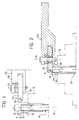
- a metal pipe indicated 10
- the tools required to close the end 12 comprise a tubular support 14 in which the pipe 10 is positioned.
- the support 14 is constituted, for example, by a resilient bush for insertion in a chuck 16 rotatable about an axis 18 coinciding with the longitudinal axis of the pipe 10.
- the support 14 has the main purpose of preventing damage to the external surface of the pipe 10 when it is gripped by the chuck 16.
- the support 14 has a flat surface 20 from which a portion A of the pipe 10 projects.
- the dimension A must be determined with care. In fact, if the dimension A is too small in comparison with the diameter D of the pipe 10 it is not possible to close the end whereas, if the dimension A is too large, excessive back-flow and deformation of the material are produced.
- A K + b D, in which :
- the rate of rotation of the pipe 10 about its axis during the operation to close the end 12 may vary from 600 to 1000 revolutions/minute.
- a normal value of the rate of rotation of the chuck 16 which achieves good results is about 800 revolutions/minute.
- the tools for closing the end of the pipe 10 also comprise a wheel 22 fixed idly to a tool-holder 24.
- the wheel 22 can rotate freely about an axis 26 parallel or substantially parallel to the axis 18 of the pipe 10.
- the tool-holder 24 can move along a straight line perpendicular to the axis 18 of the pipe 10 and indicated by the arrow 28 in Figure 1.
- the wheel 22 has a flat surface 30 which is substantially aligned with the flat surface 20 of the support 14.
- the distance between the surfaces 30 and 20 in a direction parallel to the axis 18 must be close to zero.
- the surface of the wheel 22 which is intended to contact the wall of the pipe 10 has a curvature 32 having a radius R which is equal to or greater than the dimension A by which the end to be closed projects.
- the idle wheel 22 represents the most appropriate tool for implementing the method according to the invention. However, a method could also be implemented with tools of different kinds not comprised in the invention. For example, a non-rotatable metal body having a profile similar to that of the cross-section of the wheel 22 could be used instead of the wheel 22.
- the idle wheel 22 has the advantage of reducing the contact friction and the heat which are generated during the deformation step of the pipe 10 and achieves a better result from the aesthetic point of view.
- the method according to the invention is implemented simply by the rotation of the pipe 10 and the movement of the tool-holder 24 towards the axis of 18 of the pipe 10 in the direction of the arrow 28.
- the forward movement of the tool-holder 24 is stopped when the junction between the arcuate surface 32 and the flat surface 30 is a little beyond the axis 18.
- Figure 2 shows the configuration of the tools and of the pipe 10 upon completion of the forward stroke of the tool-holder 24.
- the projecting portion of the pipe 10 has been completely flattened and turned over inwardly.
- the upsetting of the material and the heat of friction generated during the process bring about plastic deformation of the material which completely seals the end.
- the wheel 22 applies to the wall of the pipe 10 an inward deformation force the point of application of which varies continuously both circumferentially, as a result of the rotation of the pipe 10, and radially, as a result of the advance of the tool-holder 24.
- the effect of the inward deformation is to reduce the width of the hole progressively until it is completely closed.
- the closure produced requires no re-welding operations since it seals itself as a result of the heat of friction produced.
- the closure is particularly resistant to high working pressures.
- the method of the invention can easily be automated and, in comparison with a conventional welding method, is very easy to implement and has a minimal cost.
Landscapes
- Engineering & Computer Science (AREA)
- Mechanical Engineering (AREA)
- Physics & Mathematics (AREA)
- Thermal Sciences (AREA)
- General Engineering & Computer Science (AREA)
- Pressure Welding/Diffusion-Bonding (AREA)
- Forging (AREA)
- Heat Treatment Of Articles (AREA)
- Shaping Metal By Deep-Drawing, Or The Like (AREA)
- Pipe Accessories (AREA)
Applications Claiming Priority (2)
| Application Number | Priority Date | Filing Date | Title |
|---|---|---|---|
| ITTO950841 | 1995-10-18 | ||
| IT95TO000841A IT1280983B1 (it) | 1995-10-18 | 1995-10-18 | Procedimento per chiudere un'estremita' di un tubo metallico. |
Publications (2)
| Publication Number | Publication Date |
|---|---|
| EP0769337A1 EP0769337A1 (en) | 1997-04-23 |
| EP0769337B1 true EP0769337B1 (en) | 2002-04-17 |
Family
ID=11413896
Family Applications (1)
| Application Number | Title | Priority Date | Filing Date |
|---|---|---|---|
| EP96116206A Expired - Lifetime EP0769337B1 (en) | 1995-10-18 | 1996-10-10 | A method of closing an end of a metal pipe |
Country Status (5)
| Country | Link |
|---|---|
| EP (1) | EP0769337B1 (oth) |
| JP (1) | JP3819085B2 (oth) |
| DE (1) | DE69620703T2 (oth) |
| ES (1) | ES2171587T3 (oth) |
| IT (1) | IT1280983B1 (oth) |
Families Citing this family (15)
| Publication number | Priority date | Publication date | Assignee | Title |
|---|---|---|---|---|
| JP2002267390A (ja) * | 2001-03-09 | 2002-09-18 | Sanden Corp | 熱交換器 |
| ITMI20031239A1 (it) | 2003-06-19 | 2004-12-20 | S P I C E Group S R L | Metodo ed apparecchiatura per chiudere ermeticamente un tubo conducente gas o liquidi |
| FR2859654B1 (fr) * | 2003-09-11 | 2006-12-08 | Ems Societe | Procede d'obturation de l'extremite d'un tube metallique sans chauffage prealable et moyens destines a le mettre en oeuvre |
| ES2304269B1 (es) | 2005-08-03 | 2009-07-17 | Alberto Bellomo | Distribuidor de gas para una cocina, con un cierre del tubo. |
| CN102489617A (zh) * | 2011-12-02 | 2012-06-13 | 王平安 | 金属管封口工艺 |
| CN103480874B (zh) * | 2013-09-29 | 2015-10-28 | 浙江施克汽车配件有限公司 | 铝罐封口刀具 |
| CN103624175B (zh) * | 2013-11-28 | 2016-08-24 | 北京佛罗伦萨散热器有限公司 | 散热器支管封头机 |
| FR3034825B1 (fr) * | 2015-04-10 | 2017-03-31 | Clufix | Insert taraude |
| CN106975705A (zh) * | 2017-05-22 | 2017-07-25 | 礼泉鑫灞厨具有限公司 | 一种自动收口机 |
| CN108544189B (zh) * | 2018-04-16 | 2020-10-02 | 中国兵器工业第五九研究所 | 一种小尺寸中空薄壁壳体件的塑性成形方法 |
| CN115608864A (zh) * | 2021-07-16 | 2023-01-17 | 三花控股集团有限公司 | 管件加工部件及管件加工设备 |
| CN115608865A (zh) * | 2021-07-16 | 2023-01-17 | 三花控股集团有限公司 | 管件加工方法、管件加工部件及管件 |
| CN116251880A (zh) * | 2021-12-02 | 2023-06-13 | 三花控股集团有限公司 | 管件加工部件及管件加工设备 |
| CN117620608A (zh) * | 2023-12-05 | 2024-03-01 | 江苏欧朗汽车科技股份有限公司 | 一种新型不锈钢管成型封口设计及封口工艺 |
| CN119734092A (zh) * | 2025-03-05 | 2025-04-01 | 广州市万伟金属制品有限公司 | 紫铜管自动换位连续缩管装置 |
Family Cites Families (4)
| Publication number | Priority date | Publication date | Assignee | Title |
|---|---|---|---|---|
| US2408596A (en) * | 1944-03-13 | 1946-10-01 | Nat Tube Co | Method of forming cylinder ends |
| US3264729A (en) * | 1962-06-18 | 1966-08-09 | Gas Appliance Supply Corp | Method for closing the ends of pipes |
| DE3321363A1 (de) * | 1983-06-14 | 1984-12-20 | Th. Kieserling & Albrecht Gmbh & Co, 5650 Solingen | Drueckverfahren und schwenkform-drueckmaschine zur durchfuehrung des verfahrens |
| US5085131A (en) * | 1990-10-02 | 1992-02-04 | Prime Tube, Inc. | Hydraulic cylinder for automotive steering systems and the like |
-
1995
- 1995-10-18 IT IT95TO000841A patent/IT1280983B1/it active IP Right Grant
-
1996
- 1996-10-10 ES ES96116206T patent/ES2171587T3/es not_active Expired - Lifetime
- 1996-10-10 EP EP96116206A patent/EP0769337B1/en not_active Expired - Lifetime
- 1996-10-10 DE DE69620703T patent/DE69620703T2/de not_active Expired - Lifetime
- 1996-10-17 JP JP27472296A patent/JP3819085B2/ja not_active Expired - Fee Related
Also Published As
| Publication number | Publication date |
|---|---|
| IT1280983B1 (it) | 1998-02-11 |
| DE69620703D1 (de) | 2002-05-23 |
| ITTO950841A0 (oth) | 1995-10-18 |
| ES2171587T3 (es) | 2002-09-16 |
| DE69620703T2 (de) | 2002-10-17 |
| ITTO950841A1 (it) | 1997-04-18 |
| JPH09196278A (ja) | 1997-07-29 |
| JP3819085B2 (ja) | 2006-09-06 |
| EP0769337A1 (en) | 1997-04-23 |
Similar Documents
| Publication | Publication Date | Title |
|---|---|---|
| EP0769337B1 (en) | A method of closing an end of a metal pipe | |
| US5564177A (en) | Method of making captive O-ring face seal | |
| US3071993A (en) | Tube joints and means and method of making the same | |
| US4122701A (en) | Collar sleeves and process and tool for the manufacture thereof | |
| JPH05127B2 (oth) | ||
| US6154961A (en) | Method for manufacturing an water hammer arrester | |
| JP3167268B2 (ja) | 管の挿口の突部の形成方法 | |
| US3451243A (en) | Process for forming serrated flanged pipe | |
| US4558721A (en) | Double walled tubing | |
| CN1073896C (zh) | 柔性滚压双金属管及其生产方法 | |
| US20040222270A1 (en) | Method for manufacturing fuel inlet | |
| JPH09203456A (ja) | フランジ付パイプ及びフランジ付パイプの成形方法 | |
| JPH03142026A (ja) | パイプオンシート型熱交換器及びその製造方法 | |
| JP3997189B2 (ja) | チャック | |
| JP2851561B2 (ja) | 金属管の曲げ加工方法及びその装置 | |
| US20220234132A1 (en) | Systems and methods for internal channel formation within a workpiece | |
| US4987763A (en) | Tool in kit form for deforming metal | |
| US5354071A (en) | Welded wear sleeve for lubricant seals | |
| US4483061A (en) | Double walled tubing and process for producing same | |
| US5138863A (en) | Coupling for a gas pipe joint and associated method for making same and device therefor | |
| JPH0142768B2 (oth) | ||
| US3091025A (en) | Method of manufacturing expansion joints | |
| JPH049224A (ja) | 管継手部品の製造方法 | |
| US5033301A (en) | Coupling for a gas pipe joint and associated method for making same and device therefor | |
| US3435506A (en) | Method of forming a slot for a screwdriver |
Legal Events
| Date | Code | Title | Description |
|---|---|---|---|
| PUAI | Public reference made under article 153(3) epc to a published international application that has entered the european phase |
Free format text: ORIGINAL CODE: 0009012 |
|
| AK | Designated contracting states |
Kind code of ref document: A1 Designated state(s): DE ES FR GB SE |
|
| 17P | Request for examination filed |
Effective date: 19971014 |
|
| RAP1 | Party data changed (applicant data changed or rights of an application transferred) |
Owner name: MAGNETI MARELLI CLIMATIZZAZIONE S.P.A. |
|
| 17Q | First examination report despatched |
Effective date: 20000124 |
|
| GRAG | Despatch of communication of intention to grant |
Free format text: ORIGINAL CODE: EPIDOS AGRA |
|
| GRAG | Despatch of communication of intention to grant |
Free format text: ORIGINAL CODE: EPIDOS AGRA |
|
| GRAH | Despatch of communication of intention to grant a patent |
Free format text: ORIGINAL CODE: EPIDOS IGRA |
|
| REG | Reference to a national code |
Ref country code: GB Ref legal event code: IF02 |
|
| RAP1 | Party data changed (applicant data changed or rights of an application transferred) |
Owner name: DENSO THERMAL SYSTEMS S.P.A. |
|
| GRAH | Despatch of communication of intention to grant a patent |
Free format text: ORIGINAL CODE: EPIDOS IGRA |
|
| GRAA | (expected) grant |
Free format text: ORIGINAL CODE: 0009210 |
|
| AK | Designated contracting states |
Kind code of ref document: B1 Designated state(s): DE ES FR GB SE |
|
| REF | Corresponds to: |
Ref document number: 69620703 Country of ref document: DE Date of ref document: 20020523 |
|
| REG | Reference to a national code |
Ref country code: ES Ref legal event code: FG2A Ref document number: 2171587 Country of ref document: ES Kind code of ref document: T3 |
|
| ET | Fr: translation filed | ||
| PLBE | No opposition filed within time limit |
Free format text: ORIGINAL CODE: 0009261 |
|
| STAA | Information on the status of an ep patent application or granted ep patent |
Free format text: STATUS: NO OPPOSITION FILED WITHIN TIME LIMIT |
|
| 26N | No opposition filed |
Effective date: 20030120 |
|
| PGFP | Annual fee paid to national office [announced via postgrant information from national office to epo] |
Ref country code: SE Payment date: 20051005 Year of fee payment: 10 |
|
| PG25 | Lapsed in a contracting state [announced via postgrant information from national office to epo] |
Ref country code: SE Free format text: LAPSE BECAUSE OF NON-PAYMENT OF DUE FEES Effective date: 20061011 |
|
| EUG | Se: european patent has lapsed | ||
| PGFP | Annual fee paid to national office [announced via postgrant information from national office to epo] |
Ref country code: GB Payment date: 20101021 Year of fee payment: 15 |
|
| PGFP | Annual fee paid to national office [announced via postgrant information from national office to epo] |
Ref country code: ES Payment date: 20101020 Year of fee payment: 15 |
|
| GBPC | Gb: european patent ceased through non-payment of renewal fee |
Effective date: 20111010 |
|
| PG25 | Lapsed in a contracting state [announced via postgrant information from national office to epo] |
Ref country code: GB Free format text: LAPSE BECAUSE OF NON-PAYMENT OF DUE FEES Effective date: 20111010 |
|
| REG | Reference to a national code |
Ref country code: ES Ref legal event code: FD2A Effective date: 20130417 |
|
| PG25 | Lapsed in a contracting state [announced via postgrant information from national office to epo] |
Ref country code: ES Free format text: LAPSE BECAUSE OF NON-PAYMENT OF DUE FEES Effective date: 20111011 |
|
| PGFP | Annual fee paid to national office [announced via postgrant information from national office to epo] |
Ref country code: FR Payment date: 20131031 Year of fee payment: 18 |
|
| PGFP | Annual fee paid to national office [announced via postgrant information from national office to epo] |
Ref country code: DE Payment date: 20131230 Year of fee payment: 18 |
|
| REG | Reference to a national code |
Ref country code: DE Ref legal event code: R119 Ref document number: 69620703 Country of ref document: DE |
|
| PG25 | Lapsed in a contracting state [announced via postgrant information from national office to epo] |
Ref country code: DE Free format text: LAPSE BECAUSE OF NON-PAYMENT OF DUE FEES Effective date: 20150501 |
|
| REG | Reference to a national code |
Ref country code: FR Ref legal event code: ST Effective date: 20150630 |
|
| PG25 | Lapsed in a contracting state [announced via postgrant information from national office to epo] |
Ref country code: FR Free format text: LAPSE BECAUSE OF NON-PAYMENT OF DUE FEES Effective date: 20141031 |