EP0769327A2 - Device for powder coating - Google Patents
Device for powder coating Download PDFInfo
- Publication number
- EP0769327A2 EP0769327A2 EP96112635A EP96112635A EP0769327A2 EP 0769327 A2 EP0769327 A2 EP 0769327A2 EP 96112635 A EP96112635 A EP 96112635A EP 96112635 A EP96112635 A EP 96112635A EP 0769327 A2 EP0769327 A2 EP 0769327A2
- Authority
- EP
- European Patent Office
- Prior art keywords
- powder
- housing
- devices
- injector
- powder conveying
- Prior art date
- Legal status (The legal status is an assumption and is not a legal conclusion. Google has not performed a legal analysis and makes no representation as to the accuracy of the status listed.)
- Withdrawn
Links
Images

Classifications
-
- B—PERFORMING OPERATIONS; TRANSPORTING
- B05—SPRAYING OR ATOMISING IN GENERAL; APPLYING FLUENT MATERIALS TO SURFACES, IN GENERAL
- B05B—SPRAYING APPARATUS; ATOMISING APPARATUS; NOZZLES
- B05B7/00—Spraying apparatus for discharge of liquids or other fluent materials from two or more sources, e.g. of liquid and air, of powder and gas
- B05B7/14—Spraying apparatus for discharge of liquids or other fluent materials from two or more sources, e.g. of liquid and air, of powder and gas designed for spraying particulate materials
- B05B7/1404—Arrangements for supplying particulate material
- B05B7/1472—Powder extracted from a powder container in a direction substantially opposite to gravity by a suction device dipped into the powder
Definitions
- the invention relates to a device for powder coating according to the preamble of claim 1.
- Powder coating devices of this type are known from EP-B-0 184 994 and DE-A-38 27 014, 40 12 190 and 40 21 674.
- the containers from which the powder is sucked pneumatically and conveyed to a spraying device can be so-called containers in which the powder is delivered from the powder manufacturer to the powder user.
- the powder user sprays the powder onto objects to be coated and then melts the powder onto the coated object by heating.
- the object of the invention is to simplify the simultaneous use of a plurality of powder conveying devices in the same container and at the same time to reduce the time required for a color change.
- the device for powder coating can be immersed in a container together with all powder conveying devices either by their own weight or by hand or by a guide device or a lowering-lifting device in order to suck off powder therein.
- the powder conveyors can pneumatically convey the extracted powder to sprayers or to one or more other containers or to other locations.
- the powder coating device according to the invention shown in the drawings has a housing 4 and five powder conveying devices 2 accommodated therein. More, for example ten powder conveying devices 2 can also be accommodated in the housing 4.
- the powder conveying devices 2 are arranged in parallel next to one another and extend essentially over their entire length within the housing 4 in which they are fastened.
- the housing 4 consists of a housing wall 6 formed from a square tube, an upper connection plate 8, a lower connection plate 10 and screws 12 with which the connection plates 8 and 10 are detachably fastened to the housing wall 6.
- the two connection plates 8 and 10 are partially inserted into the end pipe ends of the housing wall 6, so that their outer peripheral surfaces are flush with one another.
- the flow paths of the powder conveying devices 2 extend through the two connection plates 8 and 10.
- Each powder conveying device 2 is of identical design and has a suction head 20 with an interchangeably inserted injector nozzle 22, an injector tube 24 acting as an injector catch nozzle, a powder tube 26 and a hose connection piece 28, which are arranged one after the other axially along a center line 30.
- the suction head 20 protrudes below from the lower connection plate 4, in which it is inserted removable.
- the injector nozzle 22 can be replaced when the suction head 20 is removed from the lower connection plate 4.
- a bore 32 serving as a powder suction inlet extends from the outside of the suction head into a chamber surrounding the injector nozzle 22, in which a compressed air conveying air flow flowing from the injector nozzle 22 into the injector tube 24 generates a vacuum and thereby sucks powder from the powder container 5 through the powder suction inlet 32 and then conveys the powder through the injector tube 24, the powder tube 26 and the hose connector 28 to a location, not shown, for example a spraying device or another container.
- the powder tube 26 is inserted at its ends into a through hole 34 of the upper connection plate 8 and into a through hole 36 of the lower connection plate 10 in a powder-tight manner.
- the injector tube 24 is inserted into the through bore 34 of the lower connection plate 10 and is located between the suction head 20 and the powder tube 26 attached to it.
- a compressed air tube 38 is inserted with its ends into through holes 40 and 42 of the two connection plates 8 and 4 in a compressed air-tight manner and via a connecting piece 44 screwed into the associated through bore 40 from the outside and a hose 46 can be connected to a compressed air source (not shown) in order to supply compressed air to the injector nozzle 22.
- one or more additional ones Compressed air tubes 48 can be inserted in bores 50 and 52 in a compressed air-tight manner in order to supply additional air into the injector tube 24 and / or the vacuum space, which adjoins the injector nozzle 22 and in which the conveying air flow of this injector nozzle 22 generates a vacuum.
- This additional air can be supplied from the same or a different compressed air source via a further connecting piece 54 and a further compressed air hose 58 through the bore 50 in the upper connecting plate 8 to the further compressed air pipe 48.
- Tubes may be used in place of tubes 26, 38, 48, and tubes may be used in place of tubes 46, 58.
- the injector which essentially consists of the injector nozzle 22 and the injector tube 24, is located at the lower and thus at the upstream end of the powder tube 26.
- the injector can be located on the Upper and thus at the downstream end of the powder tube 26, similar to what is known from DE-A 40 12 190 and 40 21 674 and EP-B-0 184 994.
- the powder tube 26 has the function of a riser tube or powder suction tube.
- the housing 4 encloses all parts of the powder conveying devices 2 in a powder-tight manner, with the exception of their powder suction inlet 32 at the lower end and with one exception of their connecting elements 28, 44 and 54 for connecting an external powder line and external compressed air lines.
- the powder conveying devices 2 can convey the powder to different spraying devices or to other locations, for example into another container or in parallel into different containers.
- the invention has the advantage that two or more, e.g. five or ten or twenty, powder conveyors 2 can be immersed together as one unit in a single powder container, either manually or automatically, and that the powder conveyors 2 are attached to most of them do not come into contact with powder on the outside.
- All parts of the powder conveying devices 2 are easily detachably connected to the connecting plates 8 and 10, preferably only by means of a plug connection, and to disassemble the entire device only one of the two connecting plates 8 or 10 needs to be separated from the housing wall 6 in order to disassemble the powder conveying devices or, conversely, to assemble.
Abstract
Description
Die Erfindung betrifft eine Vorrichtung zur Pulverbeschichtung gemäß dem Oberbegriff von Anspruch 1.The invention relates to a device for powder coating according to the preamble of claim 1.
Vorrichtungen zur Pulverbeschichtung dieser Art sind aus den EP-B-0 184 994 und den DE-A-38 27 014, 40 12 190 und 40 21 674 bekannt.Powder coating devices of this type are known from EP-B-0 184 994 and DE-A-38 27 014, 40 12 190 and 40 21 674.
Die Behälter, aus welchen das Pulver pneumatisch abgesaugt und zu einer Sprühvorrichtung gefördert wird, können sogenannte Gebinde sein, in welchen das Pulver vom Pulverhersteller zum Pulveranwender geliefert wird. Der Pulveranwender sprüht das Pulver auf Gegenstände, die zu beschichten sind, und schmilzt dann durch Erhitzung das Pulver auf den beschichteten Gegenstand.The containers from which the powder is sucked pneumatically and conveyed to a spraying device can be so-called containers in which the powder is delivered from the powder manufacturer to the powder user. The powder user sprays the powder onto objects to be coated and then melts the powder onto the coated object by heating.
Zur Zufuhr von Pulver aus einem einzigen Behälter zu mehreren Sprühvorrichtungen, sogenannten Sprühpistolen, ist es wünschenswert, mehrere Pulverfördervorrichtungen gleichzeitig in den Behälter einzutauchen.In order to supply powder from a single container to several spray devices, so-called spray guns, it is desirable to immerse several powder conveyors in the container at the same time.
Bei einem Wechsel der Pulversorte (Farbwechsel) müssen nicht nur die Pulverleitungen, sondern auch die Pulverfördervorrichtungen an ihren Außenseiten sehr gründlich gesäubert werden, damit das neue Pulver nicht durch Pulverpartikel des zuvor verwendeten Pulvers verunreinigt wird.When changing the powder type (color change), not only the powder lines, but also the powder conveying devices on the outside must be cleaned very thoroughly so that the new powder is not contaminated by powder particles of the previously used powder.
Durch die Erfindung soll die Aufgabe gelöst werden, die gleichzeitige Benutzung von mehreren Pulverfördervorrichtungen im gleichen Behälter zu vereinfachen und gleichzeitig die für einen Farbwechsel erforderliche Zeit zu reduzieren.The object of the invention is to simplify the simultaneous use of a plurality of powder conveying devices in the same container and at the same time to reduce the time required for a color change.
Diese Aufgabe wird gemäß der Erfindung durch die Merkmale von Anspruch 1 gelöst.This object is achieved according to the invention by the features of claim 1.
Weitere Merkmale der Erfindung sind in den Unteransprüchen enthalten.Further features of the invention are contained in the subclaims.
Die Vorrichtung zur Pulverbeschichtung kann gemäß der Erfindung mit allen Pulverfördervorrichtungen gemeinsam entweder durch ihr Eigengewicht oder von Hand oder durch eine Führungsvorrichtung oder eine Senk-Hub-Vorrichtung in einen Behälter eingetaucht werden, um darin Pulver abzusaugen. Die Pulverfördervorrichtungen können das abgesaugte Pulver zu Sprühvorrichtungen oder in einen oder in mehrere andere Behälter oder zu anderen Stellen pneumatisch fördern.According to the invention, the device for powder coating can be immersed in a container together with all powder conveying devices either by their own weight or by hand or by a guide device or a lowering-lifting device in order to suck off powder therein. The powder conveyors can pneumatically convey the extracted powder to sprayers or to one or more other containers or to other locations.
Die Erfindung wird im folgenden mit Bezug auf die Zeichnungen anhand einer bevorzugten Ausführungsform als Beispiel beschrieben. In den Zeichnungen zeigen schematisch
- Fig. 1
- einen horizontal abgebrochenen Vertikalschnitt durch eine Vorrichtung zur Pulverbeschichtung nach der Erfindung mit zwei nebeneinander angeordneten Pulverfördervorrichtungen,
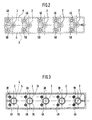
- Fig. 2
- eine Draufsicht auf eine abgewandelte Ausführungsform der Vorrichtung von Fig. 1, in der Ebene II - II von Fig. 1 gesehen, mit fünf hintereinander angeordneten Pulverfördervorrichtungen,
- Fig. 3
- eine Querschnittsansicht der Ausführungsform von Fig. 2 in der Ebene III - III von Fig. 1 gesehen.
- Fig. 1
- 3 shows a horizontally broken vertical section through a device for powder coating according to the invention with two powder conveying devices arranged next to one another,
- Fig. 2
- 1, seen in the plane II - II of FIG. 1, with five powder conveying devices arranged one behind the other,
- Fig. 3
- a cross-sectional view of the embodiment of FIG. 2 in the plane III - III of FIG. 1 seen.
Die in den Zeichnungen dargestellte Vorrichtung zur Pulverbeschichtung nach der Erfindung hat ein Gehäuse 4 und fünf darin untergebrachte Pulverfördervorrichtungen 2. In dem Gehäuse 4 können auch mehr, beispielsweise zehn Pulverfördervorrichtungen 2 untergebracht sein. Die Pulverfördervorrichtungen 2 sind parallel nebeneinander angeordnet und erstrecken sich im wesentlichen über ihre gesamte Länge innerhalb des Gehäuses 4, in welchem sie befestigt sind.The powder coating device according to the invention shown in the drawings has a housing 4 and five
Das Gehäuse 4 besteht aus einer aus einem Vierkantrohr gebildeten Gehäusewand 6, einer oberen Anschlußplatte 8, einer unteren Anschlußplatte 10 und Schrauben 12, mit welchen die Anschlußplatten 8 und 10 an der Gehäusewand 6 lösbar befestigt sind. Die beiden Anschlußplatten 8 und 10 sind in die stirnseitigen Rohrenden der Gehäusewand 6 teilweise eingesetzt, so daß ihre äußeren Umfangsflächen miteinander fluchten.The housing 4 consists of a
Die Strömungswege der Pulverfördervorrichtungen 2 erstrecken sich durch die beiden Anschlußplatten 8 und 10 hindurch.The flow paths of the
Jede Pulverfördervorrichtung 2 ist gleich ausgebildet und hat einen Ansaugkopf 20 mit einer darin auswechselbar eingesetzten Injektordüse 22, ein als Injektorfangdüse wirkendes Injektorrohr 24, ein Pulverrohr 26 und einen Schlauch-Anschlußstutzen 28, welche in dieser Reihenfolge nacheinander axial längs einer Mittellinie 30 angeordnet sind. Der Ansaugkopf 20 ragt unten aus der unteren Anschlußplatte 4 heraus, in welche er abziehbar eingesteckt ist. Die Injektordüse 22 kann ausgetauscht werden, wenn der Ansaugkopf 20 von der unteren Anschlußplatte 4 abgezogen wird. Durch den Ansaugkopf 20 erstreckt sich schräg zur Mittellinie 30 eine als Pulverabsaugeinlaß dienende Bohrung 32 von der Außenseite des Ansaugkopfes bis in eine die Injektordüse 22 umgebende Kammer, in welcher ein von der Injektordüse 22 in das Injektorrohr 24 strömender Druckluft-Förderluftstrom einen Unterdruck erzeugt und dadurch aus dem Pulverbehälter 5 durch den Pulverabsaugeinlaß 32 hindurch Pulver ansaugt und dann das Pulver durch das Injektorrohr 24, das Pulverrohr 26 und den Schlauch-Anschlußstutzen 28 zu einer nicht dargestellten Stelle, zum Beispiel einer Sprühvorrichtung oder einen anderen Behälter fördert. Das Pulverrohr 26 ist an seinen Enden in eine Durchgangsbohrung 34 der oberen Anschlußplatte 8 und in eine Durchgangsbohrung 36 der unteren Anschlußplatte 10 pulverdicht eingesteckt. Das Injektorrohr 24 ist in die Durchgangsbohrung 34 der unteren Anschlußplatte 10 eingesteckt und befindet sich zwischen dem auf ihn aufgesteckten Ansaugkopf 20 und dem Pulverrohr 26. Ein Druckluftrohr 38 ist mit seinen Enden in Durchgangsbohrungen 40 und 42 der beiden Anschlußplatten 8 und 4 druckluftdicht eingesteckt und über einen von außen in die zugehörige Durchgangsbohrung 40 eingeschraubten Anschlußstutzen 44 und einen Schlauch 46 mit einer nicht dargestellten Druckluftquelle verbindbar, um der Injektordüse 22 Druckluft zuzuführen. In gleicher Weise wie dieses Druckluftrohr 38 können ein oder mehrere zusätzliche Druckluftrohre 48 in Bohrungen 50 und 52 druckluftdicht eingesteckt sein, um Zusatzluft in das Injektorrohr 24 und/oder den Unterdruckraum zuzuführen, welcher an die Injektordüse 22 angrenzt und in welchem der Förderluftstrom dieser Injektordüse 22 einen Unterdruck erzeugt. Diese Zusatzluft kann von der gleichen oder einer anderen Druckluftquelle über einen weiteren Anschlußstutzen 54 und einen weiteren Druckluftschlauch 58 durch die Bohrung 50 in der oberen Anschlußplatte 8 dem weiteren Druckluftrohr 48 zugeführt werden.Each
Anstelle von Rohren 26, 38, 48 können Schläuche verwendet werden, und anstelle von Schläuchen 46, 58 können Rohre verwendet werden.Tubes may be used in place of
Bei der dargestellten Ausführungsform befindet sich der Injektor, welcher im wesentlichen aus der Injektordüse 22 und dem Injektorrohr 24 besteht, am unteren und damit am stromaufwärtigen Ende des Pulverrohres 26. Gemäß anderen Ausführungsformen, die nicht in den Zeichnungen dargestellt sind, kann sich der Injektor am oberen und damit am stromabwärtigen Ende des Pulverrohres 26 befinden, ähnlich wie dies aus den DE-A 40 12 190 und 40 21 674 sowie EP-B-0 184 994 bekannt ist. Bei dieser abgewandelten Form hat das Pulverrohr 26 die Aufgabe eines Steigrohres oder Pulveransaugrohres.In the embodiment shown, the injector, which essentially consists of the
Das Gehäuse 4 umschließt pulverdicht alle Teile der Pulverfördervorrichtungen 2, mit Ausnahme von deren Pulverabsaugeinlaß 32 am unteren Ende und mit Ausnahme von deren Anschlußelementen 28, 44 und 54 zum Anschluß einer externen Pulverleitung und externen Druckluftleitungen.The housing 4 encloses all parts of the
Die Pulverfördervorrichtungen 2 können das Pulver zu verschiedenen Sprühvorrichtungen oder zu anderen Stellen fördern, zum Beispiel in einen weiteren Behälter oder parallel in verschiedene Behälter.The
Bei allen Ausführungsformen ergibt die Erfindung den Vorteil, daß zwei oder mehr, beispielsweise fünf oder zehn oder zwanzig, Pulverfördervorrichtungen 2 zusammen als eine Baueinheit in einen einzigen Pulverbehälter eingetaucht werden können, entweder von Hand oder automatisch, und daß die Pulverfördervorrichtungen 2 an den meisten von ihren Außenseiten nicht mit Pulver in Berührung kommen. Bei einem Pulverwechsel brauchen lediglich die Außenflächen des Gehäuses 4 gereinigt zu werden, jedoch nicht die Außenflächen der einzelnen Pulverfördervorrichtungen. Alle Teile der Pulverfördervorrichtungen 2 sind mit den Anschlußplatten 8 und 10 leicht lösbar verbunden, vorzugsweise nur durch eine Steckverbindung, und zum Zerlegen der gesamten Vorrichtung braucht lediglich eine der beiden Anschlußplatten 8 oder 10 von der Gehäusewand 6 getrennt zu werden, um die Pulverfördervorrichtungen zu demontieren oder, umgekehrt, zu montieren. Zum Auswechseln oder Reinigen einer Injektordüse 22 braucht lediglich der Ansaugkopf 20 von der unteren Anschlußplatte 10 abgezogen zu werden.In all embodiments, the invention has the advantage that two or more, e.g. five or ten or twenty,
Claims (7)
dadurch gekennzeichnet, daß alle Pulverfördervorrichtungen (2), die zur Pulverförderung aus dem gleichen Behälter vorgesehen sind, in einem Gehäuse (4) untergebracht und befestigt sind, welches alle diese Pulverfördervorrichtungen (2) mindestens um ihre Teile, welche in den Pulverbehälter eintauchbar sind, pulverdicht umschließt, mit Ausnahme eines Pulverabsaugeinlasses (32) der Pulverfördervorrichtungen (2), in welchen die Pulverfördervorrichtungen Pulver aus dem Behälter einsaugen, und daß das Gehäuse (4) und alle in ihm befestigten Pulverfördervorrichtungen (2) zusammen eine Baueinheit bilden, welche mit allen Pulverfördervorrichtungen (2) zusammen und gleichzeitig in den gleichen Behälter eintauchbar ist.Device for powder coating with the following features: two or more powder conveying devices (2), each having at least one injector (22, 24), a compressed air channel (38) for supplying compressed air to the injector and a powder line (40) for conveying the injector have sucked powder, the powder conveying devices being immersed in a powder container in order to suck powder from it,
characterized in that all powder conveying devices (2) which are provided for powder conveying from the same container are accommodated and fastened in a housing (4) which contains all these powder conveying devices (2) at least around their parts which can be immersed in the powder container, encloses in a powder-tight manner, with the exception of a powder suction inlet (32) of the powder conveying devices (2), in which the powder conveying devices suck in powder from the container, and that the housing (4) and all powder conveying devices (2) fastened in it form a structural unit which together with all Powder conveyors (2) together and at the same time immersed in the same container.
dadurch gekennzeichnet, daß die Pulverfördervorrichtungen (2) eine stabartig längliche Form haben, an deren unterem Ende der Pulverabsaugeinlaß (32) gebildet ist, daß das Gehäuse (4) eine obere Anschlußplatte (8) am oberen Ende der Pulverabsaugvorrichtungen (2) und eine untere Anschlußplatte (10) am unteren Ende der Pulverabsaugvorrichtungen (2) sowie eine die beiden Platten (8, 10) miteinander verbindende Gehäusewand (6) aufweist, und daß sich durch die beiden Platten (8, 10) die Strömungswege (26, 38, 48, 34, 36, 40, 42, 50, 52) der Pulverfördervorrichtungen (2) hindurch erstrecken.Device according to claim 1,
characterized in that the powder conveying devices (2) have a rod-like elongated shape, at the lower end of which the powder suction inlet (32) is formed, in that the housing (4) has an upper connecting plate (8) at the upper end of the powder suction devices (2) and a lower one Connection plate (10) at the lower end of the powder suction devices (2) and one connecting the two plates (8, 10) Has housing wall (6), and that the flow paths (26, 38, 48, 34, 36, 40, 42, 50, 52) of the powder conveying devices (2) extend through the two plates (8, 10).
dadurch gekennzeichnet, daß die Gehäusewand (6) an den beiden Platten (8, 10) lösbar befestigt ist.Device according to claim 2,
characterized in that the housing wall (6) is releasably attached to the two plates (8, 10).
dadurch gekennzeichnet, daß die Gehäusewand (6) ein Vierkantrohr ist, dessen Enden durch die beiden Platten (8, 10) verschlossen sind.Device according to claim 2 or 3,
characterized in that the housing wall (6) is a square tube, the ends of which are closed by the two plates (8, 10).
dadurch gekennzeichnet, daß der Injektor (22, 24) am unteren Ende seiner Pulverfördervorrichtung (2) angeordnet ist.Device according to one of claims 1 to 4,
characterized in that the injector (22, 24) is arranged at the lower end of its powder conveying device (2).
dadurch gekennzeichnet, daß der Injektor (22, 24) oder mindestens ein Teil (20) von jedem Injektor (22, 24) von der Gehäuseaußenseite her lösbar mit seiner Pulverfördervorrichtung (2) verbunden ist, derart, daß der Injektor (22, 24) ganz von seiner Pulverfördervorrichtung (2) abnehmbar ist oder geöffnet werden kann, je ohne daß das Gehäuse (6) geöffnet oder die betreffende Pulverfördervorrichtung (2) aus dem Gehäuse (6) herausgenommen zu werden braucht.Device according to claim 5,
characterized in that the injector (22, 24) or at least a part (20) of each injector (22, 24) is detachably connected to its powder conveying device (2) from the outside of the housing, such that the injector (22, 24) is completely removable from its powder conveying device (2) or can be opened, without the housing (6) being opened or the one in question Powder conveying device (2) needs to be removed from the housing (6).
dadurch gekennzeichnet, daß die Pulverfördervorrichtungen (2) parallel nebeneinander angeordnet sind.Device according to one of the preceding claims,
characterized in that the powder conveying devices (2) are arranged parallel next to one another.
Applications Claiming Priority (2)
| Application Number | Priority Date | Filing Date | Title |
|---|---|---|---|
| DE19538926A DE19538926A1 (en) | 1995-10-19 | 1995-10-19 | Powder coating device |
| DE19538926 | 1995-10-19 |
Publications (2)
| Publication Number | Publication Date |
|---|---|
| EP0769327A2 true EP0769327A2 (en) | 1997-04-23 |
| EP0769327A3 EP0769327A3 (en) | 1998-01-14 |
Family
ID=7775256
Family Applications (1)
| Application Number | Title | Priority Date | Filing Date |
|---|---|---|---|
| EP96112635A Withdrawn EP0769327A3 (en) | 1995-10-19 | 1996-08-05 | Device for powder coating |
Country Status (5)
| Country | Link |
|---|---|
| US (1) | US5765971A (en) |
| EP (1) | EP0769327A3 (en) |
| JP (1) | JPH09164362A (en) |
| DE (1) | DE19538926A1 (en) |
| TR (1) | TR199600821A2 (en) |
Cited By (2)
| Publication number | Priority date | Publication date | Assignee | Title |
|---|---|---|---|---|
| US6194027B1 (en) | 1997-11-03 | 2001-02-27 | Itw Gema Ag | Method and equipment for powder spray coating |
| US6217654B1 (en) | 1997-11-03 | 2001-04-17 | Itw Gema Ag | Method and equipment for powder spray coating |
Families Citing this family (10)
| Publication number | Priority date | Publication date | Assignee | Title |
|---|---|---|---|---|
| US6852164B2 (en) | 1998-05-22 | 2005-02-08 | Nordson Corporation | Powder supply system for coating installations with a plurality of application units |
| DE19823068A1 (en) * | 1998-05-22 | 1999-11-25 | Erich Kraemer | Powder supply system for powder coating appliance |
| US6705545B1 (en) | 1998-11-13 | 2004-03-16 | Steelcase Development Corporation | Quick color change powder paint system |
| DE19903578A1 (en) * | 1999-01-29 | 2000-08-03 | Erich Kraemer | Central powder supply system |
| US6478242B1 (en) | 1999-09-16 | 2002-11-12 | Nordson Corporation | Powder spray gun |
| US20030080220A1 (en) * | 1999-09-16 | 2003-05-01 | Mather Brian D. | Powder spray gun with inline angle spray nozzle |
| WO2003031075A1 (en) * | 1999-09-16 | 2003-04-17 | Nordson Corporation | Powder spray gun with inline angle spray nozzle |
| DE102010039473B4 (en) * | 2010-08-18 | 2014-11-20 | Gema Switzerland Gmbh | Powder supply device for a powder coating system |
| GB2566452A (en) | 2017-09-12 | 2019-03-20 | Carlisle Fluid Tech Inc | Colour change system for powder coating |
| WO2024044626A1 (en) * | 2022-08-25 | 2024-02-29 | Boston Scientific Scimed, Inc. | Weighted manifold for an endoscope |
Citations (5)
| Publication number | Priority date | Publication date | Assignee | Title |
|---|---|---|---|---|
| DE2102678A1 (en) * | 1971-01-21 | 1972-08-24 | Robert Bosch Gmbh, 7000 Stuttgart | Facility with a fluidized bed |
| FR2215375A1 (en) * | 1973-01-25 | 1974-08-23 | Carrier | |
| EP0059781A2 (en) * | 1981-03-07 | 1982-09-15 | GABLER GmbH & Co., KG. | Arrangement for the pneumatic or hydraulic lifting and conveying of material to be conveyed |
| EP0184994B1 (en) * | 1984-09-26 | 1988-05-18 | Siegfried Frei | Powder exhauster |
| EP0453750A2 (en) * | 1990-04-24 | 1991-10-30 | Metri Airfluid Ag | Device for fluidising power contained in a container and evacuating fluidised powder directly towards a spray gun of an electrostatic powder coating device |
Family Cites Families (7)
| Publication number | Priority date | Publication date | Assignee | Title |
|---|---|---|---|---|
| DE1005413B (en) * | 1955-02-28 | 1957-03-28 | Knapsack Ag | Method and device for applying protective coatings made of fusible pulverulent substances to objects of any kind by spraying the powder with a flame spraying device |
| US3826540A (en) * | 1973-03-21 | 1974-07-30 | Elektro Ion | Powder hopper for electrostatic powder spraying apparatus |
| CA998410A (en) * | 1974-01-16 | 1976-10-12 | Charles R. Vertue | Particulate material conveying apparatus |
| EP0450295A3 (en) * | 1990-04-04 | 1992-01-08 | Wagner International Ag | Fluidising and conveying device |
| DE4021674A1 (en) * | 1990-07-07 | 1992-01-16 | Gema Ransburg Ag | Pneumatic powder conveyor with pipe arrangement - consists of suction and compressed air pipes with spacer pieces at top and bottom |
| DE9105321U1 (en) * | 1991-04-30 | 1991-06-20 | Gebrueder Thiemt Ohg, 4520 Melle, De | |
| DE4415828A1 (en) * | 1994-05-05 | 1995-06-29 | Gema Volstatic Ag | Tilting table for powder container |
-
1995
- 1995-10-19 DE DE19538926A patent/DE19538926A1/en not_active Ceased
-
1996
- 1996-08-05 EP EP96112635A patent/EP0769327A3/en not_active Withdrawn
- 1996-09-24 US US08/718,879 patent/US5765971A/en not_active Expired - Fee Related
- 1996-10-17 JP JP8274427A patent/JPH09164362A/en not_active Abandoned
- 1996-10-17 TR TR96/00821A patent/TR199600821A2/en unknown
Patent Citations (5)
| Publication number | Priority date | Publication date | Assignee | Title |
|---|---|---|---|---|
| DE2102678A1 (en) * | 1971-01-21 | 1972-08-24 | Robert Bosch Gmbh, 7000 Stuttgart | Facility with a fluidized bed |
| FR2215375A1 (en) * | 1973-01-25 | 1974-08-23 | Carrier | |
| EP0059781A2 (en) * | 1981-03-07 | 1982-09-15 | GABLER GmbH & Co., KG. | Arrangement for the pneumatic or hydraulic lifting and conveying of material to be conveyed |
| EP0184994B1 (en) * | 1984-09-26 | 1988-05-18 | Siegfried Frei | Powder exhauster |
| EP0453750A2 (en) * | 1990-04-24 | 1991-10-30 | Metri Airfluid Ag | Device for fluidising power contained in a container and evacuating fluidised powder directly towards a spray gun of an electrostatic powder coating device |
Cited By (2)
| Publication number | Priority date | Publication date | Assignee | Title |
|---|---|---|---|---|
| US6194027B1 (en) | 1997-11-03 | 2001-02-27 | Itw Gema Ag | Method and equipment for powder spray coating |
| US6217654B1 (en) | 1997-11-03 | 2001-04-17 | Itw Gema Ag | Method and equipment for powder spray coating |
Also Published As
| Publication number | Publication date |
|---|---|
| DE19538926A1 (en) | 1997-04-24 |
| US5765971A (en) | 1998-06-16 |
| TR199600821A2 (en) | 1997-05-21 |
| EP0769327A3 (en) | 1998-01-14 |
| JPH09164362A (en) | 1997-06-24 |
Similar Documents
| Publication | Publication Date | Title |
|---|---|---|
| EP0577681B1 (en) | Slit nozzle for delivering liquids | |
| EP0108929B2 (en) | Apparatus for dispensing a liquid | |
| EP0599087B1 (en) | Device for lubricating and cleaning of chains and rails | |
| DE19728155A1 (en) | Cleaning and preparation method for paint spray pipe | |
| EP0540774A1 (en) | Fluid atomizing device | |
| DE102004033604A1 (en) | Powder color changer | |
| EP0769327A2 (en) | Device for powder coating | |
| EP0290869B1 (en) | Device for interchangeable connections | |
| DE3927880C2 (en) | Process and plant for coating objects with frequently changing color material | |
| EP0913203B1 (en) | Method and apparatus for powder coating with purging air supply | |
| EP0760259B1 (en) | Injector device for powder spray coating | |
| EP0718047A2 (en) | Injection device for conveying coating powder | |
| EP0888825A2 (en) | Method and device for painting | |
| EP0689875A2 (en) | Pneumatic apparatus for conveying powder, particularly coating powder | |
| DE3209726A1 (en) | DEVICE FOR DEVELOPING OFFSET PRINTING PLATES | |
| EP0718043A1 (en) | Powder coating installation | |
| DE4114097A1 (en) | Jet pump for spraying powder - has entrainment nozzles which are arranged to reduce wear and to be easily cleaned | |
| DE69916466T2 (en) | LUBRICANT DISPENSER | |
| DE4223006A1 (en) | Device for treating workpieces with a pressure fluid | |
| DE4417727A1 (en) | Hose brush for pipelines in powder spray-coating plants | |
| DE19914040B4 (en) | Spray gun robot adapter | |
| DE4027421A1 (en) | Manual liq. spray appliance - incorporates pressurised material tank with tube inside | |
| EP0541745A1 (en) | Spray coating device. | |
| DE4312994C2 (en) | Device for spraying suspensions, in particular mortars | |
| DE19817377A1 (en) | Cleaning and preparation method for paint spray pipe |
Legal Events
| Date | Code | Title | Description |
|---|---|---|---|
| PUAI | Public reference made under article 153(3) epc to a published international application that has entered the european phase |
Free format text: ORIGINAL CODE: 0009012 |
|
| 17P | Request for examination filed |
Effective date: 19960805 |
|
| AK | Designated contracting states |
Kind code of ref document: A2 Designated state(s): AT BE CH DE FR GB IT LI NL |
|
| PUAL | Search report despatched |
Free format text: ORIGINAL CODE: 0009013 |
|
| AK | Designated contracting states |
Kind code of ref document: A3 Designated state(s): AT BE CH DE FR GB IT LI NL |
|
| STAA | Information on the status of an ep patent application or granted ep patent |
Free format text: STATUS: THE APPLICATION IS DEEMED TO BE WITHDRAWN |
|
| 18D | Application deemed to be withdrawn |
Effective date: 19980715 |