EP0768624A2 - Recul pendant le régénération dans un système C.A.O. (Conception Assistée pour Ordinateur) - Google Patents
Recul pendant le régénération dans un système C.A.O. (Conception Assistée pour Ordinateur) Download PDFInfo
- Publication number
- EP0768624A2 EP0768624A2 EP96401889A EP96401889A EP0768624A2 EP 0768624 A2 EP0768624 A2 EP 0768624A2 EP 96401889 A EP96401889 A EP 96401889A EP 96401889 A EP96401889 A EP 96401889A EP 0768624 A2 EP0768624 A2 EP 0768624A2
- Authority
- EP
- European Patent Office
- Prior art keywords
- model
- entities
- version
- storing
- input command
- Prior art date
- Legal status (The legal status is an assumption and is not a legal conclusion. Google has not performed a legal analysis and makes no representation as to the accuracy of the status listed.)
- Withdrawn
Links
- 238000011960 computer-aided design Methods 0.000 title claims description 57
- 238000011069 regeneration method Methods 0.000 title description 14
- 230000008929 regeneration Effects 0.000 title description 13
- 238000000034 method Methods 0.000 claims description 44
- 230000004044 response Effects 0.000 claims description 15
- 230000004048 modification Effects 0.000 claims description 14
- 238000012986 modification Methods 0.000 claims description 14
- 230000009849 deactivation Effects 0.000 description 13
- 230000004913 activation Effects 0.000 description 11
- 239000007787 solid Substances 0.000 description 10
- 230000008859 change Effects 0.000 description 7
- 238000013461 design Methods 0.000 description 3
- 238000010586 diagram Methods 0.000 description 2
- 238000012545 processing Methods 0.000 description 2
- 230000001172 regenerating effect Effects 0.000 description 2
- 230000003252 repetitive effect Effects 0.000 description 2
- 208000020180 CADDS Diseases 0.000 description 1
- 230000005540 biological transmission Effects 0.000 description 1
- 230000015572 biosynthetic process Effects 0.000 description 1
- 230000000694 effects Effects 0.000 description 1
- 230000006870 function Effects 0.000 description 1
- 230000008569 process Effects 0.000 description 1
- 230000000135 prohibitive effect Effects 0.000 description 1
- 238000012360 testing method Methods 0.000 description 1
- 230000000007 visual effect Effects 0.000 description 1
Images


Classifications
-
- G—PHYSICS
- G06—COMPUTING; CALCULATING OR COUNTING
- G06T—IMAGE DATA PROCESSING OR GENERATION, IN GENERAL
- G06T17/00—Three dimensional [3D] modelling, e.g. data description of 3D objects
Definitions
- This invention relates to creating entities and regenerating models in a computer-aided design (CAD) system.
- CAD computer-aided design
- a computer-aided design (CAD) system is a tool that allows a user to create models on a computer system.
- the user builds a model with a series of commands that perform tasks that instruct the CAD system to produce model entities such as solids, curves, or lines; form contours; and define dimensions.
- Typical models are made through the execution of hundreds or even thousands of such commands.
- a geometric modeler receives the commands and generates entities based on a set of rules defined in application code. These entities, such as solids and portions of solids including faces and edges, are created as data stored in a database.
- the entities include tags that have a number of fields, including an entity number, data that interrelates the entity to other entities, and other useful information.
- the geometric modeler typically creates a new set of entities and stores them in the database.
- CAD systems currently in use such as the CADDS line available from Computervision Corp. in Bedford, Massachusetts, typically delete some or all of the previous entities and replace the deleted entities with new entities. This replacement is done because storing data for all the new and old entities for each command would quickly use up prohibitively large amounts of storage.
- a designer may decide to alter one or more of the previous commands. For example, a designer may want to make a radius of a particular cylinder larger or smaller, or to change an angle of a chamfer.
- Early CAD systems captured keystrokes entered by the user, and allowed the user to edit and re-run an earlier sequence of commands. Such a system required the user, often a design engineer, to locate the dimension or property to be changed in the command list, and to function as a programmer in editing the sequence.
- a system of parameterization and regeneration has also been developed.
- a user can designate, typically with a mouse, a portion of a model to be altered. The user can then enter a modification to alter or eliminate an entity in the model, or to undo a command.
- a designer could point to a circular opening in a cube, and change the radius to enlarge the opening.
- Conventional parametrerization systems regenerate at least some of the commands that were entered prior to the command that the designer wants to modify. If, for example, a designer entered commands numbered one through fifty and then wanted to change the radius of a cylinder created in command number thirty-five, some or all of the thirty-four commands leading up to command number fifty would be regenerated, which can take up a substantial amount of time.
- a user is allowed to choose between the original model and the regenerated model.
- the other is typically discarded to prevent excessive storage of data.
- a method for updating a first version of a model in a CAD system in response to a request to regenerate the model with a modification to generate a second version of the model.
- the CAD system includes a computer and a database, and creates model entities in response to input commands.
- the first version of the model includes a plurality of model entities created during the execution of a sequence of input commands.
- the request to regenerate the model identifies at least one modified input command, corresponding to an input command in the sequence that is modified to define the modification to the first version of the model.
- the method includes the computer implemented steps of (a) storing in the database the plurality of model entities of the first version of the model created by the input commands in the sequence; (b) storing identification information for each model entity that identifies at what stage in the sequence of commands the entity was included in the first version of the model; (c) when the request to regenerate the model is received, identifying model entities that were included in the first version of the model following execution of an input command in the sequence that immediately precedes the input command corresponding to the modified input command; (d) retrieving the identified model entities from the database to be included in the second version of the model; and (e) executing the modified input command and each input command that follows it in the sequence to create additional model entities that complete the second version of the model.
- a method for storing multiple versions of a model in a CAD system, the CAD system storing at least first and second versions of the model, the at least first and second versions of the model each including a plurality of model entities, the CAD system including a computer having a database.
- the method includes the computer implemented steps of: (a) storing in the database each of the plurality of model entities included in the first version of the model; (b) identifying a first group of model entities included in the second version of the model that are also included in the first version of the model, and a second group of model entities in the second version of the model that are not included in the first version of the model; (c) storing in the database each of the plurality of model entities included in the second group; and (d) storing in the database information identifying each of the stored model entities included in the first version of the model as belonging to the first version, identifying each of the model entities in the first group as also belonging to the second version of the model, and identifying each of the model entities in the second group as belonging to the second version of the model.
- a method for updating an original version of a model in a CAD system in response to a request to regenerate the model with a modification to generate a regenerated version of the model.
- the CAD system creates model entities in response to input commands.
- the original version of the model includes a plurality of model entities created during the execution of a plurality of input commands received in a sequence, the request to regenerate the model identifying at least one modified input command, the at least one modified input command corresponding to an input command in the sequence that is modified to define the modification to the model.
- the original version of the model has a plurality of states corresponding to the plurality of input commands received in the sequence, such that the original version of the model has a unique state following the execution of each of the plurality of input commands, each state of the model including at least one model entity.
- the illustrative method including the computer implemented steps of: (a) storing in the database the plurality of model entities of the original version of the model created by the plurality of input commands in the sequence; (b) storing information identifying each of the plurality of states of the model; (c) when the request to regenerate the model is received, identifying the at least one model entity that was included in the state of the original version of the model following execution of an input command in the sequence that immediately precedes the input command corresponding to the modified input command; (d) retrieving the at least one model entity identified in step (c) from the database to be included in the regenerated version of the model; and (e) executing the modified input command and each input command that follows it in the sequence to create additional model entities that complete the regenerated version of the model.
- a CAD system that generates model entities in response to received input commands, the CAD system responding to a sequence of input commands to generate an original version of a model that includes a plurality of model entities, the CAD system also responding to a regenerate command to generate a regenerated version of the model.
- the regenerated version of the model includes a plurality of model entities.
- the regenerate command identifies at least one modified input command that corresponds to an input command in the sequence that is modified to define a modification to the original version of the model.
- the CAD system includes a database; means for storing in the database the plurality of model entities of the original version generated in response to receipt of each input command in the sequence; means for storing identification information in the database for each of the plurality of model entities of the original version that identifies at what stage in the sequence of commands the model entity was included in the original version of the model; identification means, responsive to receipt of the regenerate command, for identifying model entities that were included in the original version of the model following execution of an input command in the sequence that immediately precedes the input command corresponding to the modified input command; means, responsive to the identification means, for retrieving the identified model entities from database; means for executing the modified input command and each input command that follows it in the sequence to create regenerated model entities; and means for combining the retrieved model entities and the regenerated model entities to generate the regenerated version of the model.
- a CAD system that generates model entities in response to received input commands, the CAD system responding to input commands to generate an original version of a model that includes a plurality of model entities, the CAD system also responding to a regenerate command to generate a regenerated version of the model that also includes a plurality of model entities.
- the CAD system includes a database; means for storing in the database each of the plurality of model entities included in the first version of the model; means for identifying a first group of model entities included in the regenerated version of the model that are also included in the original version of the model, and a second group of model entities in the regenerated version of the model that are not included in the original version of the model; means for storing in the memory each of the plurality of model entities included in the second group; and means for storing in the memory information identifying each of the model entities included in the original version of the model as corresponding to the original version, identifying each of the model entities in the first group as also corresponding to the regenerated version of the model, and identifying each of the model entities in the second group as corresponding to the regenerated version of the model.
- a CAD system when new commands are entered, newly created entities are added to the database while old entities, rather than being deleted, are kept but identified as suspended or deactivated.
- Each entity is preferably provided with an activation field indicating when the entity was activated, and a deactivation field indicating if or when the entity was deactivated. From this information, the system can determine the state of the model at the time of any given command. Consequently, all commands leading up to a command that is to be altered do not have to be regenerated, but rather, only those commands which occurred after the altered command.
- information is maintained that indicates when each entity in a model is activated or deactivated.
- the present invention keeps entities that are unchanged, stores deactivated entities with a deactivation field indicating when they were deactivated, and creates new entities in response to the new command. In this way, the state of the model can easily and quickly be determined after any given command.
- multiple versions of a model including regenerated versions, are maintained.
- the entities have one or more version fields that reference different versions of a model so that one entity may refer to several different versions. After several versions of a model have been created, a user can select which of the versions to keep. This feature also allows for greater storage of models without prohibitive storage requirements.
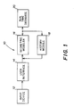
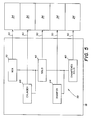
- a CAD system 10 has a user interface 14 that receives user-entered commands from an input device 12, such as a mouse, keyboard, track ball, touch sensitive screen, track pad, or any other input device that allows a user to enter information.
- the user-entered commands are provided from interface 14 to a geometric modeler 16.
- Modeler 16 receives the commands and calls routines in application code (not shown) that generates model entities, such as faces and edges, based on the user-entered commands.
- Information about each entity is stored as a "tag" for the entity.
- a current state of a model created on the system is maintained in a run-time database 20, which holds all entities that have been not deactivated or otherwise superseded by later commands.
- a list of received commands and a hierarchical tree structure of the resulting model are maintained in a history module 18. If a user makes changes to the model so that regeneration is necessary, commands that are to be regenerated are provided to modeler 16 from the list of commands kept in history module 18. History module 18 thus serves as a source of inputs during model regeneration.
- Modeler 16, history module 18, and database 20 are implemented by a combination of processing hardware and software.
- the processing hardware may be a workstation, such as a Sun Microsystems Sparc 10.
- the hardware system should include a user interface (e.g., a keyboard and a mouse), one or more processors, a visual display, and either large scale storage or access to such storage (e.g., over a network of computers).
- the system may be used with the X-windows operating system, also available from Sun Microsystems.
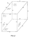
- a simple example of a model is provided for illustrative purposes.
- a user enters a command to create a box 30 (command one).
- the geometric modeler 16 (Fig. 1) receives the command in a simplified command language and calls a routine in application code that creates twelve edges, six faces, and eight vertices.
- edges are represented as eI (wherein I is an integer from 1-12), and faces are represented as fM (where M is an integer from 1-6), while vertices are not separately identified for convenience.
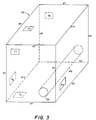
- a user next creates a cylinder 48 by executing command two, and removes the cylinder from box 30 by executing command three.
- the CAD system may have different command terminology to accomplish this task, e.g., commands two and three might be replaced with a command such as "make hole” or "drill hole”.
- the execution of command three results in the modification of faces f1 and f3, which are deactivated and replaced with new faces f7 and f8 on box 30.
- the execution of command three results in the creation of new faces and edges (not separately identified for convenience) for representing bore 32.
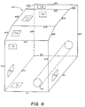
- Fig. 4 illustrates another change made to the model by the execution of a command four, which is a chamfer command that causes edges e3 and e7 to be chamfered, thus modifying face f7 to create new faces f9 and f14, modifying face f8 to create new faces f12 and f15, modifying face f5 to create new face f11, and modifying faces f4 and f6 to respectively create new faces f13 and f10.
- all of the faces in solid 42 of Fig. 3 are altered by command four, with the exception of face f2.
- Edges e1, e5, e9, and e12 are unchanged, while new edges e13-e26 are created.
- Fig. 5 represents a history module 18 that would be created by the above-described execution of commands one through four.
- the history module stores a hierarchical tree structure 38 that relates the model entities.
- Chamfered solid 40 represents the structure of Fig. 4, created by command four.
- Chamfered solid 40 depends on solid 42, and a chamfer 44.
- Solid 42 represents the structure of Fig. 3, created by commands one through three, and results from a box 30 created by command one, and a cylinder 48 removed from the box in command three.
- Each of the entries in tree 38 has a pointer 50 that points to a location 54 in database 22, where the faces, edges, and vertices that form the model are stored.
- the history module also contains the commands (not shown) that were entered by the user to create each of the model entities.
- a designer may decide to further modify the design, for example, by increasing the radius and thereby enlarging the bore 32.
- the bore was formed by creating cylinder 48 and subtracting it from box 30, the box and the cylinder would be regenerated to implement the design modification. Consequently, such a system would regenerate command one to recreate the box.
- the state of the model after execution of each command is maintained through the tag information stored in the database.
- the chamfer can be redone or undone by regenerating only the chamfer command.
- tags that correspond to the model entities are created and stored, each includes an activation field that indicates when its corresponding entity was created, and a deactivation field that indicates if or when the entity was deactivated.
- each of the entities i.e., the faces, edges and vertices
- faces fl and f4 are replaced with faces f7 and f8. Therefore, replaced faces fl and f4 have information in their respective fields indicating deactivation at command three, but those entities are saved for potential future use.
- Faces f7 and f8 have information in their respective activation fields indicating that they were created by command three. Since the other faces and edges are unaffected by subtracting the cylinder from the box, they are left unchanged. Furthermore, all original edges remain unchanged, while new edges (not separately identified) are created around bore 32.
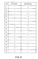
- the tags for faces f1-f15 are stored in a table that indicates when all the faces were activated, and if and when they were deactivated.
- the existing faces after command four are those that have no deactivation indication. It should be understood that the tags for edges el-e26 are stored in the same manner.
- the hardware on which the CAD system of the present invention is implemented has a processor, which may be any of a number of standard processors, that executes a software routine to search the table of tags of Fig. 6 to determine which entities were in existence for any state of the model. For example, to determine which entities were in existence after command three but before command four, the system checks all entities that indicate a command number of three or less in the activation column, and a deactivation command number of four or more (or no deactivation). This principal can be generalized by stating that the entities in existence after an I-th command will be those which have an activation number of I or less, and a deactivation number greater than I (where an entity that has not been deactivated is considered to have an infinite deactivation number).
- a CAD system of the present invention includes a software routine, operating on the hardware, that implements a process to determine the entities in existence after a specified command.
- the software routine is represented in the flowchart of Fig. 7.
- the method continually checks to determine when a new command has been received, the new command having a command number N indicating its position in the sequence of received commands.
- the method proceeds to step 102, wherein the geometric modeller creates tags for the new entities created by the newly received command, and provides the command number N in the activation fields of the newly created tags.
- the method then proceeds to step 104, wherein the entities to be deactivated are identified. For each entity that is to be deactivated, the command number N of the command received in step 100 is entered in its deactivation field in step 106.
- Each of the entities are then stored in the database 20 (Fig. 1) in step 108.
- step 110 a determination is made as to whether the command received in step 100 requested regeneration, and when it did not, the method returns to step 100 to await receipt of a next command. In this manner, the method proceeds through steps 100-110, updating tags for model entities in the manner discussed above for each received command, until it is determined at step 110 that regeneration has been requested. When this determination is made, the method proceeds to step 111, wherein the regeneration routine of Fig. 8 is called, and then the method terminates.
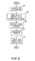
- the user command to regenerate the model includes an indication of a modified command. That command is identified in the routine of Fig. 8 by its command number I. Command number I is less than or equal to T, wherein T represents the total number of commands executed in the generating the model.
- the I-th command is identified, and then the method proceeds to step 122, wherein the data storing the tags for the model entities is checked to determine which pre-existing entities should be included in the model to be regenerated with the I-th command.
- the data storing the tags for the model entities is checked to determine which pre-existing entities should be included in the model to be regenerated with the I-th command.
- all of the entities created before the execution of the I-th command need not be regenerated, and can simply be included in the resulting model, along with the newly created entities formed by the execution of the modified I-th command and all subsequent commands.
- step 122 the method checks the tag entities to identify tags having an activation number less than I, and a deactivation number greater than or equal to I, and then proceeds to step 124, wherein the model is recreated with the existing entities having the tags identified in step 122. Thereafter, in step 126, commands I-T are regenerated to update the model in the manner requested by the user in the call to regeneration routine. Finally, in step 128, new tags are created for the entities created or updated by the regeneration of commands I-T.
- step 140 the user is prompted to accept either the regenerated version or the original version. This choice is useful because a minor dimensional change may ultimately lead to undesirable consequences in other parts of the model. Thus, the user has the option of maintaining the original version of the model.
- step 142 When the regenerated model is selected (step 142), the user is prompted to decide whether to save the original version (step 144).
- step 146 a determination is made as to whether the original version is to be saved, because when it is, the system may assign two different version numbers to a single entity. For example, if regeneration is begun at a command twenty, all entities that were created by commands one through nineteen and were never deactivated would be included in both the original and regenerated versions of the model. However, some of entities created by commands one through nineteen may be altered in the regenerated version. For example, in one version of the model a certain dimension (e.g., the radius of bore 32 in Fig. 3) may have one value, while in another version it may have a different value.
- a version number can be assigned to each version of the model, and each model entity can be identified as belonging to one or more versions.
- step 146 When it is determined at step 146 that the original version is to be saved, the method proceeds to step 148, wherein all the entities that are common to both the original and regenerated versions are assigned two version numbers, indicating that those entities belong to both versions. Conversely, in step 150, the entities that differ in the original and regenerated versions are separately defined, each with a different version number indicating that those entities belong to only one version of the model. Thus, the system indicates that all of the different entities belong to either the original or regenerated versions, while all the common entities are indicated as belonging to both versions.
- step 146 When it is determined at step 146 that the original version is not to be saved, separate versions for the model are not created. Therefore, the method simply terminates.
- the method proceeds in a similar manner when it is determined in step 142 that the regenerated version of the model has not been selected by the user.
- the method proceeds to step 152, wherein the user is prompted to determine whether the regenerated version of the model should be saved.
- the method proceeds to steps 148-150, wherein each entity is provided with one or more version numbers in the manner described above. Conversely, when it is determined at step 154 that the regenerated version is not to be saved, separate versions for the model are not created and the method simply terminates.
- the history module 18 (Fig. 1) also saves information that indicates how many times a model and individual model entities have been regenerated. Each time the model is regenerated, this information is updated. The same information can also be obtained by counting a number of versions for the model or any particular model entity.
- the CAD system of the present invention can go directly to the state of the model before a command at which a user wants to begin regeneration. While the example which has been used here is very simple, it should be understood that a model, e.g., an automobile door or transmission, may be produced from thousands of commands, and may have thousands of entities. Thus, it should be apparent that when commands having a high command sequence number are changed, the time savings over prior art systems can be very significant. In one test that has been conducted, a model was produced with seventy-seven commands. It was found that its regeneration might take as long as fifteen minutes using a typical prior art system. According to the present invention, however, regeneration was performed in as little as sixty seconds or less if one of the more recent commands is changed or undone. When command fifty was changed or undone, the savings was still more than 33%.
- a user can save multiple versions of a model without storing large quantities of repetitive data.
- a user can obtain the state of one of a number of different models at any given time, thus substantially reducing repetitive tasks.
Landscapes
- Physics & Mathematics (AREA)
- Engineering & Computer Science (AREA)
- Computer Graphics (AREA)
- Geometry (AREA)
- Software Systems (AREA)
- General Physics & Mathematics (AREA)
- Theoretical Computer Science (AREA)
- Information Retrieval, Db Structures And Fs Structures Therefor (AREA)
- Numerical Control (AREA)
Applications Claiming Priority (2)
| Application Number | Priority Date | Filing Date | Title |
|---|---|---|---|
| US542453 | 1995-10-12 | ||
| US08/542,453 US5850535A (en) | 1995-10-12 | 1995-10-12 | Roll-back during regeneration on a computer-aided design system |
Publications (2)
| Publication Number | Publication Date |
|---|---|
| EP0768624A2 true EP0768624A2 (fr) | 1997-04-16 |
| EP0768624A3 EP0768624A3 (fr) | 1998-04-01 |
Family
ID=24163902
Family Applications (1)
| Application Number | Title | Priority Date | Filing Date |
|---|---|---|---|
| EP96401889A Withdrawn EP0768624A3 (fr) | 1995-10-12 | 1996-09-04 | Recul pendant le régénération dans un système C.A.O. (Conception Assistée pour Ordinateur) |
Country Status (2)
| Country | Link |
|---|---|
| US (1) | US5850535A (fr) |
| EP (1) | EP0768624A3 (fr) |
Cited By (7)
| Publication number | Priority date | Publication date | Assignee | Title |
|---|---|---|---|---|
| EP0947961A2 (fr) * | 1998-04-03 | 1999-10-06 | Toyota Caelum Incorporated | Système de conception assistée par ordinateur basée sur la conception en equipe |
| WO2001042995A2 (fr) * | 1999-12-13 | 2001-06-14 | Amada Company, Limited | Logiciel d'esquisse |
| EP1191483A2 (fr) * | 2000-09-25 | 2002-03-27 | Toyota Jidosha Kabushiki Kaisha | Système et procédé de conception assistée par ordinateur pour la modification d'un objet |
| WO2006130653A2 (fr) * | 2005-06-01 | 2006-12-07 | Siemens Product Lifecycle Management Software Inc. | Liaisons effectuées à l'aide d'une fonction retour |
| US7398129B2 (en) | 2004-10-07 | 2008-07-08 | Amada Company, Limited | Representation of sheet metal part models |
| US7539680B2 (en) * | 2002-05-10 | 2009-05-26 | Lsi Corporation | Revision control for database of evolved design |
| US7558427B2 (en) | 2004-07-22 | 2009-07-07 | Siemens Aktiengesellschaft | Method for analyzing image data |
Families Citing this family (36)
| Publication number | Priority date | Publication date | Assignee | Title |
|---|---|---|---|---|
| JP3241266B2 (ja) * | 1996-06-03 | 2001-12-25 | 本田技研工業株式会社 | 3次元cadシステム |
| US5990894A (en) * | 1997-06-16 | 1999-11-23 | Sun Microsystems, Inc. | Method for implementing the power function DP and computer graphics system employing the same |
| FR2765983B1 (fr) * | 1997-07-11 | 2004-12-03 | France Telecom | Signal de donnees de modification d'une scene graphique, procede et dispositif correspondants |
| US6445974B1 (en) * | 1998-12-30 | 2002-09-03 | Intergraph Corporation | CAD-neutral application programming interface |
| US6473673B1 (en) | 1999-05-24 | 2002-10-29 | Parametric Technology Corporation | Method and system for management of heterogeneous assemblies |
| US7768526B2 (en) * | 2000-11-15 | 2010-08-03 | Autodesk, Inc. | Graphical object generation and regeneration |
| JP2002215696A (ja) * | 2001-01-19 | 2002-08-02 | Komatsu Ltd | 3次元cadシステム |
| US7043481B2 (en) * | 2001-06-01 | 2006-05-09 | Thought, Inc. | System, method and software for creating, maintaining, navigating or manipulating complex data objects and their data relationships |
| US7392390B2 (en) | 2001-12-12 | 2008-06-24 | Valve Corporation | Method and system for binding kerberos-style authenticators to single clients |
| US6996817B2 (en) * | 2001-12-12 | 2006-02-07 | Valve Corporation | Method and system for upgrading and rolling back versions |
| US7243226B2 (en) | 2001-12-12 | 2007-07-10 | Valve Corporation | Method and system for enabling content security in a distributed system |
| US7290040B2 (en) | 2001-12-12 | 2007-10-30 | Valve Corporation | Method and system for load balancing an authentication system |
| US7373406B2 (en) | 2001-12-12 | 2008-05-13 | Valve Corporation | Method and system for effectively communicating file properties and directory structures in a distributed file system |
| US8108687B2 (en) | 2001-12-12 | 2012-01-31 | Valve Corporation | Method and system for granting access to system and content |
| US7089160B2 (en) * | 2002-01-08 | 2006-08-08 | International Business Machines Corporation | Model for modifying drill data to predict hole locations in a panel structure |
| JP4822863B2 (ja) * | 2006-02-08 | 2011-11-24 | 富士通株式会社 | 数値解析データ作成方法及び装置並びにプログラム及び記憶媒体 |
| US9110934B2 (en) | 2006-06-02 | 2015-08-18 | International Business Machines Corporation | System and method for delivering an integrated server administration platform |
| US20070292833A1 (en) | 2006-06-02 | 2007-12-20 | International Business Machines Corporation | System and Method for Creating, Executing and Searching through a form of Active Web-Based Content |
| US20070282876A1 (en) * | 2006-06-05 | 2007-12-06 | Yixin Diao | Method for service offering comparitive it management activity complexity benchmarking |
| US20070282653A1 (en) * | 2006-06-05 | 2007-12-06 | Ellis Edward Bishop | Catalog based services delivery management |
| US8554596B2 (en) * | 2006-06-05 | 2013-10-08 | International Business Machines Corporation | System and methods for managing complex service delivery through coordination and integration of structured and unstructured activities |
| US20070282776A1 (en) * | 2006-06-05 | 2007-12-06 | International Business Machines Corporation | Method and system for service oriented collaboration |
| US8468042B2 (en) | 2006-06-05 | 2013-06-18 | International Business Machines Corporation | Method and apparatus for discovering and utilizing atomic services for service delivery |
| US20070282470A1 (en) * | 2006-06-05 | 2007-12-06 | International Business Machines Corporation | Method and system for capturing and reusing intellectual capital in IT management |
| US7877284B2 (en) | 2006-06-05 | 2011-01-25 | International Business Machines Corporation | Method and system for developing an accurate skills inventory using data from delivery operations |
| US8001068B2 (en) * | 2006-06-05 | 2011-08-16 | International Business Machines Corporation | System and method for calibrating and extrapolating management-inherent complexity metrics and human-perceived complexity metrics of information technology management |
| KR101185093B1 (ko) * | 2008-12-19 | 2012-09-21 | 한국전자통신연구원 | Autosar 응용 소프트웨어의 소프트웨어 구조 모델링 도구를 위한 프로젝트 관리 장치 및 방법 |
| US8914256B1 (en) | 2009-01-21 | 2014-12-16 | Bentley Systems, Incorporated | Analytical space model for interfacing with energy analysis, facilities management or other analysis applications |
| US20110307281A1 (en) * | 2010-06-11 | 2011-12-15 | Satterfield & Pontikes Construction, Inc. | Model inventory manager |
| EP2474929A1 (fr) | 2010-12-30 | 2012-07-11 | Dassault Systèmes | Actualisation d'objets modelés |
| EP2474930B1 (fr) | 2010-12-30 | 2018-10-24 | Dassault Systèmes | Actualisation d'un objet modelé |
| EP2474928A1 (fr) | 2010-12-30 | 2012-07-11 | Dassault Systèmes | Fusion d'objets modelés |
| US9841956B2 (en) | 2011-01-31 | 2017-12-12 | Sap Se | User interface style guide compliance reporting |
| US9052845B2 (en) * | 2011-01-31 | 2015-06-09 | Sap Se | Unified interface for meta model checking, modifying, and reporting |
| US9459846B2 (en) | 2011-01-31 | 2016-10-04 | Sap Se | User interface style guide compliance |
| US9734266B2 (en) * | 2013-03-15 | 2017-08-15 | IronCAD, LLC | Computer-aided design multi-user design negotiation system and method thereof |
Citations (1)
| Publication number | Priority date | Publication date | Assignee | Title |
|---|---|---|---|---|
| FR2636753A1 (fr) * | 1988-09-20 | 1990-03-23 | Ticoh Cy Ltd | Procede permettant d'annuler une operation a l'aide d'une relation de dependance entre des relations |
Family Cites Families (7)
| Publication number | Priority date | Publication date | Assignee | Title |
|---|---|---|---|---|
| US4864497A (en) * | 1988-04-13 | 1989-09-05 | Digital Equipment Corporation | Method of integrating software application programs using an attributive data model database |
| US5019961A (en) * | 1989-04-05 | 1991-05-28 | Cadware, Inc. | Computer apparatus and method for logical modelling |
| US5893117A (en) * | 1990-08-17 | 1999-04-06 | Texas Instruments Incorporated | Time-stamped database transaction and version management system |
| US5287501A (en) * | 1991-07-11 | 1994-02-15 | Digital Equipment Corporation | Multilevel transaction recovery in a database system which loss parent transaction undo operation upon commit of child transaction |
| JP2835791B2 (ja) * | 1991-09-30 | 1998-12-14 | 富士通株式会社 | 図形処理装置 |
| JP3793226B2 (ja) * | 1992-12-23 | 2006-07-05 | オブジェクト テクノロジー ライセンシング コーポレイション | アトミック・コマンド・システム |
| US5572637A (en) * | 1994-06-30 | 1996-11-05 | International Business Machines Corporation | Process for merging CAD vector files and automatically removing duplicate and obsolete patterns |
-
1995
- 1995-10-12 US US08/542,453 patent/US5850535A/en not_active Expired - Lifetime
-
1996
- 1996-09-04 EP EP96401889A patent/EP0768624A3/fr not_active Withdrawn
Patent Citations (1)
| Publication number | Priority date | Publication date | Assignee | Title |
|---|---|---|---|---|
| FR2636753A1 (fr) * | 1988-09-20 | 1990-03-23 | Ticoh Cy Ltd | Procede permettant d'annuler une operation a l'aide d'une relation de dependance entre des relations |
Non-Patent Citations (3)
| Title |
|---|
| BLIN M -J ET AL: "A model of configurations for hardware/software system deliveries" TOULOSE '92. FIFTH INTERNATIONAL CONFERENCE. SOFTWARE ENGINEERING AND ITS APPLICATIONS PROCEEDINGS, TOULOUSE, FRANCE, 7-11 DEC. 1992, ISBN 2-906899-81-X, 1992, NANTERRE, FRANCE, EC2, FRANCE, pages 795-806, XP002053917 * |
| KAFER W ET AL: "Mapping a version model to a complex-object data model" EIGHTH INTERNATIONAL CONFERENCE ON DATA ENGINEERING (CAT. NO.92CH3097-3), TEMPE, AZ, USA, 2-3 FEB. 1992, ISBN 0-8186-2545-7, 1992, LOS ALAMITOS, CA, USA, IEEE COMPUT. SOC. PRESS, USA, pages 348-357, XP002053916 * |
| TORIYA H ET AL: "UNDO AND REDO OPERATIONS FOR SOLID MODELING" IEEE COMPUTER GRAPHICS AND APPLICATIONS, vol. 6, no. 4, April 1986, pages 35-42, XP000051330 * |
Cited By (13)
| Publication number | Priority date | Publication date | Assignee | Title |
|---|---|---|---|---|
| EP0947961A2 (fr) * | 1998-04-03 | 1999-10-06 | Toyota Caelum Incorporated | Système de conception assistée par ordinateur basée sur la conception en equipe |
| EP0947961A3 (fr) * | 1998-04-03 | 2002-11-13 | Toyota Caelum Incorporated | Système de conception assistée par ordinateur basée sur la conception en equipe |
| US6771260B1 (en) | 1999-12-13 | 2004-08-03 | Amada Company, Limited | Sketcher |
| WO2001042995A2 (fr) * | 1999-12-13 | 2001-06-14 | Amada Company, Limited | Logiciel d'esquisse |
| WO2001042995A3 (fr) * | 1999-12-13 | 2002-06-20 | Amada Co Ltd | Logiciel d'esquisse |
| EP1191483A3 (fr) * | 2000-09-25 | 2005-01-12 | Toyota Jidosha Kabushiki Kaisha | Système et procédé de conception assistée par ordinateur pour la modification d'un objet |
| EP1191483A2 (fr) * | 2000-09-25 | 2002-03-27 | Toyota Jidosha Kabushiki Kaisha | Système et procédé de conception assistée par ordinateur pour la modification d'un objet |
| US7539680B2 (en) * | 2002-05-10 | 2009-05-26 | Lsi Corporation | Revision control for database of evolved design |
| US7558427B2 (en) | 2004-07-22 | 2009-07-07 | Siemens Aktiengesellschaft | Method for analyzing image data |
| US7398129B2 (en) | 2004-10-07 | 2008-07-08 | Amada Company, Limited | Representation of sheet metal part models |
| WO2006130653A2 (fr) * | 2005-06-01 | 2006-12-07 | Siemens Product Lifecycle Management Software Inc. | Liaisons effectuées à l'aide d'une fonction retour |
| WO2006130653A3 (fr) * | 2005-06-01 | 2007-03-15 | Ugs Corp | Liaisons effectuées à l'aide d'une fonction retour |
| US8654145B2 (en) | 2005-06-01 | 2014-02-18 | Siemens Product Lifecycle Management Software Inc. | Binding using rollback |
Also Published As
| Publication number | Publication date |
|---|---|
| US5850535A (en) | 1998-12-15 |
| EP0768624A3 (fr) | 1998-04-01 |
Similar Documents
| Publication | Publication Date | Title |
|---|---|---|
| US5850535A (en) | Roll-back during regeneration on a computer-aided design system | |
| US5689711A (en) | Method and apparatus for representing data dependencies in software modeling systems | |
| RU2119188C1 (ru) | Способ компьютерного управления построением изделий | |
| CA1316262C (fr) | Outil de gestion de versions de module | |
| US5930806A (en) | Method and system for data migration from network database to relational database | |
| US5847956A (en) | Automatic trimming of geometric objects in CAD/CAM systems | |
| US5488722A (en) | System and method for automating implementation and execution of constraint most likely to be violated in a database | |
| JP2003509740A (ja) | コンピュータ支援設計システム間のデータ交換 | |
| JPH06259400A (ja) | 複雑なシステムのシミュレーション操作方法 | |
| AU4098700A (en) | Circuit arrangement for measuring the resistances of a pressure-sensitive resistance mat | |
| US5561794A (en) | Early commit optimistic projection-based computer database protocol | |
| JPH0475134A (ja) | ファイル管理装置 | |
| US5394546A (en) | Database management system and method of extending system functions | |
| JPH0683598A (ja) | ジョブフロー仕様書自動作成方法 | |
| US6571146B1 (en) | Method for updating feature recipes in a history-based solid model | |
| EP1203319B1 (fr) | Procede d'attribution d'une identite a un objet contenu dans une base de donnees | |
| Rolland et al. | Tools for information system dynamics management | |
| WO1995032476A1 (fr) | Systeme et procede permettant de creer des configurations de conception et de commander l'application d'outils de conception multiples | |
| US20050246160A1 (en) | Information generation system for product formation | |
| JP2800592B2 (ja) | 加工図形データへの工具配置干渉チェック方法 | |
| US6243848B1 (en) | Process for analyzing complex structures and system for implementing a process of this type | |
| EP1248189A1 (fr) | Procede et dispositif de reproduction de programme, et support de programme pour enregistrement de reproduction de programme | |
| Barley et al. | Executive-centred system design for CAD applications | |
| JPS6165333A (ja) | システム構造評価方式 | |
| JP2002108947A (ja) | 設計支援システム |
Legal Events
| Date | Code | Title | Description |
|---|---|---|---|
| PUAI | Public reference made under article 153(3) epc to a published international application that has entered the european phase |
Free format text: ORIGINAL CODE: 0009012 |
|
| AK | Designated contracting states |
Kind code of ref document: A2 Designated state(s): DE FR GB IT |
|
| PUAL | Search report despatched |
Free format text: ORIGINAL CODE: 0009013 |
|
| AK | Designated contracting states |
Kind code of ref document: A3 Designated state(s): DE FR GB IT |
|
| STAA | Information on the status of an ep patent application or granted ep patent |
Free format text: STATUS: THE APPLICATION IS DEEMED TO BE WITHDRAWN |
|
| 18D | Application deemed to be withdrawn |
Effective date: 20000401 |