EP0768107B1 - Honeycomb heater with parallel circuits - Google Patents
Honeycomb heater with parallel circuits Download PDFInfo
- Publication number
- EP0768107B1 EP0768107B1 EP96307415A EP96307415A EP0768107B1 EP 0768107 B1 EP0768107 B1 EP 0768107B1 EP 96307415 A EP96307415 A EP 96307415A EP 96307415 A EP96307415 A EP 96307415A EP 0768107 B1 EP0768107 B1 EP 0768107B1
- Authority
- EP
- European Patent Office
- Prior art keywords
- honeycomb
- slits
- honeycomb structure
- heater
- honeycomb heater
- Prior art date
- Legal status (The legal status is an assumption and is not a legal conclusion. Google has not performed a legal analysis and makes no representation as to the accuracy of the status listed.)
- Expired - Lifetime
Links
- 239000000463 material Substances 0.000 claims description 11
- 239000003054 catalyst Substances 0.000 claims description 9
- 239000011248 coating agent Substances 0.000 claims description 4
- 238000000576 coating method Methods 0.000 claims description 4
- 229910000510 noble metal Inorganic materials 0.000 claims description 4
- 239000010935 stainless steel Substances 0.000 claims description 4
- 229910001220 stainless steel Inorganic materials 0.000 claims description 4
- 229910052763 palladium Inorganic materials 0.000 claims description 3
- 229910052697 platinum Inorganic materials 0.000 claims description 3
- 229910052703 rhodium Inorganic materials 0.000 claims description 3
- 229910000859 α-Fe Inorganic materials 0.000 claims description 3
- 229910003158 γ-Al2O3 Inorganic materials 0.000 claims description 3
- 239000000843 powder Substances 0.000 description 8
- 229910052751 metal Inorganic materials 0.000 description 7
- 239000002184 metal Substances 0.000 description 7
- 230000003197 catalytic effect Effects 0.000 description 6
- 238000010438 heat treatment Methods 0.000 description 6
- 230000001590 oxidative effect Effects 0.000 description 6
- 238000005192 partition Methods 0.000 description 6
- 238000000034 method Methods 0.000 description 5
- 238000000746 purification Methods 0.000 description 5
- 230000005611 electricity Effects 0.000 description 4
- 238000010304 firing Methods 0.000 description 4
- 239000007789 gas Substances 0.000 description 4
- 239000011230 binding agent Substances 0.000 description 3
- 230000000052 comparative effect Effects 0.000 description 3
- 239000011148 porous material Substances 0.000 description 3
- 239000000126 substance Substances 0.000 description 3
- GWEVSGVZZGPLCZ-UHFFFAOYSA-N Titan oxide Chemical compound O=[Ti]=O GWEVSGVZZGPLCZ-UHFFFAOYSA-N 0.000 description 2
- PNEYBMLMFCGWSK-UHFFFAOYSA-N aluminium oxide Inorganic materials [O-2].[O-2].[O-2].[Al+3].[Al+3] PNEYBMLMFCGWSK-UHFFFAOYSA-N 0.000 description 2
- 230000015572 biosynthetic process Effects 0.000 description 2
- 230000003247 decreasing effect Effects 0.000 description 2
- 238000001125 extrusion Methods 0.000 description 2
- 229910044991 metal oxide Inorganic materials 0.000 description 2
- 150000004706 metal oxides Chemical class 0.000 description 2
- 239000000203 mixture Substances 0.000 description 2
- 230000003647 oxidation Effects 0.000 description 2
- 238000007254 oxidation reaction Methods 0.000 description 2
- 230000035939 shock Effects 0.000 description 2
- XLYOFNOQVPJJNP-UHFFFAOYSA-N water Substances O XLYOFNOQVPJJNP-UHFFFAOYSA-N 0.000 description 2
- WRIDQFICGBMAFQ-UHFFFAOYSA-N (E)-8-Octadecenoic acid Natural products CCCCCCCCCC=CCCCCCCC(O)=O WRIDQFICGBMAFQ-UHFFFAOYSA-N 0.000 description 1
- LQJBNNIYVWPHFW-UHFFFAOYSA-N 20:1omega9c fatty acid Natural products CCCCCCCCCCC=CCCCCCCCC(O)=O LQJBNNIYVWPHFW-UHFFFAOYSA-N 0.000 description 1
- QSBYPNXLFMSGKH-UHFFFAOYSA-N 9-Heptadecensaeure Natural products CCCCCCCC=CCCCCCCCC(O)=O QSBYPNXLFMSGKH-UHFFFAOYSA-N 0.000 description 1
- UFHFLCQGNIYNRP-UHFFFAOYSA-N Hydrogen Chemical compound [H][H] UFHFLCQGNIYNRP-UHFFFAOYSA-N 0.000 description 1
- ZQPPMHVWECSIRJ-UHFFFAOYSA-N Oleic acid Natural products CCCCCCCCC=CCCCCCCCC(O)=O ZQPPMHVWECSIRJ-UHFFFAOYSA-N 0.000 description 1
- 239000005642 Oleic acid Substances 0.000 description 1
- 239000004372 Polyvinyl alcohol Substances 0.000 description 1
- 102100025490 Slit homolog 1 protein Human genes 0.000 description 1
- 101710123186 Slit homolog 1 protein Proteins 0.000 description 1
- 229910045601 alloy Inorganic materials 0.000 description 1
- 239000000956 alloy Substances 0.000 description 1
- 239000003963 antioxidant agent Substances 0.000 description 1
- 230000003078 antioxidant effect Effects 0.000 description 1
- 229910001566 austenite Inorganic materials 0.000 description 1
- 239000010953 base metal Substances 0.000 description 1
- 238000005219 brazing Methods 0.000 description 1
- 239000003990 capacitor Substances 0.000 description 1
- 239000000919 ceramic Substances 0.000 description 1
- 238000006243 chemical reaction Methods 0.000 description 1
- 229910052804 chromium Inorganic materials 0.000 description 1
- 238000001816 cooling Methods 0.000 description 1
- 229910052802 copper Inorganic materials 0.000 description 1
- 229910052593 corundum Inorganic materials 0.000 description 1
- 230000007547 defect Effects 0.000 description 1
- 229910003460 diamond Inorganic materials 0.000 description 1
- 239000010432 diamond Substances 0.000 description 1
- 238000011156 evaluation Methods 0.000 description 1
- 230000002349 favourable effect Effects 0.000 description 1
- 239000011888 foil Substances 0.000 description 1
- 238000000227 grinding Methods 0.000 description 1
- 230000020169 heat generation Effects 0.000 description 1
- 239000001257 hydrogen Substances 0.000 description 1
- 229910052739 hydrogen Inorganic materials 0.000 description 1
- 238000010348 incorporation Methods 0.000 description 1
- 239000012212 insulator Substances 0.000 description 1
- QXJSBBXBKPUZAA-UHFFFAOYSA-N isooleic acid Natural products CCCCCCCC=CCCCCCCCCC(O)=O QXJSBBXBKPUZAA-UHFFFAOYSA-N 0.000 description 1
- 238000004519 manufacturing process Methods 0.000 description 1
- 150000002739 metals Chemical class 0.000 description 1
- 229920000609 methyl cellulose Polymers 0.000 description 1
- 239000001923 methylcellulose Substances 0.000 description 1
- 235000010981 methylcellulose Nutrition 0.000 description 1
- 238000002156 mixing Methods 0.000 description 1
- 229910052759 nickel Inorganic materials 0.000 description 1
- ZQPPMHVWECSIRJ-KTKRTIGZSA-N oleic acid Chemical compound CCCCCCCC\C=C/CCCCCCCC(O)=O ZQPPMHVWECSIRJ-KTKRTIGZSA-N 0.000 description 1
- 238000007747 plating Methods 0.000 description 1
- 229920002451 polyvinyl alcohol Polymers 0.000 description 1
- 238000009704 powder extrusion Methods 0.000 description 1
- 238000004663 powder metallurgy Methods 0.000 description 1
- 230000002040 relaxant effect Effects 0.000 description 1
- 230000008646 thermal stress Effects 0.000 description 1
- 238000003466 welding Methods 0.000 description 1
- 229910001845 yogo sapphire Inorganic materials 0.000 description 1
Images


Classifications
-
- B01J35/33—
-
- B01J35/56—
-
- F—MECHANICAL ENGINEERING; LIGHTING; HEATING; WEAPONS; BLASTING
- F01—MACHINES OR ENGINES IN GENERAL; ENGINE PLANTS IN GENERAL; STEAM ENGINES
- F01N—GAS-FLOW SILENCERS OR EXHAUST APPARATUS FOR MACHINES OR ENGINES IN GENERAL; GAS-FLOW SILENCERS OR EXHAUST APPARATUS FOR INTERNAL COMBUSTION ENGINES
- F01N3/00—Exhaust or silencing apparatus having means for purifying, rendering innocuous, or otherwise treating exhaust
- F01N3/08—Exhaust or silencing apparatus having means for purifying, rendering innocuous, or otherwise treating exhaust for rendering innocuous
- F01N3/10—Exhaust or silencing apparatus having means for purifying, rendering innocuous, or otherwise treating exhaust for rendering innocuous by thermal or catalytic conversion of noxious components of exhaust
- F01N3/18—Exhaust or silencing apparatus having means for purifying, rendering innocuous, or otherwise treating exhaust for rendering innocuous by thermal or catalytic conversion of noxious components of exhaust characterised by methods of operation; Control
- F01N3/20—Exhaust or silencing apparatus having means for purifying, rendering innocuous, or otherwise treating exhaust for rendering innocuous by thermal or catalytic conversion of noxious components of exhaust characterised by methods of operation; Control specially adapted for catalytic conversion ; Methods of operation or control of catalytic converters
- F01N3/2006—Periodically heating or cooling catalytic reactors, e.g. at cold starting or overheating
- F01N3/2013—Periodically heating or cooling catalytic reactors, e.g. at cold starting or overheating using electric or magnetic heating means
-
- F—MECHANICAL ENGINEERING; LIGHTING; HEATING; WEAPONS; BLASTING
- F01—MACHINES OR ENGINES IN GENERAL; ENGINE PLANTS IN GENERAL; STEAM ENGINES
- F01N—GAS-FLOW SILENCERS OR EXHAUST APPARATUS FOR MACHINES OR ENGINES IN GENERAL; GAS-FLOW SILENCERS OR EXHAUST APPARATUS FOR INTERNAL COMBUSTION ENGINES
- F01N2330/00—Structure of catalyst support or particle filter
- F01N2330/02—Metallic plates or honeycombs, e.g. superposed or rolled-up corrugated or otherwise deformed sheet metal
- F01N2330/04—Methods of manufacturing
-
- F—MECHANICAL ENGINEERING; LIGHTING; HEATING; WEAPONS; BLASTING
- F01—MACHINES OR ENGINES IN GENERAL; ENGINE PLANTS IN GENERAL; STEAM ENGINES
- F01N—GAS-FLOW SILENCERS OR EXHAUST APPARATUS FOR MACHINES OR ENGINES IN GENERAL; GAS-FLOW SILENCERS OR EXHAUST APPARATUS FOR INTERNAL COMBUSTION ENGINES
- F01N2330/00—Structure of catalyst support or particle filter
- F01N2330/30—Honeycomb supports characterised by their structural details
- F01N2330/34—Honeycomb supports characterised by their structural details with flow channels of polygonal cross section
-
- Y—GENERAL TAGGING OF NEW TECHNOLOGICAL DEVELOPMENTS; GENERAL TAGGING OF CROSS-SECTIONAL TECHNOLOGIES SPANNING OVER SEVERAL SECTIONS OF THE IPC; TECHNICAL SUBJECTS COVERED BY FORMER USPC CROSS-REFERENCE ART COLLECTIONS [XRACs] AND DIGESTS
- Y02—TECHNOLOGIES OR APPLICATIONS FOR MITIGATION OR ADAPTATION AGAINST CLIMATE CHANGE
- Y02T—CLIMATE CHANGE MITIGATION TECHNOLOGIES RELATED TO TRANSPORTATION
- Y02T10/00—Road transport of goods or passengers
- Y02T10/10—Internal combustion engine [ICE] based vehicles
- Y02T10/12—Improving ICE efficiencies
Definitions
- the present invention relates to an electrically heatable honeycomb heater suitably used for the purification of automobile exhaust gas, etc.
- a technique is known in which when a catalytic convertor is used in automobiles, etc. for purification of the exhaust gas emitted therefrom, an electrically heatable heater is used, in combination with the catalytic convertor, to heat the convertor to its operating temperature as quickly as possible.
- honeycomb heater comprising a honeycomb structure made of an electroconductive material and electrodes fitted thereto for electrification thereof.
- slits are generally formed in the honeycomb structure for adjustment of the amount of heat generated in the structure.
- slits 1 are formed in a honeycomb structure 5 in such a manner that they extend alternately from the opposing two halves of the circumference of the honeycomb structure 5, divided by a virtual plane including electrodes 3; thereby, the length of flow path of electricity in the honeycomb structure 5 is set appropriately to adjust the electric resistance of the honeycomb structure 5 and achieve heat generation of intended amount.
- Arrangements of this type are described in EP 485 179 A and EP 638 710 A (both to NGK Insulators).
- the honeycomb heater In using such a honeycomb heater in an automobile for the purification of the exhaust gas emitted therefrom, there is used, as the electric source of the honeycomb heater, an alternator or a battery.
- an alternator or a battery When a battery is used, it is impossible to allow the honeycomb heater to have a resistance higher than a certain level owing to the limitation of electric power to be consumed. In this case, therefore, the number of slits formed in the honeycomb structure is small; the distance between adjacent slits is large; and the number of cells between adjacent slits, i.e. the number of cells (passages) present in the shortest distance between adjacent slits is large.
- EP 0 465 184 A describes honeycomb heaters in which the electrical resistance is controlled by means of slits to achieve a current density of 5A/mm 2 or above.
- EP 661 097 A describes arrangements of resistance-adjusting slits in honeycomb heaters which allow certain regions of the heaters to be heated selectively in preference to other regions.
- EP 661 421 A proposes incorporation of orifices with a larger hydraulic diameter than the cells of the honeycomb in order to regulate the relative rates of heating of different regions of the heater.
- the present invention has been made in view of the above-mentioned problems of the prior art.
- the main object of the present invention is to provide a low-resistance honeycomb heater with slits, which has excellent durability to repeated electrification and which can be suitably used with a battery.
- a honeycomb heater comprising a honeycomb structure made of an electroconductive material and electrodes fitted thereto for electrification thereof, wherein slits for resistance adjustment are formed in the honeycomb structure in such a manner that parallel electric circuits are formed in the honeycomb structure upon electrification of the structure.
- Fig. 1(A) is a drawing showing an example of the honeycomb heater according to the present invention.
- Fig. 1(B) is a circuit drawing when the honeycomb heater is connected to a battery.
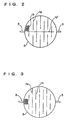
- Fig. 2 is a drawing showing an example of the honeycomb heater according to the present invention.
- Fig. 3 is a drawing showing an example of the honeycomb heater according to the present invention.
- Fig. 4 is a drawing showing an example of the honeycomb heater according to the present invention.
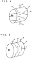
- Fig. 5 is a drawing showing an example of the honeycomb heater according to the present invention.
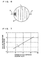
- Fig. 6 is a drawing showing a conventional honeycomb heater.
- Fig. 7 is a graph showing the result of a study made on the relation between the number of cells between adjacent slits and the ratio of temperature elevation rates.
- Fig. 8 is a drawing showing the position at which the temperature elevation rate of slit end was measured.
- Fig. 9 is a drawing showing a state in which rupture has occurred in part of a conventional honeycomb heater.
- Fig. 10 a drawing showing a state in which rupture has occurred in part of a honeycomb heater according to the present invention.
- a honeycomb heater with slits formed in the honeycomb structure In a honeycomb heater with slits formed in the honeycomb structure, the current concentration occurring in the vicinity of each slit end of the honeycomb structure can be effectively relaxed by decreasing the number of cells between adjacent slits and increasing the number of slits formed in the honeycomb structure.
- the ratio of temperature elevation rates is a value calculated from the following formula, using the temperature elevation rate at slit end and the temperature elevation rate at honeycomb structure center both measured for 5 seconds from the start of electrification of honeycomb heater at 2.0 kW (an electric power supplied to the honeycomb structure).
- the temperature elevation rate at slit end was measured at the cell A contacting with the end of slit 1, shown in the partially enlarged view of Fig. 8.
- Ratio of temperature elevation rates (temperature elevation rate at slit end)/ (temperature elevation rate at honeycomb structure center)
- slits were formed in the honeycomb structure of a honeycomb heater so that parallel circuits are formed in the honeycomb structure.
- the sum of reciprocal numbers of resistances of individual circuits becomes the reciprocal number of total resistance. Therefore, in the present invention, even when the number of cells between adjacent slits is decreased and the flow path of electricity in each circuit is made long, the total resistance of honeycomb structure can be kept relatively low. Hence, in the present honeycomb heater, the number of cells between adjacent slits can be made small while the total resistance is made small so as to be used with a battery in automobiles, and current concentration in the vicinity of each slit end can be relaxed; thus, the present honeycomb heater has excellent durability to repeated electrification.
- slits each with one end reaching the circumference of the honeycomb structure and other end not reaching the circumference of the honeycomb structure and slits each with both ends not reaching the circumference of the honeycomb structure are made in combination to form parallel electric circuits in the honeycomb structure.
- Fig. 1(A) shows such an example.
- a honeycomb structure 5 provided with electrodes 3 for electricity supply there are alternately formed a slit 1a with one end reaching the circumference of the honeycomb structure and other end not reaching the circumference and a slit 1b with both ends not reaching the circumference.
- Fig. 1(B) which is a circuit drawing when such a honeycomb heater is connected to a battery
- two circuits are formed in the honeycomb structure.
- R1 the resistance of each circuit
- the total resistance of the honeycomb structure becomes half of the resistance R1 of each circuit based on the calculation made using the following formula.
- Fig. 2 shows other example of the present honeycomb heater, wherein a slit 1b' is formed, in addition to the slits shown in Fig. 1, so as to intersect slits 1b.
- the number of circuits formed in the honeycomb structure is not restricted to 2 as in Fig. 2 and Fig. 3 and may be larger.
- the present honeycomb heater of Fig. 3 three circuits are formed in the honeycomb structure 5 by a combination of slits 1a each with one end reaching the circumference of the honeycomb structure and other end not reaching the circumference and slits 1b each with both ends not reaching the circumference.
- This honeycomb heater can have an even smaller resistance than the present honeycomb heaters each having two circuits.
- Parallel circuits can also be formed in the honeycomb structure of the present honeycomb heater by forming slits in directions shown in Fig. 4 or 5.
- Fig. 4 is an example of the present honeycomb heater wherein slits are formed substantially in parallel to the cell axial direction and where two circuits are formed in the honeycomb structure 5 by a combination of slits 1c each with one end reaching the end of the structure and other end not reaching the end of the structure and slits 1d each with both ends not reaching the end of the structure.
- Fig. 5 is an example of the present honeycomb heater where slits are formed substantially perpendicularly to the cell axial direction and where two circuits are formed in the honeycomb structure 5 by a combination of slits le each with one end reaching the circumference of the structure and other end not reaching the circumference of the structure and slits if each with both ends not reaching the circumference of the structure.
- the total resistance is small and current concentration in the vicinity of each slit end can be relaxed, as mentioned above. Further, there is the following advantage. That is, in a conventional honeycomb heater with slits as shown in Fig. 9, when rupture takes place at one place between slits owing to the vibration during use, repeated electrification, etc., no heat is generated in any portion of the honeycomb heater; in contrast, in the present honeycomb heater as shown in Fig. 10, even when rupture takes place at one place between slits and one circuit is broken, if other circuit has no problem, the honeycomb heater can function although insufficiently.
- the electroconductive material constituting the honeycomb structure can be any of metals (e.g. ferrite type stainless steel and austenite type stainless steel), ceramics (e.g. perovskite type and SiC type), etc. Of these, ferrite type stainless steel is most preferred in view of the heat resistance and thermal shock resistance.
- metals e.g. ferrite type stainless steel and austenite type stainless steel
- ceramics e.g. perovskite type and SiC type
- ferrite type stainless steel is most preferred in view of the heat resistance and thermal shock resistance.
- the honeycomb structure may be produced by winding-up of metal foil or by powder metallurgy and extrusion, but the latter method is preferred for sufficient structural durability to avoid, in particular, a telescope phenomenon under severe conditions.
- the sectional shape (cell shape) of the passages is not particularly restricted and can be an arbitrary shape selected from a polygonal (e.g. square or hexagonal) shape, a circular shape, a corrugated shape, etc.; however, a flexible cell shape (e.g. a hexagonal shape) capable of relaxing the thermal stress applied is preferred in view of the thermal shock resistance to be possessed by the passages.
- a material metal powder is prepared using, for example, a Fe powder, an Al powder and a Cr powder, or a powder of an alloy thereof so that they give a desired composition.
- the material metal powder is then mixed with an organic binder (e.g. methyl cellulose or polyvinyl alcohol) and water.
- an organic binder e.g. methyl cellulose or polyvinyl alcohol
- the resulting mixture is subjected to extrusion to obtain a honeycomb body of desired shape.
- the material metal powder is mixed with an antioxidant (e.g. oleic acid) before being mixed with an organic binder and water, or that a material metal powder processed so as to have oxidation resistance is used.
- an antioxidant e.g. oleic acid
- the honeycomb body is fired at 1,000-1,400°C in a non-oxidizing atmosphere.
- a non-oxidizing atmosphere containing hydrogen is preferable because the organic binder is decomposed and removed by the help of the catalytic action of Fe, etc. and, as a result, an excellent sintered honeycomb body is obtained.
- the honeycomb body When the firing temperature is lower than 1,000°C, the honeycomb body is not sintered. When the firing temperature is higher than 1,400°C, the sintered body obtained is deformed.
- the surfaces of the partition walls and pores of the sintered honeycomb body are coated with a heat-resistant metal oxide.
- the coating of the surfaces with a heat-resistant metal oxide is preferably conducted by one of the following methods.
- the heat treatment temperature is preferably 900-1,100°C in view of the heat resistance and oxidation resistance.
- Formation of slits in the honeycomb structure produced by the above-mentioned extrusion method may be conducted after the firing of the honeycomb body, but is preferably conducted before the firing because slits are formed easily and defects such as cell breakage and the like are less likely to appear. Formation of slits can be conducted, for example, by grinding using a diamond saw.
- the electrodes are generally connected to an electric source such as battery, capacitor or the like via a switch or a controlling device.
- a catalyst layer containing a substance having a catalytic activity is loaded, by coating, on the partition walls of the honeycomb heater.
- the catalyst layer on the partition walls causes ignition when electrified and the reaction heat generated thereby accelerates the heating of the catalyst on the honeycomb heater or the light-off catalyst or main catalyst generally provided downstream of the honeycomb heater; thus, favorable purification ability is exhibited with a small electric power applied.
- the catalyst layer loaded on the partition walls of the honeycomb structure by coating comprises a carrier having a large surface area and a substance having a catalytic activity, loaded thereon.
- Typical examples of the carrier having a large surface area are ⁇ -Al 2 O 3 , TiO 2 , Sio 2 -Al 2 O 3 and perovskite.
- Examples of the substance having a catalytic activity are noble metals (e.g. Pt, Pd and Rh) and base metals (e.g. Cu, Ni, Cr and Co).
- a preferable catalyst layer comprises ⁇ -Al 2 O 3 (a carrier) and a noble metal (Pt, Pd or Rh) or a desired combination of these noble metals, loaded on the carrier.
- slits 1a and 1b were made in a honeycomb structure 5 made of an electroconductive material, having a diameter of 80 mm, a thickness of 12 mm, a hexagonal cell shape, a rib thickness of 0.01 cm (4 mil) and a cell density of 70 cells/cm 2 (450 cells/in. 2 ), so that two parallel circuits were formed in the honeycomb structure.
- the slits were made so that the total resistance of the honeycomb structure became 50 m ⁇ [this resistance was appropriate for use of the structure with a battery (an electric source) in automobiles] and the number of cells between two adjacent slits was constant (the cell number was always 4). Then, two electrode bolts were welded onto the circumference of the honeycomb structure to obtain a honeycomb heater.
- slits 1 were made in the same honeycomb structure 5 as used in Example, alternately from the two opposing circumferences of the honeycomb structure so that a single circuit was formed in the structure.
- the slits were made so that the total resistance of the honeycomb structure became 50 m ⁇ (this resistance was the same as in Example) and the number of cells between two adjacent slits was constant (the cell number was always 8 which was two times that of Example). Then, two electrode bolts were welded onto the circumference of the honeycomb structure to obtain a honeycomb heater.
- Example 2 The honeycomb heaters obtained in Example and Comparative Example were examined for durability to repeated electrification by the following method.
- Each honeycomb heater was electrified by feeding an electric power of 2.5 kW; electrification was stopped when the temperature of the center of the honeycomb structure reached 500°C; then, air cooling was conducted until the temperature of the honeycomb structure center came down to 80°C; and electrification was started again. This cycle was repeated until cell rupture occurred. The number of cycles up to the first cell rupture was measured.
- a honeycomb heater having parallel circuits according to the present invention (as shown in Fig. 1), as compared with a conventional honeycomb heater (as shown in Fig. 6), can have cells of smaller number between adjacent slits and can have excellent durability to repeated electrification.
- slits are made in the honeycomb structure so that parallel circuits are formed in the structure; thereby, the number of cells between adjacent slits can be made small (or, the distance between adjacent slits can be made small) while the total resistance of the structure is kept low. As a result, current concentration in the vicinity of each slit end is relaxed and the durability to repeated electrification is excellent.
Applications Claiming Priority (3)
| Application Number | Priority Date | Filing Date | Title |
|---|---|---|---|
| JP26525895 | 1995-10-13 | ||
| JP265258/95 | 1995-10-13 | ||
| JP7265258A JPH09103684A (ja) | 1995-10-13 | 1995-10-13 | 並列発熱型ハニカムヒーター |
Publications (2)
| Publication Number | Publication Date |
|---|---|
| EP0768107A1 EP0768107A1 (en) | 1997-04-16 |
| EP0768107B1 true EP0768107B1 (en) | 2002-06-05 |
Family
ID=17414737
Family Applications (1)
| Application Number | Title | Priority Date | Filing Date |
|---|---|---|---|
| EP96307415A Expired - Lifetime EP0768107B1 (en) | 1995-10-13 | 1996-10-11 | Honeycomb heater with parallel circuits |
Country Status (4)
| Country | Link |
|---|---|
| US (1) | US5852285A (ja) |
| EP (1) | EP0768107B1 (ja) |
| JP (1) | JPH09103684A (ja) |
| DE (1) | DE69621550T2 (ja) |
Families Citing this family (17)
| Publication number | Priority date | Publication date | Assignee | Title |
|---|---|---|---|---|
| US6287899B1 (en) * | 1998-12-31 | 2001-09-11 | Samsung Electronics Co., Ltd. | Thin film transistor array panels for a liquid crystal display and a method for manufacturing the same |
| DE102009018182A1 (de) * | 2009-04-22 | 2010-10-28 | Emitec Gesellschaft Für Emissionstechnologie Mbh | Mehrstufig beheizbarer Wabenkörper |
| JP2012072042A (ja) * | 2010-09-30 | 2012-04-12 | Tokyo Yogyo Co Ltd | 導電性炭化珪素質ハニカム構造体の製造方法 |
| JP2012072041A (ja) * | 2010-09-30 | 2012-04-12 | Tokyo Yogyo Co Ltd | 導電性ハニカム構造体 |
| JP5411887B2 (ja) | 2011-03-23 | 2014-02-12 | トヨタ自動車株式会社 | 触媒担持用構造体及び触媒コンバータ装置 |
| EP2689848B1 (en) * | 2011-03-25 | 2020-02-19 | NGK Insulators, Ltd. | Honeycomb structure |
| CN104245133B (zh) | 2012-03-30 | 2016-08-24 | 日本碍子株式会社 | 蜂窝结构体 |
| DE102012109391A1 (de) * | 2012-10-02 | 2014-04-03 | Emitec Gesellschaft Für Emissionstechnologie Mbh | Elektrisch beheizbarer, aus keramischem Material extrudierter Wabenkörper |
| EP3056274B1 (en) * | 2013-10-08 | 2020-02-12 | NGK Insulators, Ltd. | Honeycomb structure |
| EP3127611B1 (en) * | 2014-03-31 | 2018-12-26 | NGK Insulators, Ltd. | Honeycomb structure |
| JP6447901B2 (ja) * | 2014-06-11 | 2019-01-09 | 東海高熱工業株式会社 | 発熱構造体 |
| JP6934702B2 (ja) * | 2015-03-27 | 2021-09-15 | 株式会社デンソー | 排ガス浄化フィルタ |
| KR20220104735A (ko) * | 2019-12-04 | 2022-07-26 | 토프쉐 에이/에스 | 저항 가열에 의해 가열된 원료 가스의 흡열 반응 |
| DE102020112245A1 (de) * | 2020-05-06 | 2021-11-11 | Audi Aktiengesellschaft | Verfahren zum Herstellen eines Heizelements für einen Fahrzeugkatalysator eines Kraftfahrzeugs, Verfahren zum Herstellen eines Fahrzeugkatalysators sowie Herstellungsvorrichtung |
| FR3111944B1 (fr) * | 2020-06-30 | 2023-03-24 | Faurecia Systemes Dechappement | Dispositif de chauffage, dispositif de purification, ligne d’échappement, procédé de fabrication du dispositif de chauffage |
| JP7422635B2 (ja) | 2020-09-23 | 2024-01-26 | 日本碍子株式会社 | 電気加熱式担体、排気ガス浄化装置及び電気加熱式担体の製造方法 |
| JP2022136830A (ja) | 2021-03-08 | 2022-09-21 | 日本碍子株式会社 | ハニカム構造体の製造方法 |
Family Cites Families (12)
| Publication number | Priority date | Publication date | Assignee | Title |
|---|---|---|---|---|
| US4223209A (en) * | 1979-04-19 | 1980-09-16 | Raychem Corporation | Article having heating elements comprising conductive polymers capable of dimensional change |
| DE8816514U1 (ja) * | 1988-04-25 | 1989-10-26 | Emitec Emissionstechnologie | |
| JP2931362B2 (ja) * | 1990-04-12 | 1999-08-09 | 日本碍子株式会社 | 抵抗調節型ヒーター及び触媒コンバーター |
| CA2045812C (en) * | 1990-07-04 | 1994-11-01 | Fumio Abe | Resistance adjusting type heater, catalytic converter and method of operating catalytic converter |
| US5296198A (en) * | 1990-11-09 | 1994-03-22 | Ngk Insulators, Ltd. | Heater and catalytic converter |
| JP2919987B2 (ja) * | 1991-03-05 | 1999-07-19 | 日本碍子株式会社 | 抵抗調節型ヒーター |
| JP3040510B2 (ja) * | 1991-03-06 | 2000-05-15 | 日本碍子株式会社 | ハニカムヒーター |
| JP3058995B2 (ja) * | 1992-08-18 | 2000-07-04 | 日本碍子株式会社 | ハニカムヒーター |
| JPH07166846A (ja) * | 1993-12-14 | 1995-06-27 | Ngk Insulators Ltd | ハニカムヒーター |
| JPH07163888A (ja) * | 1993-12-14 | 1995-06-27 | Ngk Insulators Ltd | ハニカムヒーター |
| JP3142717B2 (ja) * | 1994-06-16 | 2001-03-07 | 日本碍子株式会社 | ヒーターユニット及び触媒コンバーター |
| JPH08273805A (ja) * | 1995-03-30 | 1996-10-18 | Ngk Insulators Ltd | 通電発熱可能なハニカム体 |
-
1995
- 1995-10-13 JP JP7265258A patent/JPH09103684A/ja active Pending
-
1996
- 1996-10-04 US US08/726,220 patent/US5852285A/en not_active Expired - Fee Related
- 1996-10-11 DE DE69621550T patent/DE69621550T2/de not_active Expired - Fee Related
- 1996-10-11 EP EP96307415A patent/EP0768107B1/en not_active Expired - Lifetime
Also Published As
| Publication number | Publication date |
|---|---|
| EP0768107A1 (en) | 1997-04-16 |
| DE69621550T2 (de) | 2003-01-09 |
| DE69621550D1 (de) | 2002-07-11 |
| US5852285A (en) | 1998-12-22 |
| JPH09103684A (ja) | 1997-04-22 |
Similar Documents
| Publication | Publication Date | Title |
|---|---|---|
| EP0768107B1 (en) | Honeycomb heater with parallel circuits | |
| US5202547A (en) | Resistance adjusting type heater | |
| JP3506747B2 (ja) | ハニカムヒーター | |
| US5288975A (en) | Resistance adjusting type heater | |
| JP2931362B2 (ja) | 抵抗調節型ヒーター及び触媒コンバーター | |
| JP3001281B2 (ja) | ハニカムモノリスヒータ | |
| US5465573A (en) | Multi-stage honeycomb heater | |
| US5651088A (en) | Resistive honeycomb heater having locally quickly heated regions for use in an exhaust gas purification system | |
| JP2818473B2 (ja) | 自動車排ガス浄化用触媒コンバーター装置及び自動車排ガスの浄化方法 | |
| KR20090118824A (ko) | 플라즈마 처리 장치 | |
| US5680503A (en) | Honeycomb heater having a portion that is locally quickly heated | |
| JP3058995B2 (ja) | ハニカムヒーター | |
| JP3345222B2 (ja) | 通電発熱用ハニカム体およびハニカムユニット | |
| EP0465184B1 (en) | Resistance adjusting type heater, catalytic converter and method of operating catalytic converter | |
| US5194229A (en) | Resistance heater, catalytic converter and method of operating catalytic converter | |
| US5649049A (en) | Honeycomb heater having large hydraulic diameter orifices to narrow current flow | |
| EP0465183B1 (en) | Catalytic converter with resistance heater | |
| JP3058991B2 (ja) | 多段ハニカムヒーターおよびその運転方法 | |
| JP2818477B2 (ja) | 自動車排ガス浄化用触媒コンバーター | |
| JPH10325314A (ja) | 抵抗調節型ヒーター及び触媒コンバーター | |
| JP3091201B2 (ja) | 自動車排ガス浄化用触媒コンバーター | |
| JP2001252573A (ja) | ハニカムヒーター | |
| JP2821006B2 (ja) | 抵抗調節型ヒーター及び触媒コンバーター |
Legal Events
| Date | Code | Title | Description |
|---|---|---|---|
| PUAI | Public reference made under article 153(3) epc to a published international application that has entered the european phase |
Free format text: ORIGINAL CODE: 0009012 |
|
| AK | Designated contracting states |
Kind code of ref document: A1 Designated state(s): DE FR GB |
|
| 17P | Request for examination filed |
Effective date: 19970702 |
|
| 17Q | First examination report despatched |
Effective date: 20001128 |
|
| GRAG | Despatch of communication of intention to grant |
Free format text: ORIGINAL CODE: EPIDOS AGRA |
|
| GRAG | Despatch of communication of intention to grant |
Free format text: ORIGINAL CODE: EPIDOS AGRA |
|
| GRAH | Despatch of communication of intention to grant a patent |
Free format text: ORIGINAL CODE: EPIDOS IGRA |
|
| GRAH | Despatch of communication of intention to grant a patent |
Free format text: ORIGINAL CODE: EPIDOS IGRA |
|
| GRAA | (expected) grant |
Free format text: ORIGINAL CODE: 0009210 |
|
| AK | Designated contracting states |
Kind code of ref document: B1 Designated state(s): DE FR GB |
|
| REG | Reference to a national code |
Ref country code: GB Ref legal event code: FG4D |
|
| REF | Corresponds to: |
Ref document number: 69621550 Country of ref document: DE Date of ref document: 20020711 |
|
| ET | Fr: translation filed | ||
| PLBE | No opposition filed within time limit |
Free format text: ORIGINAL CODE: 0009261 |
|
| STAA | Information on the status of an ep patent application or granted ep patent |
Free format text: STATUS: NO OPPOSITION FILED WITHIN TIME LIMIT |
|
| 26N | No opposition filed |
Effective date: 20030306 |
|
| PGFP | Annual fee paid to national office [announced via postgrant information from national office to epo] |
Ref country code: GB Payment date: 20041001 Year of fee payment: 9 |
|
| PGFP | Annual fee paid to national office [announced via postgrant information from national office to epo] |
Ref country code: FR Payment date: 20041026 Year of fee payment: 9 |
|
| PGFP | Annual fee paid to national office [announced via postgrant information from national office to epo] |
Ref country code: DE Payment date: 20041027 Year of fee payment: 9 |
|
| PG25 | Lapsed in a contracting state [announced via postgrant information from national office to epo] |
Ref country code: GB Free format text: LAPSE BECAUSE OF NON-PAYMENT OF DUE FEES Effective date: 20051011 |
|
| PG25 | Lapsed in a contracting state [announced via postgrant information from national office to epo] |
Ref country code: DE Free format text: LAPSE BECAUSE OF NON-PAYMENT OF DUE FEES Effective date: 20060503 |
|
| GBPC | Gb: european patent ceased through non-payment of renewal fee |
Effective date: 20051011 |
|
| PG25 | Lapsed in a contracting state [announced via postgrant information from national office to epo] |
Ref country code: FR Free format text: LAPSE BECAUSE OF NON-PAYMENT OF DUE FEES Effective date: 20060630 |
|
| REG | Reference to a national code |
Ref country code: FR Ref legal event code: ST Effective date: 20060630 |