EP3127611B1 - Honeycomb structure - Google Patents
Honeycomb structure Download PDFInfo
- Publication number
- EP3127611B1 EP3127611B1 EP15774243.8A EP15774243A EP3127611B1 EP 3127611 B1 EP3127611 B1 EP 3127611B1 EP 15774243 A EP15774243 A EP 15774243A EP 3127611 B1 EP3127611 B1 EP 3127611B1
- Authority
- EP
- European Patent Office
- Prior art keywords
- honeycomb structure
- center
- open frontal
- outer circumferential
- electrode
- Prior art date
- Legal status (The legal status is an assumption and is not a legal conclusion. Google has not performed a legal analysis and makes no representation as to the accuracy of the status listed.)
- Active
Links
- 229910010271 silicon carbide Inorganic materials 0.000 claims description 57
- 238000005192 partition Methods 0.000 claims description 50
- HBMJWWWQQXIZIP-UHFFFAOYSA-N silicon carbide Chemical compound [Si+]#[C-] HBMJWWWQQXIZIP-UHFFFAOYSA-N 0.000 claims description 41
- 239000003054 catalyst Substances 0.000 claims description 26
- 239000000463 material Substances 0.000 claims description 25
- 239000012530 fluid Substances 0.000 claims description 3
- 239000007789 gas Substances 0.000 description 41
- 239000002245 particle Substances 0.000 description 37
- XUIMIQQOPSSXEZ-UHFFFAOYSA-N Silicon Chemical compound [Si] XUIMIQQOPSSXEZ-UHFFFAOYSA-N 0.000 description 25
- 239000010703 silicon Substances 0.000 description 23
- 229910052710 silicon Inorganic materials 0.000 description 23
- 239000000843 powder Substances 0.000 description 18
- 239000011148 porous material Substances 0.000 description 17
- 230000035939 shock Effects 0.000 description 14
- 239000002994 raw material Substances 0.000 description 13
- ATUOYWHBWRKTHZ-UHFFFAOYSA-N Propane Chemical compound CCC ATUOYWHBWRKTHZ-UHFFFAOYSA-N 0.000 description 12
- 239000002131 composite material Substances 0.000 description 12
- 238000010586 diagram Methods 0.000 description 10
- 238000010438 heat treatment Methods 0.000 description 10
- 238000012360 testing method Methods 0.000 description 10
- SBEQWOXEGHQIMW-UHFFFAOYSA-N silicon Chemical compound [Si].[Si] SBEQWOXEGHQIMW-UHFFFAOYSA-N 0.000 description 8
- XLYOFNOQVPJJNP-UHFFFAOYSA-N water Substances O XLYOFNOQVPJJNP-UHFFFAOYSA-N 0.000 description 7
- 239000001294 propane Substances 0.000 description 6
- 238000004519 manufacturing process Methods 0.000 description 5
- QSHDDOUJBYECFT-UHFFFAOYSA-N mercury Chemical compound [Hg] QSHDDOUJBYECFT-UHFFFAOYSA-N 0.000 description 5
- 229910052753 mercury Inorganic materials 0.000 description 5
- 238000000034 method Methods 0.000 description 5
- PEDCQBHIVMGVHV-UHFFFAOYSA-N Glycerine Chemical compound OCC(O)CO PEDCQBHIVMGVHV-UHFFFAOYSA-N 0.000 description 4
- 239000011230 binding agent Substances 0.000 description 4
- 239000000919 ceramic Substances 0.000 description 4
- 238000001816 cooling Methods 0.000 description 4
- 238000010304 firing Methods 0.000 description 4
- 238000007561 laser diffraction method Methods 0.000 description 4
- 238000000465 moulding Methods 0.000 description 4
- 230000008646 thermal stress Effects 0.000 description 4
- 230000000052 comparative effect Effects 0.000 description 3
- 230000007423 decrease Effects 0.000 description 3
- 230000003247 decreasing effect Effects 0.000 description 3
- 238000009826 distribution Methods 0.000 description 3
- 230000000630 rising effect Effects 0.000 description 3
- 239000012300 argon atmosphere Substances 0.000 description 2
- 239000012298 atmosphere Substances 0.000 description 2
- 239000000567 combustion gas Substances 0.000 description 2
- 238000005238 degreasing Methods 0.000 description 2
- 230000000694 effects Effects 0.000 description 2
- 238000005485 electric heating Methods 0.000 description 2
- 235000011187 glycerol Nutrition 0.000 description 2
- 230000002706 hydrostatic effect Effects 0.000 description 2
- 239000001866 hydroxypropyl methyl cellulose Substances 0.000 description 2
- 235000010979 hydroxypropyl methyl cellulose Nutrition 0.000 description 2
- 229920003088 hydroxypropyl methyl cellulose Polymers 0.000 description 2
- UFVKGYZPFZQRLF-UHFFFAOYSA-N hydroxypropyl methyl cellulose Chemical compound OC1C(O)C(OC)OC(CO)C1OC1C(O)C(O)C(OC2C(C(O)C(OC3C(C(O)C(O)C(CO)O3)O)C(CO)O2)O)C(CO)O1 UFVKGYZPFZQRLF-UHFFFAOYSA-N 0.000 description 2
- 238000007254 oxidation reaction Methods 0.000 description 2
- 230000001590 oxidative effect Effects 0.000 description 2
- 238000001953 recrystallisation Methods 0.000 description 2
- 239000011863 silicon-based powder Substances 0.000 description 2
- 239000004094 surface-active agent Substances 0.000 description 2
- 239000004909 Moisturizer Substances 0.000 description 1
- 238000009924 canning Methods 0.000 description 1
- 229910052878 cordierite Inorganic materials 0.000 description 1
- JSKIRARMQDRGJZ-UHFFFAOYSA-N dimagnesium dioxido-bis[(1-oxido-3-oxo-2,4,6,8,9-pentaoxa-1,3-disila-5,7-dialuminabicyclo[3.3.1]nonan-7-yl)oxy]silane Chemical compound [Mg++].[Mg++].[O-][Si]([O-])(O[Al]1O[Al]2O[Si](=O)O[Si]([O-])(O1)O2)O[Al]1O[Al]2O[Si](=O)O[Si]([O-])(O1)O2 JSKIRARMQDRGJZ-UHFFFAOYSA-N 0.000 description 1
- 239000002270 dispersing agent Substances 0.000 description 1
- 238000001035 drying Methods 0.000 description 1
- 238000005516 engineering process Methods 0.000 description 1
- 230000001747 exhibiting effect Effects 0.000 description 1
- 230000020169 heat generation Effects 0.000 description 1
- 230000006698 induction Effects 0.000 description 1
- 238000004898 kneading Methods 0.000 description 1
- 239000011812 mixed powder Substances 0.000 description 1
- 239000000203 mixture Substances 0.000 description 1
- 238000012986 modification Methods 0.000 description 1
- 230000004048 modification Effects 0.000 description 1
- 230000001333 moisturizer Effects 0.000 description 1
- 239000011347 resin Substances 0.000 description 1
- 229920005989 resin Polymers 0.000 description 1
- 239000000126 substance Substances 0.000 description 1
- 238000011144 upstream manufacturing Methods 0.000 description 1
Images


Classifications
-
- B—PERFORMING OPERATIONS; TRANSPORTING
- B01—PHYSICAL OR CHEMICAL PROCESSES OR APPARATUS IN GENERAL
- B01D—SEPARATION
- B01D53/00—Separation of gases or vapours; Recovering vapours of volatile solvents from gases; Chemical or biological purification of waste gases, e.g. engine exhaust gases, smoke, fumes, flue gases, aerosols
- B01D53/34—Chemical or biological purification of waste gases
- B01D53/92—Chemical or biological purification of waste gases of engine exhaust gases
- B01D53/94—Chemical or biological purification of waste gases of engine exhaust gases by catalytic processes
-
- B—PERFORMING OPERATIONS; TRANSPORTING
- B01—PHYSICAL OR CHEMICAL PROCESSES OR APPARATUS IN GENERAL
- B01J—CHEMICAL OR PHYSICAL PROCESSES, e.g. CATALYSIS OR COLLOID CHEMISTRY; THEIR RELEVANT APPARATUS
- B01J35/00—Catalysts, in general, characterised by their form or physical properties
- B01J35/50—Catalysts, in general, characterised by their form or physical properties characterised by their shape or configuration
- B01J35/56—Foraminous structures having flow-through passages or channels, e.g. grids or three-dimensional monoliths
-
- B—PERFORMING OPERATIONS; TRANSPORTING
- B01—PHYSICAL OR CHEMICAL PROCESSES OR APPARATUS IN GENERAL
- B01D—SEPARATION
- B01D53/00—Separation of gases or vapours; Recovering vapours of volatile solvents from gases; Chemical or biological purification of waste gases, e.g. engine exhaust gases, smoke, fumes, flue gases, aerosols
- B01D53/34—Chemical or biological purification of waste gases
- B01D53/74—General processes for purification of waste gases; Apparatus or devices specially adapted therefor
- B01D53/86—Catalytic processes
- B01D53/88—Handling or mounting catalysts
- B01D53/885—Devices in general for catalytic purification of waste gases
-
- B—PERFORMING OPERATIONS; TRANSPORTING
- B01—PHYSICAL OR CHEMICAL PROCESSES OR APPARATUS IN GENERAL
- B01J—CHEMICAL OR PHYSICAL PROCESSES, e.g. CATALYSIS OR COLLOID CHEMISTRY; THEIR RELEVANT APPARATUS
- B01J21/00—Catalysts comprising the elements, oxides, or hydroxides of magnesium, boron, aluminium, carbon, silicon, titanium, zirconium, or hafnium
- B01J21/18—Carbon
-
- B—PERFORMING OPERATIONS; TRANSPORTING
- B01—PHYSICAL OR CHEMICAL PROCESSES OR APPARATUS IN GENERAL
- B01J—CHEMICAL OR PHYSICAL PROCESSES, e.g. CATALYSIS OR COLLOID CHEMISTRY; THEIR RELEVANT APPARATUS
- B01J35/00—Catalysts, in general, characterised by their form or physical properties
- B01J35/30—Catalysts, in general, characterised by their form or physical properties characterised by their physical properties
- B01J35/33—Electric or magnetic properties
-
- B—PERFORMING OPERATIONS; TRANSPORTING
- B01—PHYSICAL OR CHEMICAL PROCESSES OR APPARATUS IN GENERAL
- B01J—CHEMICAL OR PHYSICAL PROCESSES, e.g. CATALYSIS OR COLLOID CHEMISTRY; THEIR RELEVANT APPARATUS
- B01J35/00—Catalysts, in general, characterised by their form or physical properties
- B01J35/40—Catalysts, in general, characterised by their form or physical properties characterised by dimensions, e.g. grain size
-
- C—CHEMISTRY; METALLURGY
- C04—CEMENTS; CONCRETE; ARTIFICIAL STONE; CERAMICS; REFRACTORIES
- C04B—LIME, MAGNESIA; SLAG; CEMENTS; COMPOSITIONS THEREOF, e.g. MORTARS, CONCRETE OR LIKE BUILDING MATERIALS; ARTIFICIAL STONE; CERAMICS; REFRACTORIES; TREATMENT OF NATURAL STONE
- C04B35/00—Shaped ceramic products characterised by their composition; Ceramics compositions; Processing powders of inorganic compounds preparatory to the manufacturing of ceramic products
- C04B35/515—Shaped ceramic products characterised by their composition; Ceramics compositions; Processing powders of inorganic compounds preparatory to the manufacturing of ceramic products based on non-oxide ceramics
- C04B35/56—Shaped ceramic products characterised by their composition; Ceramics compositions; Processing powders of inorganic compounds preparatory to the manufacturing of ceramic products based on non-oxide ceramics based on carbides or oxycarbides
- C04B35/565—Shaped ceramic products characterised by their composition; Ceramics compositions; Processing powders of inorganic compounds preparatory to the manufacturing of ceramic products based on non-oxide ceramics based on carbides or oxycarbides based on silicon carbide
-
- C—CHEMISTRY; METALLURGY
- C04—CEMENTS; CONCRETE; ARTIFICIAL STONE; CERAMICS; REFRACTORIES
- C04B—LIME, MAGNESIA; SLAG; CEMENTS; COMPOSITIONS THEREOF, e.g. MORTARS, CONCRETE OR LIKE BUILDING MATERIALS; ARTIFICIAL STONE; CERAMICS; REFRACTORIES; TREATMENT OF NATURAL STONE
- C04B38/00—Porous mortars, concrete, artificial stone or ceramic ware; Preparation thereof
- C04B38/0006—Honeycomb structures
- C04B38/0009—Honeycomb structures characterised by features relating to the cell walls, e.g. wall thickness or distribution of pores in the walls
-
- C—CHEMISTRY; METALLURGY
- C04—CEMENTS; CONCRETE; ARTIFICIAL STONE; CERAMICS; REFRACTORIES
- C04B—LIME, MAGNESIA; SLAG; CEMENTS; COMPOSITIONS THEREOF, e.g. MORTARS, CONCRETE OR LIKE BUILDING MATERIALS; ARTIFICIAL STONE; CERAMICS; REFRACTORIES; TREATMENT OF NATURAL STONE
- C04B41/00—After-treatment of mortars, concrete, artificial stone or ceramics; Treatment of natural stone
- C04B41/009—After-treatment of mortars, concrete, artificial stone or ceramics; Treatment of natural stone characterised by the material treated
-
- C—CHEMISTRY; METALLURGY
- C04—CEMENTS; CONCRETE; ARTIFICIAL STONE; CERAMICS; REFRACTORIES
- C04B—LIME, MAGNESIA; SLAG; CEMENTS; COMPOSITIONS THEREOF, e.g. MORTARS, CONCRETE OR LIKE BUILDING MATERIALS; ARTIFICIAL STONE; CERAMICS; REFRACTORIES; TREATMENT OF NATURAL STONE
- C04B41/00—After-treatment of mortars, concrete, artificial stone or ceramics; Treatment of natural stone
- C04B41/45—Coating or impregnating, e.g. injection in masonry, partial coating of green or fired ceramics, organic coating compositions for adhering together two concrete elements
- C04B41/50—Coating or impregnating, e.g. injection in masonry, partial coating of green or fired ceramics, organic coating compositions for adhering together two concrete elements with inorganic materials
- C04B41/5053—Coating or impregnating, e.g. injection in masonry, partial coating of green or fired ceramics, organic coating compositions for adhering together two concrete elements with inorganic materials non-oxide ceramics
- C04B41/5057—Carbides
- C04B41/5059—Silicon carbide
-
- C—CHEMISTRY; METALLURGY
- C04—CEMENTS; CONCRETE; ARTIFICIAL STONE; CERAMICS; REFRACTORIES
- C04B—LIME, MAGNESIA; SLAG; CEMENTS; COMPOSITIONS THEREOF, e.g. MORTARS, CONCRETE OR LIKE BUILDING MATERIALS; ARTIFICIAL STONE; CERAMICS; REFRACTORIES; TREATMENT OF NATURAL STONE
- C04B41/00—After-treatment of mortars, concrete, artificial stone or ceramics; Treatment of natural stone
- C04B41/80—After-treatment of mortars, concrete, artificial stone or ceramics; Treatment of natural stone of only ceramics
- C04B41/81—Coating or impregnation
- C04B41/85—Coating or impregnation with inorganic materials
- C04B41/87—Ceramics
-
- F—MECHANICAL ENGINEERING; LIGHTING; HEATING; WEAPONS; BLASTING
- F01—MACHINES OR ENGINES IN GENERAL; ENGINE PLANTS IN GENERAL; STEAM ENGINES
- F01N—GAS-FLOW SILENCERS OR EXHAUST APPARATUS FOR MACHINES OR ENGINES IN GENERAL; GAS-FLOW SILENCERS OR EXHAUST APPARATUS FOR INTERNAL COMBUSTION ENGINES
- F01N3/00—Exhaust or silencing apparatus having means for purifying, rendering innocuous, or otherwise treating exhaust
- F01N3/08—Exhaust or silencing apparatus having means for purifying, rendering innocuous, or otherwise treating exhaust for rendering innocuous
- F01N3/10—Exhaust or silencing apparatus having means for purifying, rendering innocuous, or otherwise treating exhaust for rendering innocuous by thermal or catalytic conversion of noxious components of exhaust
- F01N3/18—Exhaust or silencing apparatus having means for purifying, rendering innocuous, or otherwise treating exhaust for rendering innocuous by thermal or catalytic conversion of noxious components of exhaust characterised by methods of operation; Control
- F01N3/20—Exhaust or silencing apparatus having means for purifying, rendering innocuous, or otherwise treating exhaust for rendering innocuous by thermal or catalytic conversion of noxious components of exhaust characterised by methods of operation; Control specially adapted for catalytic conversion ; Methods of operation or control of catalytic converters
- F01N3/2006—Periodically heating or cooling catalytic reactors, e.g. at cold starting or overheating
- F01N3/2013—Periodically heating or cooling catalytic reactors, e.g. at cold starting or overheating using electric or magnetic heating means
- F01N3/2026—Periodically heating or cooling catalytic reactors, e.g. at cold starting or overheating using electric or magnetic heating means directly electrifying the catalyst substrate, i.e. heating the electrically conductive catalyst substrate by joule effect
-
- F—MECHANICAL ENGINEERING; LIGHTING; HEATING; WEAPONS; BLASTING
- F01—MACHINES OR ENGINES IN GENERAL; ENGINE PLANTS IN GENERAL; STEAM ENGINES
- F01N—GAS-FLOW SILENCERS OR EXHAUST APPARATUS FOR MACHINES OR ENGINES IN GENERAL; GAS-FLOW SILENCERS OR EXHAUST APPARATUS FOR INTERNAL COMBUSTION ENGINES
- F01N3/00—Exhaust or silencing apparatus having means for purifying, rendering innocuous, or otherwise treating exhaust
- F01N3/08—Exhaust or silencing apparatus having means for purifying, rendering innocuous, or otherwise treating exhaust for rendering innocuous
- F01N3/10—Exhaust or silencing apparatus having means for purifying, rendering innocuous, or otherwise treating exhaust for rendering innocuous by thermal or catalytic conversion of noxious components of exhaust
- F01N3/24—Exhaust or silencing apparatus having means for purifying, rendering innocuous, or otherwise treating exhaust for rendering innocuous by thermal or catalytic conversion of noxious components of exhaust characterised by constructional aspects of converting apparatus
- F01N3/28—Construction of catalytic reactors
- F01N3/2803—Construction of catalytic reactors characterised by structure, by material or by manufacturing of catalyst support
- F01N3/2825—Ceramics
- F01N3/2828—Ceramic multi-channel monoliths, e.g. honeycombs
-
- B—PERFORMING OPERATIONS; TRANSPORTING
- B01—PHYSICAL OR CHEMICAL PROCESSES OR APPARATUS IN GENERAL
- B01D—SEPARATION
- B01D2255/00—Catalysts
- B01D2255/30—Silica
-
- C—CHEMISTRY; METALLURGY
- C04—CEMENTS; CONCRETE; ARTIFICIAL STONE; CERAMICS; REFRACTORIES
- C04B—LIME, MAGNESIA; SLAG; CEMENTS; COMPOSITIONS THEREOF, e.g. MORTARS, CONCRETE OR LIKE BUILDING MATERIALS; ARTIFICIAL STONE; CERAMICS; REFRACTORIES; TREATMENT OF NATURAL STONE
- C04B2111/00—Mortars, concrete or artificial stone or mixtures to prepare them, characterised by specific function, property or use
- C04B2111/00474—Uses not provided for elsewhere in C04B2111/00
- C04B2111/0081—Uses not provided for elsewhere in C04B2111/00 as catalysts or catalyst carriers
-
- C—CHEMISTRY; METALLURGY
- C04—CEMENTS; CONCRETE; ARTIFICIAL STONE; CERAMICS; REFRACTORIES
- C04B—LIME, MAGNESIA; SLAG; CEMENTS; COMPOSITIONS THEREOF, e.g. MORTARS, CONCRETE OR LIKE BUILDING MATERIALS; ARTIFICIAL STONE; CERAMICS; REFRACTORIES; TREATMENT OF NATURAL STONE
- C04B2235/00—Aspects relating to ceramic starting mixtures or sintered ceramic products
- C04B2235/02—Composition of constituents of the starting material or of secondary phases of the final product
- C04B2235/30—Constituents and secondary phases not being of a fibrous nature
- C04B2235/38—Non-oxide ceramic constituents or additives
- C04B2235/3817—Carbides
- C04B2235/3826—Silicon carbides
-
- C—CHEMISTRY; METALLURGY
- C04—CEMENTS; CONCRETE; ARTIFICIAL STONE; CERAMICS; REFRACTORIES
- C04B—LIME, MAGNESIA; SLAG; CEMENTS; COMPOSITIONS THEREOF, e.g. MORTARS, CONCRETE OR LIKE BUILDING MATERIALS; ARTIFICIAL STONE; CERAMICS; REFRACTORIES; TREATMENT OF NATURAL STONE
- C04B2235/00—Aspects relating to ceramic starting mixtures or sintered ceramic products
- C04B2235/02—Composition of constituents of the starting material or of secondary phases of the final product
- C04B2235/30—Constituents and secondary phases not being of a fibrous nature
- C04B2235/42—Non metallic elements added as constituents or additives, e.g. sulfur, phosphor, selenium or tellurium
- C04B2235/428—Silicon
-
- C—CHEMISTRY; METALLURGY
- C04—CEMENTS; CONCRETE; ARTIFICIAL STONE; CERAMICS; REFRACTORIES
- C04B—LIME, MAGNESIA; SLAG; CEMENTS; COMPOSITIONS THEREOF, e.g. MORTARS, CONCRETE OR LIKE BUILDING MATERIALS; ARTIFICIAL STONE; CERAMICS; REFRACTORIES; TREATMENT OF NATURAL STONE
- C04B2235/00—Aspects relating to ceramic starting mixtures or sintered ceramic products
- C04B2235/02—Composition of constituents of the starting material or of secondary phases of the final product
- C04B2235/50—Constituents or additives of the starting mixture chosen for their shape or used because of their shape or their physical appearance
- C04B2235/54—Particle size related information
- C04B2235/5418—Particle size related information expressed by the size of the particles or aggregates thereof
- C04B2235/5436—Particle size related information expressed by the size of the particles or aggregates thereof micrometer sized, i.e. from 1 to 100 micron
-
- F—MECHANICAL ENGINEERING; LIGHTING; HEATING; WEAPONS; BLASTING
- F01—MACHINES OR ENGINES IN GENERAL; ENGINE PLANTS IN GENERAL; STEAM ENGINES
- F01N—GAS-FLOW SILENCERS OR EXHAUST APPARATUS FOR MACHINES OR ENGINES IN GENERAL; GAS-FLOW SILENCERS OR EXHAUST APPARATUS FOR INTERNAL COMBUSTION ENGINES
- F01N2330/00—Structure of catalyst support or particle filter
- F01N2330/06—Ceramic, e.g. monoliths
-
- F—MECHANICAL ENGINEERING; LIGHTING; HEATING; WEAPONS; BLASTING
- F01—MACHINES OR ENGINES IN GENERAL; ENGINE PLANTS IN GENERAL; STEAM ENGINES
- F01N—GAS-FLOW SILENCERS OR EXHAUST APPARATUS FOR MACHINES OR ENGINES IN GENERAL; GAS-FLOW SILENCERS OR EXHAUST APPARATUS FOR INTERNAL COMBUSTION ENGINES
- F01N2330/00—Structure of catalyst support or particle filter
- F01N2330/30—Honeycomb supports characterised by their structural details
- F01N2330/34—Honeycomb supports characterised by their structural details with flow channels of polygonal cross section
-
- F—MECHANICAL ENGINEERING; LIGHTING; HEATING; WEAPONS; BLASTING
- F01—MACHINES OR ENGINES IN GENERAL; ENGINE PLANTS IN GENERAL; STEAM ENGINES
- F01N—GAS-FLOW SILENCERS OR EXHAUST APPARATUS FOR MACHINES OR ENGINES IN GENERAL; GAS-FLOW SILENCERS OR EXHAUST APPARATUS FOR INTERNAL COMBUSTION ENGINES
- F01N2330/00—Structure of catalyst support or particle filter
- F01N2330/30—Honeycomb supports characterised by their structural details
- F01N2330/48—Honeycomb supports characterised by their structural details characterised by the number of flow passages, e.g. cell density
-
- F—MECHANICAL ENGINEERING; LIGHTING; HEATING; WEAPONS; BLASTING
- F01—MACHINES OR ENGINES IN GENERAL; ENGINE PLANTS IN GENERAL; STEAM ENGINES
- F01N—GAS-FLOW SILENCERS OR EXHAUST APPARATUS FOR MACHINES OR ENGINES IN GENERAL; GAS-FLOW SILENCERS OR EXHAUST APPARATUS FOR INTERNAL COMBUSTION ENGINES
- F01N2470/00—Structure or shape of gas passages, pipes or tubes
- F01N2470/20—Dimensional characteristics of tubes, e.g. length, diameter
-
- Y—GENERAL TAGGING OF NEW TECHNOLOGICAL DEVELOPMENTS; GENERAL TAGGING OF CROSS-SECTIONAL TECHNOLOGIES SPANNING OVER SEVERAL SECTIONS OF THE IPC; TECHNICAL SUBJECTS COVERED BY FORMER USPC CROSS-REFERENCE ART COLLECTIONS [XRACs] AND DIGESTS
- Y02—TECHNOLOGIES OR APPLICATIONS FOR MITIGATION OR ADAPTATION AGAINST CLIMATE CHANGE
- Y02T—CLIMATE CHANGE MITIGATION TECHNOLOGIES RELATED TO TRANSPORTATION
- Y02T10/00—Road transport of goods or passengers
- Y02T10/10—Internal combustion engine [ICE] based vehicles
- Y02T10/12—Improving ICE efficiencies
Definitions
- the present invention relates to a honeycomb structure. More specifically, the present invention relates to a honeycomb structure that is a catalyst carrier and also serves as a heater when a voltage is applied thereto, and that is able to raise a temperature thereof to a necessary temperature up to a center part thereof in a short time when a voltage is applied thereto to purify an exhaust gas.
- a cordierite honeycomb structure having a catalyst loaded thereon has been used for the treatment of a harmful substance in an exhaust gas emitted from an automobile engine. Further, there is known a technology of using a honeycomb structure formed of a silicon carbide sintered body to purify an exhaust gas (for example, see Patent Document 1).
- the honeycomb structure disclosed in Patent Document 3 is formed of ceramic having a predetermined electric resistivity, heat is uniformly (without a deviation in temperature distribution) generated by energization, without damaging a power supply circuit.
- the honeycomb structure disclosed in Patent Document 3 is excellent as an electric heating type catalyst carrier. Meanwhile, there is still room for improvement in that the vicinity of the center part, in which the flow rate of the exhaust gas is large, needs to be efficiently heated in order to cause a current to uniformly flow in the entire honeycomb structure.
- the honeycomb structure disclosed in Patent Document 3 has a configuration in which an electrode is disposed on a side surface of a pillar-shaped honeycomb structure body, and thus the heat generation proceeds from an outer circumferential part to a center part at the time of energization, there is room for improvement in that the time necessary for "raising the temperature of the center part to a temperature necessary for ensuring purifying performance" needs to be shortened.
- the present invention is made in view of the above-described circumstances and an object of the present invention is to provide a honeycomb structure that is a catalyst carrier and also serves as a heater when a voltage is applied thereto, and that is able to raise a temperature thereof to a necessary temperature up to a center part thereof in a short time when a voltage is applied thereto to purify an exhaust gas.
- the present invention provides the following honeycomb structure.
- the open frontal area of the center part is 0.70 to 0.95 times the open frontal area of the outer circumferential part. For that reason, the electric resistivity of the center part becomes lower than the electric resistivity of the outer circumferential part.
- a temperature can be raised to a necessary temperature up to the center part in a short time when a voltage is applied to the honeycomb structure to purify the exhaust gas. Then, the exhaust gas can be treated effectively at the center part through which more exhaust gas flows compared to the outer circumferential part.
- An embodiment of a honeycomb structure of the present invention includes, as shown in Figs. 1 to 4 , a pillar-shaped honeycomb structure body 4 and a pair of electrodes 6 and 6 disposed on a side surface 5 of the honeycomb structure body 4.
- the honeycomb structure body 4 includes a porous partition wall 1 which defines and forms a plurality of cells 2 formed as fluid flow passages and "extending from a first end face 11 as one end face to a second end face 12 as the other end face" and a circumferential wall 3 which is located in an outer circumference 7. Then, the electric resistivity of the honeycomb structure body 4 is 1 to 200 Qcm.
- each of the pair of electrodes 6 and 6 is formed in a band shape extending in the extending direction of the cell 2 of the honeycomb structure body 4. Then, in a cross-section orthogonal to the extending direction of the cell 2, one electrode 6 of the pair of electrodes 6 and 6 is disposed at the opposite side to the other electrode 6 of the pair of electrodes 6 and 6 with a center O of the honeycomb structure body 4 interposed therebetween. Then, in a cross-section orthogonal to the extending direction of the cell 2 of the honeycomb structure body 4, a center part 21 is defined as an area from the center O to the "position of 10% of the length from the center O to the outer circumference 7 in a direction toward the outer circumference 7".
- an outer circumferential part 22 is defined as an area from the outer circumference 7 to "the position of 10% of the length from the outer circumference 7 to the center O in a direction toward the center O".
- an open frontal area of the center part 21 is 0.70 to 0.95 times an open frontal area of the outer circumferential part 22.
- the "open frontal area” is a value in which a value obtained by dividing the area of the cell by the sum of the areas of the partition wall and the cell (the cell area sum/(the cell area sum + the partition wall area sum)) is expressed as a percentage in a cross-section orthogonal to the extending direction of the cell 2 of the honeycomb structure body 4.
- Fig. 1 is a perspective view schematically showing an embodiment of the honeycomb structure of the present invention (a honeycomb structure 100).
- Fig. 2 is a schematic diagram showing a cross-section in which the cells of the embodiment of the honeycomb structure of the present invention are parallel in the extending direction.
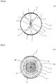
- Fig. 3 is a schematic diagram showing a cross-section in which the cells of the embodiment of the honeycomb structure of the present invention are orthogonal to the extending direction.
- Fig. 4 is a schematic diagram showing a cross-section in which the cells of the embodiment of the honeycomb structure of the present invention are orthogonal to the extending direction. Further, in Figs. 3 and 4 , the partition wall is omitted.
- each of the pair of electrodes 6 and 6 of the honeycomb structure 100 of the embodiment is formed in a band shape extending in the extending direction of the cell 2 of the honeycomb structure body 4. Then, in a cross-section orthogonal to the extending direction of the cell 2, one electrode 6 of the pair of electrodes 6 and 6 is disposed at the opposite side to the other electrode 6 of the pair of electrodes 6 and 6 with the center of the honeycomb structure body 4 interposed therebetween.
- a deviation in the temperature distribution of the honeycomb structure body 4 can be suppressed when a voltage is applied across the pair of electrodes 6 and 6. Further, the temperature of the center part 21 may be different from the temperature of the outer circumferential part 22.
- a "deviation in the temperature distribution of the honeycomb structure body 4" indicates a state where a temperature is locally high or low.
- the open frontal area of the center part 21 is 0.70 to 0.95 times the open frontal area of the outer circumferential part 22. For that reason, the electric resistivity of the center part 21 becomes lower than the electric resistivity of the outer circumferential part 22.
- a temperature can be raised to a necessary temperature up to the center part 21 in a short time when a voltage is applied to the honeycomb structure 100 to purify the exhaust gas. Then, the exhaust gas can be treated effectively at the center part 21 through which more exhaust gas flows compared to the outer circumferential part 22.
- the heat quantity required for the temperature of the center part to be raised to a necessary temperature can be decreased.
- one electrode 6 of the pair of electrodes 6 and 6 is disposed at the opposite side to the other electrode 6 of the pair of electrodes 6 and 6 with the center O of the honeycomb structure body 4 interposed therebetween in a cross-section orthogonal to the extending direction of the cell 2" means below.
- a “line connecting the center point of one electrode 6 (a center point in the "circumferential direction of the honeycomb structure body 4") to the center O of the honeycomb structure body 4" is denoted as a first line x.
- a “line connecting a center point of the other electrode 6 (a center point in the "circumferential direction of the honeycomb structure body 4") to the center O of the honeycomb structure body 4" is denoted as a second line y.
- the pair of electrodes 6 and 6 are disposed in the honeycomb structure body 4 so as to have a positional relation in which an angle ⁇ formed by the first line x and the second line y (an angle having a center as the "center O" (see Fig. 4 )) is in the range of 170° to 190°.
- a “center angle ⁇ of the electrode 6" is an angle formed by two lines connecting both end portions of the electrode 6 to the center O of the honeycomb structure body 4 in a cross-section orthogonal to the extending direction of the cells as shown in Fig. 4 .
- the "center angle ⁇ of the electrode 6" can be also mentioned as below.
- a "line connecting one end portion of the electrode 6 to the center O” is denoted as a third line z.
- a “line connecting the other end portion of the same electrode 6 to the center O” is denoted as a fourth line w.
- the “center angle ⁇ of the electrode 6" is an internal angle of the portion of the center O of the shape (for example, a fan shape) formed by the "electrode 6", the third line z, and the fourth line w in a cross-section orthogonal to the extending direction of the cells.
- the open frontal area of the center part 21 is 0.70 to 0.95 times the open frontal area of the outer circumferential part 22 as described above. Then, the open frontal area of the center part 21 is preferably 0.75 to 0.90 times and more preferably 0.80 to 0.85 times the open frontal area of the outer circumferential part 22.
- the open frontal area of the center part 21 is smaller than 0.70 times the open frontal area of the outer circumferential part 22, the pressure loss of the center part 21 becomes large and hence the exhaust gas does not easily flow.
- the open frontal area of the center part 21 is preferably 50 to 80%, more preferably 55 to 75%, and particularly preferably 60 to 70%. When the open frontal area is smaller than 50%, pressure loss often becomes large.
- the open frontal area of the outer circumferential part 22 is preferably 55 to 85%, more preferably 60 to 80%, and particularly preferably 65 to 75%.
- the open frontal area is smaller than 55%, it is often difficult for the open frontal area of the outer circumferential part 22 to be larger than the open frontal area of the center part 21.
- the open frontal area is larger than 85%, the strength of the honeycomb structure 100 is often degraded.
- the thickness of the partition wall of the center part 21 be thicker than the thickness of the partition wall of the outer circumferential part 22 so that the open frontal area of the center part 21 becomes smaller than (0.70 to 0.95 times) the open frontal area of the outer circumferential part 22.
- the thickness of the partition wall 1 of the center part 21 is preferably 1.0 to 2.0 times, more preferably 1.2 to 1.8 times, and particularly preferably 1.4 to 1.7 times the thickness of the partition wall 1 of the outer circumferential part 22.
- the thickness is smaller than 1.0 times the thickness of the partition wall 1 of the outer circumferential part 22, it is often difficult for the temperature rising speed of the center part 21 at the time of application of the voltage to be improved.
- the thickness is larger than 2.0 times the thickness of the partition wall 1 of the outer circumferential part 22, the pressure loss of the center part 21 often becomes so large that it is difficult for the exhaust gas to flow.
- the cell density of the center part 21 be larger than the cell density of the outer circumferential part 22 so that the open frontal area of the center part 21 becomes smaller than (0.70 to 0.95 times) the open frontal area of the outer circumferential part 22.
- the cell density of the center part 21 is preferably 1.0 to 1.5 times, more preferably 1.0 to 1.4 times, and particularly preferably 1.05 to 1.3 times the cell density of the outer circumferential part 22.
- the cell density of the center part 21 is smaller than 1.0 times the cell density of the outer circumferential part 22, it is often difficult for the temperature rising speed of the center part 21 at the time of application of the voltage to be improved.
- the pressure loss of the center part 21 often becomes so large that it is often difficult for the exhaust gas to flow.
- a rounded portion 14 is formed in an intersection point portion 13 of the partition wall 1 of the center part in a cross-section orthogonal to the extending direction of the cells.
- the rounded portion 14 is a portion which is formed thickly so that the surface of the intersection point portion 13 is formed in an "inward recessed circular arc shape".
- the surface of the partition wall 1 of the intersection point portion 13 of the partition wall 1 is smoothly connected in a circular arc shape by the rounded portion 14.
- a corner in the cross-sectional shape of the cell 2 is formed in a circular arc shape instead of an apex.
- Fig. 6 is a schematic diagram showing a cross-section orthogonal to the extending direction of the cells in the honeycomb structure of the embodiment.
- the open frontal area of the center part 21 which is smaller than (0.70 to 0.95 times) the open frontal area of the outer circumferential part 22 is preferably realized by the combination of the above-mentioned requirements for the partition wall thickness, the cell density, and the thickness of the intersection point portion of the partition wall.
- the open frontal area of an intermediate part 25 defined as an area between the center part 21 and the outer circumferential part 22 of the honeycomb structure body 4 be equal to or larger than the open frontal area of the center part 21 and equal to or smaller than the open frontal area of the outer circumferential part 22.
- the open frontal area of the intermediate part 25 is a value smaller than the open frontal area of the center part 21, much current often flows to the intermediate part 25 so that the temperature rising speed of the center part 21 decreases.
- the open frontal area of the intermediate part 25 is a value larger than the open frontal area of the outer circumferential part 22, the thermal shock resistance is often degraded.
- the thickness of the partition wall 1 of the center part 21 is preferably 100 to 310 ⁇ m, more preferably 130 to 250 ⁇ m, and particularly preferably 150 to 230 ⁇ m.
- the thickness of the partition wall 1 is in such a range, it is possible to suppress an excessive increase in pressure loss when the exhaust gas flows to the honeycomb structure 100 even when a catalyst is loaded on the honeycomb structure as a catalyst carrier.
- the thickness of the partition wall 1 is smaller than 100 ⁇ m, the strength of the honeycomb structure is often degraded.
- the thickness of the partition wall 1 is thicker than 310 ⁇ m, the pressure loss often increases when the exhaust gas flows to the honeycomb structure 100 where the honeycomb structure is used as the catalyst carrier to load a catalyst thereon.
- the entire honeycomb structure body 4 be formed of the same material.
- a material forming the honeycomb structure body 4 is different in accordance with the place (portion) of the honeycomb structure body 4, an operation or a process for changing the material is needed.
- the honeycomb structure 100 can be obtained by extruding a molding raw material prepared substantially uniformly to form a honeycomb formed body and firing the honeycomb formed body without changing the material thereof. For that reason, the honeycomb structure 100 is manufactured easily.
- the temperature of the center part 21 can be raised fast when a voltage is applied thereto. Further, in the honeycomb structure 100 of the embodiment, it is preferable that the electric resistivity of the material forming the center part 21 be equal to the electric resistivity of the material forming the outer circumferential part 22. Accordingly, an operation or a process of changing the material is not needed when the honeycomb structure 100 is manufactured.
- the cell density of the center part 21 is preferably 60 to 125 cells/cm 2 , more preferably 75 to 115 cells/cm 2 , and further preferably 85 to 110 cells/cm 2 .
- the cell density is in such a range, catalyst purifying performance can be improved while the pressure loss generated by the flow of the exhaust gas is small.
- the cell density is lower than 60 cells/cm 2 , a catalyst loading area often decreases.
- the pressure loss generated by the flow of the exhaust gas is often large when the honeycomb structure 100 is used as the catalyst carrier to load a catalyst thereon.
- the outer circumferential shape of the honeycomb structure body 4 (the outer circumferential shape of the outer circumferential part 22), the outer circumferential shape of the center part 21, and the inner circumferential shape of the outer circumferential part 22 be similar to one another.
- the outer circumferential shape of the honeycomb structure body 4 is circular
- the outer circumferential shape of the center part 21 and the inner circumferential shape of the outer circumferential part 22 be also circular.
- a center side area including the center part 21 is denoted as a center side area 23 and an outer circumference side area including the outer circumferential part 22 is denoted as an outer circumference side area 24.
- the open frontal area of the center side area 23 be equal to the open frontal area of the center part 21 and the open frontal area of the outer circumference side area 24 be equal to the open frontal area of the outer circumferential part 22.
- the center side area 23 having the "same open frontal area as the open frontal area of the center part 21" and the outer circumference side area 24 having the “same open frontal area as the open frontal area of the outer circumferential part 22" are formed in such a manner that the center side area 23 and the outer circumference side area 24 contact each other as shown in Figs. 1 to 3 .
- the configuration in which the center side area 23 and the outer circumference side area 24 contact each other means that a cross-section orthogonal to the extending direction of the cells of the honeycomb structure body is divided into two areas of the center side area 23 located at the center side and the outer circumference side area 24 located at the outer circumference side.
- an intermediate area 26 as a middle area having an intermediate open frontal area between the open frontal area of the center part 21 and the open frontal area of the outer circumferential part 22 may be formed between the center side area 23 having the "same open frontal area as the open frontal area of the center part 21" and the outer circumference side area 24 having the "same open frontal area as the open frontal area of the outer circumferential part 22" (see Fig. 5 ).
- the open frontal area of the intermediate part 25 may be uniform within the intermediate part 25, but may be changed stepwise from a portion contacting the center part 21 toward a portion contacting the outer circumferential part 22. Further, the open frontal area of the center side area 23 may be changed stepwise or continuously. Further, the open frontal area of the outer circumference side area 24 may be also changed stepwise and continuously. In addition, both open frontal areas of the center side area 23 and the outer circumference side area 24 may be changed continuously or stepwise or only one of them may be changed continuously or stepwise. In addition, the open frontal area of the center part 21 may be uniform or changed.
- Fig. 5 is a schematic diagram showing a cross-section orthogonal to the extending direction of the cells in the other embodiment of the honeycomb structure of the present invention (a honeycomb structure 200). In Fig. 5 , the partition wall is not shown in the drawings.
- the thermal stress in the vicinity of the electrode becomes large in the electric heating type honeycomb structure (the honeycomb structure body generating heat by energization) in which the band-shaped electrode is provided in the side surface of the honeycomb structure body. Accordingly, there is still room for improvement in thermal shock resistance.
- the open frontal area of the center part 21 of the honeycomb structure 100 of the embodiment is 0.70 to 0.95 times the open frontal area of the outer circumferential part 22 as described above, the Young's modulus of the outer circumferential part 22 becomes low and hence an effect of decreasing the thermal stress in the vicinity of the electrode 6 is obtained. In this way, since the Young's modulus of the outer circumferential part 22 in the honeycomb structure 100 of the embodiment is low and the thermal stress in the vicinity of the electrode 6 decreases, thermal shock resistance is high.
- the honeycomb structure body 4 and the electrode 6 be made of a material containing silicon carbide.
- a material containing silicon-silicon carbide composite material or silicon carbide as a main element can be exemplified.
- a material containing a silicon-silicon carbide composite material as a main element is more preferable.
- a material forming the honeycomb structure body 4 and the electrode 6 contains 95 mass% or more of a silicon-silicon carbide composite material.
- a case in which a "material is a silicon-silicon carbide composite material” means a case in which a "silicon-silicon carbide composite material" is contained by 95 mass% or more.
- the "main element” means an element contained by 90 mass% or more with respect to the entire element.
- the silicon-silicon carbide composite material is a material in which silicon carbide particles are bound by metallic silicon. It is preferable that the silicon-silicon carbide composite material be porous due to "silicon carbide particles bound by metallic silicon so that air holes are formed between the silicon carbide particles".
- the electric resistivity of the honeycomb structure body 4 can be 1 to 200 Qcm.
- the electric resistivity of the honeycomb structure body 4 is a value at 400°C.
- the element of the electrode 6 is similar or substantially similar to the element of the honeycomb structure body 4 and hence the thermal expansion coefficients of the electrode 6 and the honeycomb structure body 4 are equal or substantially equal to each other.
- the bonding strength between the electrode 6 and the honeycomb structure body 4 also becomes high. For that reason, even when a thermal stress is applied to the honeycomb structure 100, it is possible to prevent the electrode 6 from being peeled off the honeycomb structure body 4 or to prevent the bonded portion between the electrode 6 and the honeycomb structure body 4 from being broken.
- the content of metallic silicon in the silicon-silicon carbide composite material is preferably 10 to 50 mass% and more preferably 20 to 40 mass%.
- the electric resistivity of the honeycomb structure body 4 is often too high.
- the electric resistivity of the honeycomb structure body 4 is often too low.
- the pair of electrodes 6 and 6 are disposed on the side surface 5 of the honeycomb structure body 4.
- the honeycomb structure 100 of the embodiment generates heat when a voltage is applied across the pair of electrodes 6 and 6.
- the application voltage is preferably 12 to 900 V and more preferably 64 to 600 V.
- a material forming the honeycomb structure body 4 in the honeycomb structure 100 of the embodiment is a "silicon-silicon carbide composite material"
- the average particle diameter of silicon carbide particles (aggregate) forming the honeycomb structure body 4 be 3 to 50 ⁇ m.
- the average particle diameter of silicon carbide particles (aggregate) forming the honeycomb structure body 4 be 3 to 40 ⁇ m.
- the electric resistivity of the honeycomb structure body 4 at 400°C can be 1 to 200 Qcm.
- the electric resistivity of the honeycomb structure body 4 often becomes large.
- the electric resistivity of the honeycomb structure body 4 often becomes small.
- the average particle diameter of silicon carbide particles is larger than 50 ⁇ m, an extruding die is blocked by a molding raw material when the honeycomb formed body is extruded.
- the average particle diameter of silicon carbide particles is a value measured by a laser diffraction method.
- the porosity of the partition wall 1 of the honeycomb structure body 4 is preferably 35 to 60% and more preferably 35 to 45%. When the porosity is smaller than 35%, deformation during firing often becomes large. When the porosity exceeds 60%, the strength of the honeycomb structure is often degraded.
- the porosity is a value measured by a mercury porosimeter.
- the average pore diameter of the partition wall 1 of the honeycomb structure body 4 be preferably 2 to 15 ⁇ m and more preferably 4 to 8 ⁇ m.
- the average pore diameter is smaller than 2 ⁇ m, an electric resistivity often becomes large too much.
- the average pore diameter is larger than 15 ⁇ m, the electric resistivity often becomes small too much.
- the average pore diameter is a value measured by a mercury porosimeter.
- the shape of the honeycomb structure 100 of the embodiment is not particularly limited, but can be formed in a shape, for example, a pillar shape (columnar shape) in which a bottom face is circular, a pillar shape in which a bottom face is oval, or a pillar shape in which a bottom face is polygonal (a square, a pentagon, a hexagon, a heptagon, an octagon, or the like).
- the bottom face area is preferably 2000 to 20000 mm 2 and more preferably 4000 to 10000 mm 2 .
- the center axis length of the honeycomb structure 100 is preferably 50 to 200 mm and more preferably 75 to 150 mm.
- the diameter of the end face of the honeycomb structure body 4 is preferably 3 times or less, more preferably 0.5 to 2.5 times, and particularly preferably 0.8 to 2.0 times the length in the extending direction of the cell 2 of the honeycomb structure body 4. When the diameter of the end face of the honeycomb structure body 4 exceeds 3 times the length in the extending direction of the cell 2 of the honeycomb structure body 4, the honeycomb volume becomes small and hence a catalyst of an amount capable of exhibiting sufficient exhaust gas purifying performance cannot be loaded.
- the thickness of the circumferential wall 3 forming the outer circumference of the honeycomb structure body 4 of the honeycomb structure 100 of the embodiment be 0.1 to 2 mm.
- the thickness is smaller than 0.1 mm, the strength of the honeycomb structure 100 is often degraded.
- the thickness is larger than 2 mm, the area of the partition wall loading a catalyst often becomes small.
- the shape of the cell 2 be a square, a hexagon, an octagon, or a combination of theses. Since the cell shape is formed in this way, the pressure loss generated by the flow of the exhaust gas in the honeycomb structure 100 becomes small and hence the catalyst purifying performance is excellent.
- each of the pair of electrodes 6 and 6 is formed in a "band shape" extending in the extending direction of the cell 2 of the honeycomb structure body 4. Then, in a cross-section orthogonal to the extending direction of the cell 2, one electrode 6 of the pair of electrodes 6 and 6 is disposed at the opposite side to the other electrode 6 of the pair of electrodes 6 and 6 with the center O of the honeycomb structure body 4 interposed therebetween.
- the electrode 6 is formed in a band shape, the longitudinal direction of the electrode 6 is the extending direction of the cell 2 of the honeycomb structure body 4, and the pair of electrodes 6 and 6 are disposed at the opposite sides with the center O of the honeycomb structure body 4 interposed therebetween. For that reason, when a voltage is applied across the pair of electrodes 6 and 6, a deviation in the current flowing to each of the center part 21 and the outer circumferential part 22 can be suppressed and hence a deviation in the heating degree of each of the center part 21 and the outer circumferential part 22 can be suppressed.
- 0.5 times of the center angle ⁇ of each of the electrodes 6 and 6 is preferably 15 to 65°.
- the upper-limit value of the "angle ⁇ that is 0.5 times the center angle ⁇ " of the electrodes 6 and 6 is preferably 60° and more preferably 55°.
- the lower-limit value of the "angle ⁇ that is 0.5 times the center angle ⁇ " of the electrodes 6 and 6 is preferably 20° and more preferably 30°.
- the "angle ⁇ that is 0.5 times the center angle ⁇ " of one electrode 6 is preferably 0.8 to 1.2 times and more preferably 1.0 times the "angle ⁇ that is 0.5 times the center angle ⁇ " of the other electrode 6. Accordingly, when a voltage is applied across the pair of electrodes 6 and 6, a deviation in current flowing to each of the center part 21 and the outer circumferential part 22 can be suppressed and hence a deviation in heating degree of each of the center part 21 and the outer circumferential part 22 can be suppressed.
- the electric resistivity of the electrode 6 be lower than the electric resistivity of the center part 21 of the honeycomb structure body 4.
- the electric resistivity of the electrode 6 is more preferably 20% or less and particularly preferably 1 to 10% of the electric resistivity of the center part 21 of the honeycomb structure body 4.
- the electrode 6 more effectively serves as an electrode.
- the thickness of the electrode 6 is preferably 0.01 to 5 mm and more preferably 0.01 to 3 mm. With such a range, heat can be uniformly generated from each of the center part 21 and the outer circumferential part 22. When the thickness of the electrode 6 is smaller than 0.01 mm, electric resistance becomes high and hence heat cannot be generated uniformly. When the thickness is larger than 5 mm, a breakage occurs during canning.
- each of the pair of electrodes 6 and 6 extends in the extending direction of the cell 2 of the honeycomb structure body 4 and is formed in a band shape "between both end portions (between both end faces 11 and 12)".
- the pair of electrodes 6 and 6 is disposed across both end portions of the honeycomb structure body 4. Accordingly, when a voltage is applied across the pair of electrodes 6 and 6, a deviation in current flowing to each of the center part 21 and the outer circumferential part 22 can be more effectively suppressed.
- a case in which the "electrode 6 is disposed across both end portions of the honeycomb structure body 4" means below. That is, one end portion of the electrode 6 contacts one end portion (one end face) of the honeycomb structure body 4 and the other end portion of the electrode 6 contacts the other end portion (the other end face) of the honeycomb structure body 4.
- the electrode 6 is formed in a shape in which a planar rectangular member is curved along the columnar outer circumference.
- a shape in which the curved electrode 6 is deformed in a non-curved planar member will be referred to as the "planar shape" of the electrode 6.
- the "planar shape" of the electrode 6 shown in Figs. 1 to 4 becomes rectangular.
- the case of the "outer circumferential shape of the electrode” indicates the "outer circumferential shape in the planar shape of the electrode”.
- the outer circumferential shape of the band-shaped electrode 6 may be a shape in which a rectangular corner portion is formed in a curved line shape. With such a shape, the thermal shock resistance of the honeycomb structure 100 can be improved. Further, the outer circumferential shape of the band-shaped electrode 6 may be also formed in a shape in which the rectangular corner portion is chamfered in a linear shape. With such a shape, the thermal shock resistance of the honeycomb structure 100 can be improved.
- the electric resistivity of the electrode 6 is preferably 0.1 to 100 ⁇ cm and more preferably 0.1 to 50 Qcm.
- the pair of electrodes 6 and 6 effectively serve as electrodes in a pipe through which a high-temperature exhaust gas flows.
- the electric resistivity of the electrode 6 is smaller than 0.1 Qcm, the temperature of the honeycomb structure body 4 in the vicinity of both end portions of the electrode 6 often increases easily in a cross-section orthogonal to the extending direction of the cells.
- the electric resistivity of the electrode 6 is larger than 100 Qcm, a current does not flow easily thereto and hence the electrode is often unable to play a role of an electrode.
- the electric resistivity of the electrode 6 is a value at 400°C.
- the porosity of the electrode 6 is preferably 30 to 60% and more preferably 30 to 55%. When the porosity of the electrode 6 is in such a range, an appropriate electric resistivity can be obtained. When the porosity of the electrode 6 is lower than 30%, deformation often occurs during manufacturing. When the porosity of the electrode 6 is higher than 60%, the electric resistivity is often too high.
- the porosity is a value measured by a mercury porosimeter.
- the average pore diameter of the electrode 6 is preferably 5 to 45 ⁇ m and more preferably 7 to 40 ⁇ m. When the average pore diameter of the electrode 6 is in such a range, an appropriate electric resistivity can be obtained. When the average pore diameter of the electrode 6 is smaller than 5 ⁇ m, the electric resistivity is often too high. When the average pore diameter of the electrode 6 is larger than 45 ⁇ m, the strength of the electrode 6 is often weakened so that the electrode is easily broken.
- the average pore diameter is a value measured by a mercury porosimeter.
- the average particle diameter of silicon carbide particles contained in the electrode 6 is preferably 10 to 60 ⁇ m and more preferably 20 to 60 ⁇ m.
- the electric resistivity of the electrode 6 can be controlled in the range of 0.1 to 100 ⁇ cm.
- the average pore diameter of silicon carbide particles contained in the electrode 6 is smaller than 10 ⁇ m, the electric resistivity of the electrode 6 is often large too much.
- the average pore diameter of silicon carbide particles contained in the electrode 6 is larger than 60 ⁇ m, the strength of the electrode 6 is weakened so that the electrode is often broken easily.
- the average particle diameter of silicon carbide particles contained in the electrode 6 is a value measured by a laser diffraction method.
- the ratio of the mass of silicon contained in the electrode 6 with respect to the "sum of the mass of each of silicon carbide particle and silicon" contained in the electrode 6 be 20 to 40 mass%. Then, it is more preferable that the ratio of the mass of silicon with respect to the "sum of the mass of each of silicon carbide particle and silicon” contained in the electrode 6 be 25 to 35 mass%.
- the electric resistivity of the electrode 6 can be in the range of 0.1 to 100 ⁇ cm.
- the ratio of the mass of silicon with respect to the "sum of the mass of each of silicon carbide particle and silicon" contained in the electrode 6 is smaller than 20 mass%, the electric resistivity is often too large. Meanwhile, when the ratio is larger than 40 mass%, deformation often occurs during manufacturing.
- the isostatic strength of the honeycomb structure 100 of the embodiment is preferably 1 MPa or more and more preferably 3 MPa or more. It is preferable that the value of the isostatic strength become larger, but about 6 MPa becomes an upper limit in consideration of the material, the structure and the like of the honeycomb structure 100. When the isostatic strength is smaller than 1 MPa, there is often a concern of breakage when the honeycomb structure 100 is used as a catalyst carrier or the like.
- the isostatic strength is a value measured by applying a hydrostatic pressure under water.
- a method of manufacturing the honeycomb structure of the present invention is not particularly limited.
- the honeycomb structure of the present invention can be manufactured by adjusting the structure of a die used in, for example, extruding according to a known method.
- Silicon carbide (SiC) powder and metallic silicon (Si) powder were mixed at the mass ratio of 80 : 20 to thereby prepare a ceramic raw material. Then, hydroxypropylmethyl cellulose as a binder, water absorbable resin as a pore former, and water were added to the ceramic raw material to obtain a molding raw material. Then, the molding raw material was kneaded by a vacuum pugmill to form round pillar-shaped kneaded material. The content of the binder was 7 parts by mass when the sum of the silicon carbide (SiC) powder and the metallic silicon (Si) powder was set as 100 parts by mass.
- the content of the pore former was 3 parts by mass when the sum of the silicon carbide (SiC) powder and the metallic silicon (Si) powder was set as 100 parts by mass.
- the content of the water was 42 parts by mass when the sum of the silicon carbide (SiC) powder and the metallic silicon (Si) powder was set as 100 parts by mass.
- the average particle diameter of the silicon carbide powder was 20 ⁇ m and the average particle diameter of the metallic silicon powder was 6 ⁇ m. Further, the average particle diameter of the pore former was 20 ⁇ m.
- the average particle diameters of the silicon carbide, the metallic silicon, and the pore former were values measured by a laser diffraction method.
- the obtained round pillar-shaped kneaded material was extruded by an extruder to thereby obtain a honeycomb formed body having a shape similar to that of the honeycomb structure body 4 forming the honeycomb structure 100 shown in Fig. 1 .
- the obtained honeycomb formed body was formed in a shape including a portion with a "partition wall being formed thickly" and corresponding to the center side area 23 and a portion with a "partition wall being formed relatively thinly to the center side area 23" and corresponding to the outer circumference side area 24.
- the shape of the honeycomb formed body was adjusted by the shape of the die.
- the obtained honeycomb formed body was dried by induction heating, was dried by a hot air dryer for 2 hours at 120°C, and was cut by a predetermined amount at both end faces to thereby manufacture a honeycomb dried body.
- honeycomb dried body was degreased (calcinated), fired, and oxidized to thereby obtain a honeycomb fired body.
- the degreasing condition was set to 3 hours at 550°C.
- the firing condition was set to 2 hours at 1450°C in an argon atmosphere.
- the oxidizing condition was set to 1 hour at 1300°C.
- silicon carbide (SiC) powder and metallic silicon (Si) powder were mixed at the mass ratio of 60 : 40, and hydroxypropylmethyl cellulose as a binder, glycerin as a moisturizer, surfactant as a dispersing agent, and water were added to the mixed powder and mixed. The mixture was kneaded to thereby form an electrode forming raw material.
- the content of the binder was 0.5 part by mass when the sum of the silicon carbide (SiC) powder and the metallic silicon (Si) powder was set as 100 parts by mass
- the content of the glycerin was 10 parts by mass when the sum of the silicon carbide (SiC) powder and the metallic silicon (Si) powder was set as 100 parts by mass
- the content of the surfactant was 0.3 part by mass when the sum of the silicon carbide (SiC) powder and the metallic silicon (Si) powder was set as 100 parts by mass
- the content of the water was 42 parts by mass when the sum of the silicon carbide (SiC) powder and the metallic silicon (Si) powder was set as 100 parts by mass.
- the average particle diameter of the silicon carbide powder was 52 ⁇ m and the average particle diameter of the metallic silicon powder was 6 ⁇ m.
- the average particle diameters of the silicon carbide and the metallic silicon were values measured by a laser diffraction method. The kneading was performed by a vertical agitator.
- the electrode forming raw material was applied on the side surface of the honeycomb fired body in a band shape throughout both end faces of the honeycomb fired body so that a thickness of the applied electrode forming raw material was 0.15 mm and "0.5 times the center angle of the applied electrode forming raw material in a cross-section orthogonal to the extending direction of the cells was 50°".
- the electrode forming raw material was applied to two positions in the side surface of the honeycomb fired body. Then, one of two positions where the electrode forming raw material was applied in a cross-section orthogonal to the extending direction of the cells was disposed at the opposite side with the center of the honeycomb fired body interposed therebetween.
- the electrode forming raw material applied to the honeycomb fired body was dried to thereby obtain an unfired electrode attached honeycomb fired body.
- the drying temperature was set to 70°C.
- the unfired electrode attached honeycomb fired body was degreased (calcinated), fired, and oxidized to thereby obtain a honeycomb structure.
- the degreasing condition was set to 3 hours at 550°C in an oxidization atmosphere.
- the firing condition was set to 2 hours at 1450°C in an argon atmosphere.
- the oxidizing condition was set to 1 hour at 1300°C in an oxidization atmosphere.
- the average pore diameter (air hole diameter) of the partition wall of the obtained honeycomb structure was 8.6 ⁇ m and the porosity thereof was 45%.
- the average pore diameter and the porosity are values measured by a mercury porosimeter.
- the diameter of the circular honeycomb structure was 93 mm and the length of the honeycomb structure in the extending direction of the cells was 75 mm.
- the isostatic strength of the obtained honeycomb structure was 2.5 MPa.
- the isostatic strength is a breakage strength measured at a hydrostatic pressure in water.
- 0.5 times the center angle for each of the two electrodes of the honeycomb structure in a cross-section orthogonal to the extending direction of the cells was 50°. Further, all the thicknesses of two electrodes were 1.5 mm.
- the open frontal area of the center part was 0.95 times the open frontal area of the outer circumferential part.
- the honeycomb structure has a structure in which the center side area contacts the outer circumference side area in a cross-section orthogonal to the extending direction of the cells as in the honeycomb structure 100 shown in Fig. 1 .
- the thickness of the partition wall of the center side area of the honeycomb structure was 152 ⁇ m and the thickness of the partition wall of the outer circumference side area thereof was 127 ⁇ m.
- the cell density of the center side area of the honeycomb structure was 93.0 cells/cm 2 and the cell density of the outer circumference side area thereof was 93.0 cells/cm 2 .
- the cell shape was hexagonal in a cross-section orthogonal to the extending direction of the cells.
- the cell pitch was 1.11 mm.
- the cell pitch is a distance between the center parts in the thickness (partition wall thickness) direction of adjacent parallel partition walls (the partition walls forming two opposite side edges of the hexagon).
- the center part of the partition wall in the thickness direction is the center position of the partition wall in the thickness direction.
- the electric resistivity of the electrode was 1.3 ⁇ cm.
- the intersection point portion of the partition wall of the center part was provided with a rounded portion and the radius of the circular arc of the rounded portion was 0.3 mm.
- intersection point portion of the partition wall of the outer circumferential part was also provided with a rounded portion and the radius of the circular arc of the rounded portion was 0.3 mm. Further, the open frontal area of the center part was 71.8% and the open frontal area of the outer circumferential part was 75.8%.
- the "rib thickness ( ⁇ m)” indicates the thickness ( ⁇ m) of the partition wall.
- the "cell density (cells/cm3)” indicates the number of the cells per unit area (cm 3 ) in a cross-section orthogonal to the extending direction of the cells.
- the "intersection point R (mm)” indicates the radius of the circular arc of the rounded portion.
- the "open frontal area” indicates a value expressed as a percentage of a value which is obtained by dividing the area of the cell by the sum of the areas of the partition wall and the cell (the cell area sum/(the cell area sum + the partition wall area sum)) in a cross-section orthogonal to the extending direction of the cells.
- the open frontal area ratio indicates a value of the ratio of the open frontal area of the center part with respect to the open frontal area of the outer circumferential part (the open frontal area of the center part/the open frontal area of the outer circumferential part).
- the heating and cooling test for the honeycomb structure was performed by a "propane gas burner testing machine including a metallic casing receiving a honeycomb structure and a propane gas burner capable of supplying a heating gas into the metallic casing".
- the heating gas was a combustion gas for burning a propane gas by the gas burner (propane gas burner).
- the thermal shock resistance was evaluated by checking whether a crack was generated in the honeycomb structure by the heating and cooling test.
- the obtained honeycomb structure was received (canned) in the metallic casing of the propane gas burner testing machine.
- a gas (combustion gas) heated by the propane gas burner was supplied into the metallic casing so that the gas passed through the honeycomb structure.
- the temperature condition (inlet gas temperature condition) of the heating gas flowing into the metallic casing was set as below. First, the temperature was raised to 900°C in 5 minutes, was kept at 900°C for 10 minutes, was dropped to 100°C in 5 minutes, and was kept at 100°C for 10 minutes. A series of the temperature raising, cooling, and keeping operations will be referred to as a "temperature raising and dropping operation”. Subsequently, it was checked whether a crack was generated in the honeycomb structure. When a crack was not found, it was determined that the product passed the thermal shock resistance test. Meanwhile, when a crack was found, it was determined that the product did not pass the thermal shock resistance test.
- Example 1 A honeycomb structure was manufactured similarly to Example 1 except that the conditions were changed as shown in Table 1.
- Re-SiC means "recrystallization SiC” and is obtained by the recrystallization of silicon carbide.
- the "energization performance” and the “thermal shock resistance” of the honeycomb structure were measured. The result is shown in Table 1.
- honeycomb structure of the present invention can be appropriately used as an exhaust gas purifying catalyst carrier that purifies an exhaust gas of an automobile.
Landscapes
- Chemical & Material Sciences (AREA)
- Engineering & Computer Science (AREA)
- Ceramic Engineering (AREA)
- Chemical Kinetics & Catalysis (AREA)
- Materials Engineering (AREA)
- Organic Chemistry (AREA)
- Structural Engineering (AREA)
- Health & Medical Sciences (AREA)
- Combustion & Propulsion (AREA)
- Environmental & Geological Engineering (AREA)
- General Engineering & Computer Science (AREA)
- Toxicology (AREA)
- Mechanical Engineering (AREA)
- Biomedical Technology (AREA)
- Oil, Petroleum & Natural Gas (AREA)
- General Chemical & Material Sciences (AREA)
- Analytical Chemistry (AREA)
- Inorganic Chemistry (AREA)
- Manufacturing & Machinery (AREA)
- Catalysts (AREA)
- Exhaust Gas Treatment By Means Of Catalyst (AREA)
- Exhaust Gas After Treatment (AREA)
- Dispersion Chemistry (AREA)
Description
- The present invention relates to a honeycomb structure. More specifically, the present invention relates to a honeycomb structure that is a catalyst carrier and also serves as a heater when a voltage is applied thereto, and that is able to raise a temperature thereof to a necessary temperature up to a center part thereof in a short time when a voltage is applied thereto to purify an exhaust gas.
- Hitherto, a cordierite honeycomb structure having a catalyst loaded thereon has been used for the treatment of a harmful substance in an exhaust gas emitted from an automobile engine. Further, there is known a technology of using a honeycomb structure formed of a silicon carbide sintered body to purify an exhaust gas (for example, see Patent Document 1).
- When the exhaust gas is treated by the catalyst loaded on the honeycomb structure, there is a need to raise the temperature of the catalyst to a predetermined temperature. However, since the catalyst temperature is low when an engine is started, there is a problem that the exhaust gas is not sufficiently purified.
- For that reason, a method of raising the temperature of the exhaust gas by a metallic heater (metallic carrier for an electrically heating type of catalyst device) provided at the upstream side of the honeycomb structure having the catalyst loaded thereon has been examined (for example, see Patent Document 2).
- Further, there is proposed usage of a ceramic honeycomb structure as a "heatable catalyst carrier" (for example, see Patent Document 3).
-
- [Patent Document 1] Japanese Patent No.
4136319 - [Patent Document 2]
JP-A-8-131840 - [Patent Document 3]
WO 2011/125815 - When the above-described heater mounted on an automobile is used, a power supply which is used in an electric system of the automobile and supplies, for example, a high voltage of 200 V is commonly used. However, since the metallic heater has low electric resistance, there is a problem that an excessive current flows to the metallic heater to damage a power supply circuit when such a high-voltage power supply is used.
- Meanwhile, since the honeycomb structure disclosed in
Patent Document 3 is formed of ceramic having a predetermined electric resistivity, heat is uniformly (without a deviation in temperature distribution) generated by energization, without damaging a power supply circuit. The honeycomb structure disclosed inPatent Document 3 is excellent as an electric heating type catalyst carrier. Meanwhile, there is still room for improvement in that the vicinity of the center part, in which the flow rate of the exhaust gas is large, needs to be efficiently heated in order to cause a current to uniformly flow in the entire honeycomb structure. More specifically, since the honeycomb structure disclosed inPatent Document 3 has a configuration in which an electrode is disposed on a side surface of a pillar-shaped honeycomb structure body, and thus the heat generation proceeds from an outer circumferential part to a center part at the time of energization, there is room for improvement in that the time necessary for "raising the temperature of the center part to a temperature necessary for ensuring purifying performance" needs to be shortened. - The present invention is made in view of the above-described circumstances and an object of the present invention is to provide a honeycomb structure that is a catalyst carrier and also serves as a heater when a voltage is applied thereto, and that is able to raise a temperature thereof to a necessary temperature up to a center part thereof in a short time when a voltage is applied thereto to purify an exhaust gas.
- In order to solve the above-described problems, the present invention provides the following honeycomb structure.
- [1] A honeycomb structure that carries a catalyst and serves as a heater when a voltage is applied thereto including: a pillar-shaped honeycomb structure body that includes a porous partition wall which defines and forms a plurality of cells formed as fluid flow passages and extending from a first end face as one end face to a second end face as the other end face, and that includes a circumferential wall located at an outer circumference of the honeycomb structure body; and a pair of electrodes which are disposed on a side surface of the honeycomb structure body, wherein an electric resistivity of the honeycomb structure body is 1 to 200 Ωcm, each of the pair of electrodes is formed in a band shape extending in an extending direction of the cells of the honeycomb structure body, in a cross-section orthogonal to the extending direction of the cells, one electrode of the pair of electrodes is disposed at the opposite side to the other electrode of the pair of electrodes with a center of the honeycomb structure body interposed therebetween, and an open frontal area of a center part is 0.70 to 0.95 times an open frontal area of an outer circumferential part, where the center part is defined as an area from a center of the honeycomb structure body to a position of 10% of a length from the center to the outer circumference in a direction toward the outer circumference in a cross-section orthogonal to the extending direction of the cells of the honeycomb structure body, and the outer circumferential part is defined as an area from the outer circumference to a position of 10% of a length from the outer circumference to the center in a direction toward the center in the cross-section.
- [2] The honeycomb structure according to [1], wherein an open frontal area of an intermediate part defined as an area between the center part and the outer circumferential part in the honeycomb structure body, is equal to or larger than the open frontal area of the center part and equal to or smaller than the open frontal area of the outer circumferential part.
- [3] The honeycomb structure according to [1] or [2], wherein a thickness of the partition wall of the center part is 1.0 to 2.0 times a thickness of the partition wall of the outer circumferential part.
- [4] The honeycomb structure according to any one of [1] to [3], wherein the honeycomb structure body and the electrode are made of a material containing silicon carbide.
- [5] The honeycomb structure according to any one of [1] to [4], wherein a cell density of the center part is 1.0 to 1.5 times a cell density of the outer circumferential part.
- [6] The honeycomb structure according to any one of [1] to [5], wherein the open frontal area of the center part is 0.75 to 0.90 times the open frontal area of the outer circumferential part.
- [7] The honeycomb structure according to [6], wherein the open frontal area of the center part is 0.80 to 0.85 times the open frontal area of the outer circumferential part.
- In the honeycomb structure of the present invention, the open frontal area of the center part is 0.70 to 0.95 times the open frontal area of the outer circumferential part. For that reason, the electric resistivity of the center part becomes lower than the electric resistivity of the outer circumferential part. Thus, when a voltage is applied to the honeycomb structure, a large current flows to the center part and hence the center part is heated faster than the related art. Accordingly, a temperature can be raised to a necessary temperature up to the center part in a short time when a voltage is applied to the honeycomb structure to purify the exhaust gas. Then, the exhaust gas can be treated effectively at the center part through which more exhaust gas flows compared to the outer circumferential part.
-
-
Fig. 1 is a perspective view schematically showing an embodiment of a honeycomb structure of the present invention. -
Fig. 2 is a schematic diagram showing a cross-section in which cells of the embodiment of the honeycomb structure of the present invention are parallel in an extending direction. -
Fig. 3 is a schematic diagram showing a cross-section in which the cells of the embodiment of the honeycomb structure of the present invention are orthogonal to the extending direction. -
Fig. 4 is a schematic diagram showing a cross-section in which the cells of the embodiment of the honeycomb structure of the present invention are orthogonal to the extending direction. -
Fig. 5 is a schematic diagram showing a cross-section in which cells of the other embodiment of the honeycomb structure of the present invention are orthogonal to the extending direction. -
Fig. 6 is a schematic diagram showing a cross-section in which the cells of the embodiment of the honeycomb structure of the present invention are orthogonal to the extending direction. - Next, a mode for carrying out the present invention will be described in detail with reference to the drawings. It should be understood that the present invention is not limited to embodiments below and various modifications and improvements are made appropriately on the basis of the general knowledge of the person skilled in the art without departing from the spirit of the present invention.
- An embodiment of a honeycomb structure of the present invention includes, as shown in
Figs. 1 to 4 , a pillar-shapedhoneycomb structure body 4 and a pair ofelectrodes side surface 5 of thehoneycomb structure body 4. Thehoneycomb structure body 4 includes aporous partition wall 1 which defines and forms a plurality ofcells 2 formed as fluid flow passages and "extending from afirst end face 11 as one end face to asecond end face 12 as the other end face" and acircumferential wall 3 which is located in anouter circumference 7. Then, the electric resistivity of thehoneycomb structure body 4 is 1 to 200 Qcm. Then, each of the pair ofelectrodes cell 2 of thehoneycomb structure body 4. Then, in a cross-section orthogonal to the extending direction of thecell 2, oneelectrode 6 of the pair ofelectrodes other electrode 6 of the pair ofelectrodes honeycomb structure body 4 interposed therebetween. Then, in a cross-section orthogonal to the extending direction of thecell 2 of thehoneycomb structure body 4, acenter part 21 is defined as an area from the center O to the "position of 10% of the length from the center O to theouter circumference 7 in a direction toward theouter circumference 7". In addition, in the cross-section, an outercircumferential part 22 is defined as an area from theouter circumference 7 to "the position of 10% of the length from theouter circumference 7 to the center O in a direction toward the center O". Here, an open frontal area of thecenter part 21 is 0.70 to 0.95 times an open frontal area of the outercircumferential part 22. Here, the "open frontal area" is a value in which a value obtained by dividing the area of the cell by the sum of the areas of the partition wall and the cell (the cell area sum/(the cell area sum + the partition wall area sum)) is expressed as a percentage in a cross-section orthogonal to the extending direction of thecell 2 of thehoneycomb structure body 4. That is, the "open frontal area" of each area can be mentioned as an average value of the "open frontal area" in the corresponding area.Fig. 1 is a perspective view schematically showing an embodiment of the honeycomb structure of the present invention (a honeycomb structure 100).Fig. 2 is a schematic diagram showing a cross-section in which the cells of the embodiment of the honeycomb structure of the present invention are parallel in the extending direction.Fig. 3 is a schematic diagram showing a cross-section in which the cells of the embodiment of the honeycomb structure of the present invention are orthogonal to the extending direction.Fig. 4 is a schematic diagram showing a cross-section in which the cells of the embodiment of the honeycomb structure of the present invention are orthogonal to the extending direction. Further, inFigs. 3 and4 , the partition wall is omitted. - In this way, a current does not flow excessively to the
honeycomb structure 100 of the embodiment even when a current flows from a high-voltage power supply thereto since the electric resistivity of thehoneycomb structure body 4 is 1 to 200 Qcm and hence the honeycomb structure can be appropriately used as a heater. Further, each of the pair ofelectrodes honeycomb structure 100 of the embodiment is formed in a band shape extending in the extending direction of thecell 2 of thehoneycomb structure body 4. Then, in a cross-section orthogonal to the extending direction of thecell 2, oneelectrode 6 of the pair ofelectrodes other electrode 6 of the pair ofelectrodes honeycomb structure body 4 interposed therebetween. For that reason, a deviation in the temperature distribution of thehoneycomb structure body 4 can be suppressed when a voltage is applied across the pair ofelectrodes center part 21 may be different from the temperature of the outercircumferential part 22. A "deviation in the temperature distribution of thehoneycomb structure body 4" indicates a state where a temperature is locally high or low. - Further, in the
honeycomb structure 100 of the embodiment, the open frontal area of thecenter part 21 is 0.70 to 0.95 times the open frontal area of the outercircumferential part 22. For that reason, the electric resistivity of thecenter part 21 becomes lower than the electric resistivity of the outercircumferential part 22. Thus, when a voltage is applied to thehoneycomb structure 100, more current flows to thecenter part 21 and hence thecenter part 21 is heated fast. Accordingly, a temperature can be raised to a necessary temperature up to thecenter part 21 in a short time when a voltage is applied to thehoneycomb structure 100 to purify the exhaust gas. Then, the exhaust gas can be treated effectively at thecenter part 21 through which more exhaust gas flows compared to the outercircumferential part 22. In addition, the heat quantity required for the temperature of the center part to be raised to a necessary temperature can be decreased. - Here, "one
electrode 6 of the pair ofelectrodes other electrode 6 of the pair ofelectrodes honeycomb structure body 4 interposed therebetween in a cross-section orthogonal to the extending direction of thecell 2" means below. First, in a cross-section orthogonal to the extending direction of thecell 2, a "line connecting the center point of one electrode 6 (a center point in the "circumferential direction of thehoneycomb structure body 4") to the center O of thehoneycomb structure body 4" is denoted as a first line x. Then, in a cross-section orthogonal to the extending direction of thecell 2, a "line connecting a center point of the other electrode 6 (a center point in the "circumferential direction of thehoneycomb structure body 4") to the center O of thehoneycomb structure body 4" is denoted as a second line y. Here, it means that the pair ofelectrodes honeycomb structure body 4 so as to have a positional relation in which an angle β formed by the first line x and the second line y (an angle having a center as the "center O" (seeFig. 4 )) is in the range of 170° to 190°. Further, a "center angle α of theelectrode 6" is an angle formed by two lines connecting both end portions of theelectrode 6 to the center O of thehoneycomb structure body 4 in a cross-section orthogonal to the extending direction of the cells as shown inFig. 4 . Further, the "center angle α of theelectrode 6" can be also mentioned as below. First, in a cross-section orthogonal to the extending direction of the cells, a "line connecting one end portion of theelectrode 6 to the center O" is denoted as a third line z. Then, in a cross-section orthogonal to the extending direction of the cells, a "line connecting the other end portion of thesame electrode 6 to the center O" is denoted as a fourth line w. Here, the "center angle α of theelectrode 6" is an internal angle of the portion of the center O of the shape (for example, a fan shape) formed by the "electrode 6", the third line z, and the fourth line w in a cross-section orthogonal to the extending direction of the cells. - In the
honeycomb structure 100 of the embodiment, the open frontal area of thecenter part 21 is 0.70 to 0.95 times the open frontal area of the outercircumferential part 22 as described above. Then, the open frontal area of thecenter part 21 is preferably 0.75 to 0.90 times and more preferably 0.80 to 0.85 times the open frontal area of the outercircumferential part 22. When the open frontal area of thecenter part 21 is smaller than 0.70 times the open frontal area of the outercircumferential part 22, the pressure loss of thecenter part 21 becomes large and hence the exhaust gas does not easily flow. When the open frontal area of thecenter part 21 is larger than 0.95 times the open frontal area of the outercircumferential part 22, a temperature cannot be raised to a necessary temperature up to thecenter part 21 in a short time when a voltage is applied to thehoneycomb structure 100 to purify the exhaust gas. The ratio of the open frontal areas of thecenter part 21 and the outercircumferential part 22 has been described above. Here, each of the open frontal areas of thecenter part 21 and the outercircumferential part 22 will be described below. The open frontal area of thecenter part 21 is preferably 50 to 80%, more preferably 55 to 75%, and particularly preferably 60 to 70%. When the open frontal area is smaller than 50%, pressure loss often becomes large. When the open frontal area is larger than 80%, it is often difficult for the open frontal area of thecenter part 21 to be smaller than the open frontal area of the outercircumferential part 22. The open frontal area of the outercircumferential part 22 is preferably 55 to 85%, more preferably 60 to 80%, and particularly preferably 65 to 75%. When the open frontal area is smaller than 55%, it is often difficult for the open frontal area of the outercircumferential part 22 to be larger than the open frontal area of thecenter part 21. When the open frontal area is larger than 85%, the strength of thehoneycomb structure 100 is often degraded. - In the
honeycomb structure 100 of the embodiment, it is preferable that the thickness of the partition wall of thecenter part 21 be thicker than the thickness of the partition wall of the outercircumferential part 22 so that the open frontal area of thecenter part 21 becomes smaller than (0.70 to 0.95 times) the open frontal area of the outercircumferential part 22. Here, the thickness of thepartition wall 1 of thecenter part 21 is preferably 1.0 to 2.0 times, more preferably 1.2 to 1.8 times, and particularly preferably 1.4 to 1.7 times the thickness of thepartition wall 1 of the outercircumferential part 22. When the thickness is smaller than 1.0 times the thickness of thepartition wall 1 of the outercircumferential part 22, it is often difficult for the temperature rising speed of thecenter part 21 at the time of application of the voltage to be improved. When the thickness is larger than 2.0 times the thickness of thepartition wall 1 of the outercircumferential part 22, the pressure loss of thecenter part 21 often becomes so large that it is difficult for the exhaust gas to flow. - Further, it is preferable that the cell density of the
center part 21 be larger than the cell density of the outercircumferential part 22 so that the open frontal area of thecenter part 21 becomes smaller than (0.70 to 0.95 times) the open frontal area of the outercircumferential part 22. Here, the cell density of thecenter part 21 is preferably 1.0 to 1.5 times, more preferably 1.0 to 1.4 times, and particularly preferably 1.05 to 1.3 times the cell density of the outercircumferential part 22. When the cell density of thecenter part 21 is smaller than 1.0 times the cell density of the outercircumferential part 22, it is often difficult for the temperature rising speed of thecenter part 21 at the time of application of the voltage to be improved. When the cell density of thecenter part 21 is larger than 1.5 times the cell density of the outercircumferential part 22, the pressure loss of thecenter part 21 often becomes so large that it is often difficult for the exhaust gas to flow. - As shown in
Fig. 6 , it is preferable to form thehoneycomb structure 100 of the embodiment so that arounded portion 14 is formed in anintersection point portion 13 of thepartition wall 1 of the center part in a cross-section orthogonal to the extending direction of the cells. The roundedportion 14 is a portion which is formed thickly so that the surface of theintersection point portion 13 is formed in an "inward recessed circular arc shape". The surface of thepartition wall 1 of theintersection point portion 13 of thepartition wall 1 is smoothly connected in a circular arc shape by the roundedportion 14. Further, when theintersection point portion 13 of thepartition wall 1 includes the roundedportion 14, a corner in the cross-sectional shape of thecell 2 is formed in a circular arc shape instead of an apex. When the roundedportion 14 is formed in theintersection point portion 13 of thepartition wall 1 of the center part in this way, the open frontal area of the center part can be decreased. Further, theintersection point portion 13 of thepartition wall 1 in both the center part and the outer circumferential part may be formed thickly, and theintersection point portion 13 of thepartition wall 1 in the center part may be thicker than theintersection point portion 13 of thepartition wall 1 in the outer circumferential part. The radius of the circular-arc of the roundedportion 14 is preferably 0.05 to 0.6 mm.Fig. 6 is a schematic diagram showing a cross-section orthogonal to the extending direction of the cells in the honeycomb structure of the embodiment. - Further, the open frontal area of the
center part 21 which is smaller than (0.70 to 0.95 times) the open frontal area of the outercircumferential part 22 is preferably realized by the combination of the above-mentioned requirements for the partition wall thickness, the cell density, and the thickness of the intersection point portion of the partition wall. - It is preferable that the open frontal area of an
intermediate part 25 defined as an area between thecenter part 21 and the outercircumferential part 22 of thehoneycomb structure body 4, be equal to or larger than the open frontal area of thecenter part 21 and equal to or smaller than the open frontal area of the outercircumferential part 22. When the open frontal area of theintermediate part 25 is a value smaller than the open frontal area of thecenter part 21, much current often flows to theintermediate part 25 so that the temperature rising speed of thecenter part 21 decreases. When the open frontal area of theintermediate part 25 is a value larger than the open frontal area of the outercircumferential part 22, the thermal shock resistance is often degraded. - In the
honeycomb structure 100 of the embodiment, the thickness of thepartition wall 1 of thecenter part 21 is preferably 100 to 310 µm, more preferably 130 to 250 µm, and particularly preferably 150 to 230 µm. When the thickness of thepartition wall 1 is in such a range, it is possible to suppress an excessive increase in pressure loss when the exhaust gas flows to thehoneycomb structure 100 even when a catalyst is loaded on the honeycomb structure as a catalyst carrier. When the thickness of thepartition wall 1 is smaller than 100 µm, the strength of the honeycomb structure is often degraded. When the thickness of thepartition wall 1 is thicker than 310 µm, the pressure loss often increases when the exhaust gas flows to thehoneycomb structure 100 where the honeycomb structure is used as the catalyst carrier to load a catalyst thereon. - In the
honeycomb structure 100 of the embodiment, it is preferable that the entirehoneycomb structure body 4 be formed of the same material. When a material forming thehoneycomb structure body 4 is different in accordance with the place (portion) of thehoneycomb structure body 4, an operation or a process for changing the material is needed. On the contrary, when the entirehoneycomb structure body 4 is formed of the same material, thehoneycomb structure 100 can be obtained by extruding a molding raw material prepared substantially uniformly to form a honeycomb formed body and firing the honeycomb formed body without changing the material thereof. For that reason, thehoneycomb structure 100 is manufactured easily. Even when the entirehoneycomb structure body 4 is formed of the same material in this way in thehoneycomb structure 100 of the embodiment, the temperature of thecenter part 21 can be raised fast when a voltage is applied thereto. Further, in thehoneycomb structure 100 of the embodiment, it is preferable that the electric resistivity of the material forming thecenter part 21 be equal to the electric resistivity of the material forming the outercircumferential part 22. Accordingly, an operation or a process of changing the material is not needed when thehoneycomb structure 100 is manufactured. - In the
honeycomb structure 100 of the embodiment, the cell density of thecenter part 21 is preferably 60 to 125 cells/cm2, more preferably 75 to 115 cells/cm2, and further preferably 85 to 110 cells/cm2. When the cell density is in such a range, catalyst purifying performance can be improved while the pressure loss generated by the flow of the exhaust gas is small. When the cell density is lower than 60 cells/cm2, a catalyst loading area often decreases. When the cell density is higher than 125 cells/cm2, the pressure loss generated by the flow of the exhaust gas is often large when thehoneycomb structure 100 is used as the catalyst carrier to load a catalyst thereon. - In a cross-section orthogonal to the extending direction of the cells of the
honeycomb structure 100 of the embodiment, it is preferable that the outer circumferential shape of the honeycomb structure body 4 (the outer circumferential shape of the outer circumferential part 22), the outer circumferential shape of thecenter part 21, and the inner circumferential shape of the outercircumferential part 22 be similar to one another. For example, as shown inFigs. 1 to 3 , when the outer circumferential shape of thehoneycomb structure body 4 is circular, it is preferable that the outer circumferential shape of thecenter part 21 and the inner circumferential shape of the outercircumferential part 22 be also circular. - In a cross-section orthogonal to the extending direction of the
cell 2 in thehoneycomb structure 100 of the embodiment, a center side area including thecenter part 21 is denoted as acenter side area 23 and an outer circumference side area including the outercircumferential part 22 is denoted as an outercircumference side area 24. Here, it is preferable that the open frontal area of thecenter side area 23 be equal to the open frontal area of thecenter part 21 and the open frontal area of the outercircumference side area 24 be equal to the open frontal area of the outercircumferential part 22. In addition, it is a preferable configuration in which thecenter side area 23 having the "same open frontal area as the open frontal area of thecenter part 21" and the outercircumference side area 24 having the "same open frontal area as the open frontal area of the outercircumferential part 22" are formed in such a manner that thecenter side area 23 and the outercircumference side area 24 contact each other as shown inFigs. 1 to 3 . The configuration in which thecenter side area 23 and the outercircumference side area 24 contact each other means that a cross-section orthogonal to the extending direction of the cells of the honeycomb structure body is divided into two areas of thecenter side area 23 located at the center side and the outercircumference side area 24 located at the outer circumference side. Further, anintermediate area 26 as a middle area having an intermediate open frontal area between the open frontal area of thecenter part 21 and the open frontal area of the outercircumferential part 22 may be formed between thecenter side area 23 having the "same open frontal area as the open frontal area of thecenter part 21" and the outercircumference side area 24 having the "same open frontal area as the open frontal area of the outercircumferential part 22" (seeFig. 5 ). Further, in a cross-section orthogonal to the extending direction of thecell 2 of thehoneycomb structure 100 of the embodiment, the open frontal area of theintermediate part 25 may be uniform within theintermediate part 25, but may be changed stepwise from a portion contacting thecenter part 21 toward a portion contacting the outercircumferential part 22. Further, the open frontal area of thecenter side area 23 may be changed stepwise or continuously. Further, the open frontal area of the outercircumference side area 24 may be also changed stepwise and continuously. In addition, both open frontal areas of thecenter side area 23 and the outercircumference side area 24 may be changed continuously or stepwise or only one of them may be changed continuously or stepwise. In addition, the open frontal area of thecenter part 21 may be uniform or changed. When the open frontal area is changed, the open frontal area may be changed stepwise or continuously. Further, the open frontal area of the outercircumferential part 22 may be also uniform or changed. When the open frontal area is changed, the open frontal area may be changed stepwise or continuously. In addition, both the open frontal areas of thecenter part 21 and the outercircumferential part 22 may be changed continuously or stepwise or only one of them may be changed continuously or stepwise. Further, the open frontal area of theintermediate part 25 may be changed continuously from a portion contacting thecenter part 21 toward a portion contacting the outercircumferential part 22.Fig. 5 is a schematic diagram showing a cross-section orthogonal to the extending direction of the cells in the other embodiment of the honeycomb structure of the present invention (a honeycomb structure 200). InFig. 5 , the partition wall is not shown in the drawings. - There is a tendency that the thermal stress in the vicinity of the electrode becomes large in the electric heating type honeycomb structure (the honeycomb structure body generating heat by energization) in which the band-shaped electrode is provided in the side surface of the honeycomb structure body. Accordingly, there is still room for improvement in thermal shock resistance. On the contrary, since the open frontal area of the
center part 21 of thehoneycomb structure 100 of the embodiment is 0.70 to 0.95 times the open frontal area of the outercircumferential part 22 as described above, the Young's modulus of the outercircumferential part 22 becomes low and hence an effect of decreasing the thermal stress in the vicinity of theelectrode 6 is obtained. In this way, since the Young's modulus of the outercircumferential part 22 in thehoneycomb structure 100 of the embodiment is low and the thermal stress in the vicinity of theelectrode 6 decreases, thermal shock resistance is high. - In the
honeycomb structure 100 of the embodiment, it is preferable that thehoneycomb structure body 4 and theelectrode 6 be made of a material containing silicon carbide. As the material containing silicon carbide, a material containing a silicon-silicon carbide composite material or silicon carbide as a main element can be exemplified. Among these, a material containing a silicon-silicon carbide composite material as a main element is more preferable. Then, it is particularly preferable that a material forming thehoneycomb structure body 4 and theelectrode 6 contains 95 mass% or more of a silicon-silicon carbide composite material. In the present specification, a case in which a "material is a silicon-silicon carbide composite material" means a case in which a "silicon-silicon carbide composite material" is contained by 95 mass% or more. Here, the "main element" means an element contained by 90 mass% or more with respect to the entire element. The silicon-silicon carbide composite material is a material in which silicon carbide particles are bound by metallic silicon. It is preferable that the silicon-silicon carbide composite material be porous due to "silicon carbide particles bound by metallic silicon so that air holes are formed between the silicon carbide particles". When such a material is used, the electric resistivity of thehoneycomb structure body 4 can be 1 to 200 Qcm. The electric resistivity of thehoneycomb structure body 4 is a value at 400°C. Further, when thehoneycomb structure body 4 and theelectrode 6 contain silicon carbide particles and silicon as main elements, the element of theelectrode 6 is similar or substantially similar to the element of thehoneycomb structure body 4 and hence the thermal expansion coefficients of theelectrode 6 and thehoneycomb structure body 4 are equal or substantially equal to each other. Further, since the materials are same or substantially same, the bonding strength between theelectrode 6 and thehoneycomb structure body 4 also becomes high. For that reason, even when a thermal stress is applied to thehoneycomb structure 100, it is possible to prevent theelectrode 6 from being peeled off thehoneycomb structure body 4 or to prevent the bonded portion between theelectrode 6 and thehoneycomb structure body 4 from being broken. - When the
honeycomb structure body 4 is formed of a silicon-silicon carbide composite material, the content of metallic silicon in the silicon-silicon carbide composite material is preferably 10 to 50 mass% and more preferably 20 to 40 mass%. When the content is smaller than 10 mass%, the electric resistivity of thehoneycomb structure body 4 is often too high. When the content is larger than 50 mass%, the electric resistivity of thehoneycomb structure body 4 is often too low. - In the
honeycomb structure 100 of the embodiment, as shown inFigs. 1 to 4 , the pair ofelectrodes side surface 5 of thehoneycomb structure body 4. Thehoneycomb structure 100 of the embodiment generates heat when a voltage is applied across the pair ofelectrodes - When a material forming the
honeycomb structure body 4 in thehoneycomb structure 100 of the embodiment is a "silicon-silicon carbide composite material", it is preferable that the average particle diameter of silicon carbide particles (aggregate) forming thehoneycomb structure body 4 be 3 to 50 µm. Then, it is more preferable that the average particle diameter of silicon carbide particles (aggregate) forming thehoneycomb structure body 4 be 3 to 40 µm. When the average particle diameter of silicon carbide particles forming thehoneycomb structure body 4 is in such a range, the electric resistivity of thehoneycomb structure body 4 at 400°C can be 1 to 200 Qcm. When the average particle diameter of silicon carbide particles is smaller than 3 µm, the electric resistivity of thehoneycomb structure body 4 often becomes large. When the average particle diameter of silicon carbide particles is larger than 50 µm, the electric resistivity of thehoneycomb structure body 4 often becomes small. In addition, when the average particle diameter of silicon carbide particles is larger than 50 µm, an extruding die is blocked by a molding raw material when the honeycomb formed body is extruded. The average particle diameter of silicon carbide particles is a value measured by a laser diffraction method. - The porosity of the
partition wall 1 of thehoneycomb structure body 4 is preferably 35 to 60% and more preferably 35 to 45%. When the porosity is smaller than 35%, deformation during firing often becomes large. When the porosity exceeds 60%, the strength of the honeycomb structure is often degraded. The porosity is a value measured by a mercury porosimeter. - It is preferable that the average pore diameter of the
partition wall 1 of thehoneycomb structure body 4 be preferably 2 to 15 µm and more preferably 4 to 8 µm. When the average pore diameter is smaller than 2 µm, an electric resistivity often becomes large too much. When the average pore diameter is larger than 15 µm, the electric resistivity often becomes small too much. The average pore diameter is a value measured by a mercury porosimeter. - The shape of the
honeycomb structure 100 of the embodiment (the shape of the honeycomb structure body 4) is not particularly limited, but can be formed in a shape, for example, a pillar shape (columnar shape) in which a bottom face is circular, a pillar shape in which a bottom face is oval, or a pillar shape in which a bottom face is polygonal (a square, a pentagon, a hexagon, a heptagon, an octagon, or the like). Further, as the size of the honeycomb structure 100 (the honeycomb structure body 4), the bottom face area is preferably 2000 to 20000 mm2 and more preferably 4000 to 10000 mm2. Further, the center axis length of the honeycomb structure 100 (the honeycomb structure body 4) is preferably 50 to 200 mm and more preferably 75 to 150 mm. Further, the diameter of the end face of thehoneycomb structure body 4 is preferably 3 times or less, more preferably 0.5 to 2.5 times, and particularly preferably 0.8 to 2.0 times the length in the extending direction of thecell 2 of thehoneycomb structure body 4. When the diameter of the end face of thehoneycomb structure body 4 exceeds 3 times the length in the extending direction of thecell 2 of thehoneycomb structure body 4, the honeycomb volume becomes small and hence a catalyst of an amount capable of exhibiting sufficient exhaust gas purifying performance cannot be loaded. - Further, it is preferable that the thickness of the
circumferential wall 3 forming the outer circumference of thehoneycomb structure body 4 of thehoneycomb structure 100 of the embodiment be 0.1 to 2 mm. When the thickness is smaller than 0.1 mm, the strength of thehoneycomb structure 100 is often degraded. When the thickness is larger than 2 mm, the area of the partition wall loading a catalyst often becomes small. - In a cross-section orthogonal to the extending direction of the
cell 2 of thehoneycomb structure 100 of the embodiment, it is preferable that the shape of thecell 2 be a square, a hexagon, an octagon, or a combination of theses. Since the cell shape is formed in this way, the pressure loss generated by the flow of the exhaust gas in thehoneycomb structure 100 becomes small and hence the catalyst purifying performance is excellent. - As shown in
Figs. 1 to 4 , in thehoneycomb structure 100 of the embodiment, each of the pair ofelectrodes cell 2 of thehoneycomb structure body 4. Then, in a cross-section orthogonal to the extending direction of thecell 2, oneelectrode 6 of the pair ofelectrodes other electrode 6 of the pair ofelectrodes honeycomb structure body 4 interposed therebetween. In this way, in thehoneycomb structure 100 of the embodiment, theelectrode 6 is formed in a band shape, the longitudinal direction of theelectrode 6 is the extending direction of thecell 2 of thehoneycomb structure body 4, and the pair ofelectrodes honeycomb structure body 4 interposed therebetween. For that reason, when a voltage is applied across the pair ofelectrodes center part 21 and the outercircumferential part 22 can be suppressed and hence a deviation in the heating degree of each of thecenter part 21 and the outercircumferential part 22 can be suppressed. - In addition, in a cross-section orthogonal to the extending direction of the
cell 2, 0.5 times of the center angle α of each of theelectrodes 6 and 6 (the angle θ that is 0.5 times the center angle α) is preferably 15 to 65°. In addition, in a cross-section orthogonal to the extending direction of thecell 2, the upper-limit value of the "angle θ that is 0.5 times the center angle α" of theelectrodes cell 2, the lower-limit value of the "angle θ that is 0.5 times the center angle α" of theelectrodes electrode 6 is preferably 0.8 to 1.2 times and more preferably 1.0 times the "angle θ that is 0.5 times the center angle α" of theother electrode 6. Accordingly, when a voltage is applied across the pair ofelectrodes center part 21 and the outercircumferential part 22 can be suppressed and hence a deviation in heating degree of each of thecenter part 21 and the outercircumferential part 22 can be suppressed. - In the
honeycomb structure 100 of the embodiment, it is preferable that the electric resistivity of theelectrode 6 be lower than the electric resistivity of thecenter part 21 of thehoneycomb structure body 4. In addition, the electric resistivity of theelectrode 6 is more preferably 20% or less and particularly preferably 1 to 10% of the electric resistivity of thecenter part 21 of thehoneycomb structure body 4. When the electric resistivity of theelectrode 6 is 20% or less of the electric resistivity of thecenter part 21 of thehoneycomb structure body 4, theelectrode 6 more effectively serves as an electrode. - The thickness of the
electrode 6 is preferably 0.01 to 5 mm and more preferably 0.01 to 3 mm. With such a range, heat can be uniformly generated from each of thecenter part 21 and the outercircumferential part 22. When the thickness of theelectrode 6 is smaller than 0.01 mm, electric resistance becomes high and hence heat cannot be generated uniformly. When the thickness is larger than 5 mm, a breakage occurs during canning. - As shown in
Figs. 1 and2 , in thehoneycomb structure 100 of the embodiment, each of the pair ofelectrodes cell 2 of thehoneycomb structure body 4 and is formed in a band shape "between both end portions (between both end faces 11 and 12)". In this way, in thehoneycomb structure 100 of the embodiment, the pair ofelectrodes honeycomb structure body 4. Accordingly, when a voltage is applied across the pair ofelectrodes center part 21 and the outercircumferential part 22 can be more effectively suppressed. Here, a case in which the "electrode 6 is disposed across both end portions of thehoneycomb structure body 4" means below. That is, one end portion of theelectrode 6 contacts one end portion (one end face) of thehoneycomb structure body 4 and the other end portion of theelectrode 6 contacts the other end portion (the other end face) of thehoneycomb structure body 4. - Meanwhile, a state in which at least one end portion of the
electrode 6 in the "extending direction of thecell 2 of thehoneycomb structure body 4" does not contact the end portion (end face) of thehoneycomb structure body 4 is also preferable. Accordingly, the thermal shock resistance of the honeycomb structure can be improved. - In the
honeycomb structure 100 of the embodiment, for example, as shown inFigs. 1 to 4 , theelectrode 6 is formed in a shape in which a planar rectangular member is curved along the columnar outer circumference. Here, a shape in which thecurved electrode 6 is deformed in a non-curved planar member will be referred to as the "planar shape" of theelectrode 6. The "planar shape" of theelectrode 6 shown inFigs. 1 to 4 becomes rectangular. Then, the case of the "outer circumferential shape of the electrode" indicates the "outer circumferential shape in the planar shape of the electrode". - In the
honeycomb structure 100 of the embodiment, the outer circumferential shape of the band-shapedelectrode 6 may be a shape in which a rectangular corner portion is formed in a curved line shape. With such a shape, the thermal shock resistance of thehoneycomb structure 100 can be improved. Further, the outer circumferential shape of the band-shapedelectrode 6 may be also formed in a shape in which the rectangular corner portion is chamfered in a linear shape. With such a shape, the thermal shock resistance of thehoneycomb structure 100 can be improved. - The electric resistivity of the
electrode 6 is preferably 0.1 to 100 Ωcm and more preferably 0.1 to 50 Qcm. When the electric resistivity of theelectrode 6 is in such a range, the pair ofelectrodes electrode 6 is smaller than 0.1 Qcm, the temperature of thehoneycomb structure body 4 in the vicinity of both end portions of theelectrode 6 often increases easily in a cross-section orthogonal to the extending direction of the cells. When the electric resistivity of theelectrode 6 is larger than 100 Qcm, a current does not flow easily thereto and hence the electrode is often unable to play a role of an electrode. The electric resistivity of theelectrode 6 is a value at 400°C. - The porosity of the
electrode 6 is preferably 30 to 60% and more preferably 30 to 55%. When the porosity of theelectrode 6 is in such a range, an appropriate electric resistivity can be obtained. When the porosity of theelectrode 6 is lower than 30%, deformation often occurs during manufacturing. When the porosity of theelectrode 6 is higher than 60%, the electric resistivity is often too high. The porosity is a value measured by a mercury porosimeter. - The average pore diameter of the
electrode 6 is preferably 5 to 45 µm and more preferably 7 to 40 µm. When the average pore diameter of theelectrode 6 is in such a range, an appropriate electric resistivity can be obtained. When the average pore diameter of theelectrode 6 is smaller than 5 µm, the electric resistivity is often too high. When the average pore diameter of theelectrode 6 is larger than 45 µm, the strength of theelectrode 6 is often weakened so that the electrode is easily broken. The average pore diameter is a value measured by a mercury porosimeter. - When the main element of the
electrode 6 is a "silicon-silicon carbide composite material", the average particle diameter of silicon carbide particles contained in theelectrode 6 is preferably 10 to 60 µm and more preferably 20 to 60 µm. When the average particle diameter of silicon carbide particles contained in theelectrode 6 is in such a range, the electric resistivity of theelectrode 6 can be controlled in the range of 0.1 to 100 Ωcm. When the average pore diameter of silicon carbide particles contained in theelectrode 6 is smaller than 10 µm, the electric resistivity of theelectrode 6 is often large too much. When the average pore diameter of silicon carbide particles contained in theelectrode 6 is larger than 60 µm, the strength of theelectrode 6 is weakened so that the electrode is often broken easily. The average particle diameter of silicon carbide particles contained in theelectrode 6 is a value measured by a laser diffraction method. - When the main element of the
electrode 6 is a "silicon-silicon carbide composite material", it is preferable that the ratio of the mass of silicon contained in theelectrode 6 with respect to the "sum of the mass of each of silicon carbide particle and silicon" contained in theelectrode 6 be 20 to 40 mass%. Then, it is more preferable that the ratio of the mass of silicon with respect to the "sum of the mass of each of silicon carbide particle and silicon" contained in theelectrode 6 be 25 to 35 mass%. When the ratio of the mass of silicon with respect to the "sum of the mass of each of silicon carbide particle and silicon" contained in theelectrode 6 is in such a range, the electric resistivity of theelectrode 6 can be in the range of 0.1 to 100 Ωcm. When the ratio of the mass of silicon with respect to the "sum of the mass of each of silicon carbide particle and silicon" contained in theelectrode 6 is smaller than 20 mass%, the electric resistivity is often too large. Meanwhile, when the ratio is larger than 40 mass%, deformation often occurs during manufacturing. - The isostatic strength of the
honeycomb structure 100 of the embodiment is preferably 1 MPa or more and more preferably 3 MPa or more. It is preferable that the value of the isostatic strength become larger, but about 6 MPa becomes an upper limit in consideration of the material, the structure and the like of thehoneycomb structure 100. When the isostatic strength is smaller than 1 MPa, there is often a concern of breakage when thehoneycomb structure 100 is used as a catalyst carrier or the like. The isostatic strength is a value measured by applying a hydrostatic pressure under water. - A method of manufacturing the honeycomb structure of the present invention is not particularly limited. The honeycomb structure of the present invention can be manufactured by adjusting the structure of a die used in, for example, extruding according to a known method.
- Hereinafter, the present invention will be described in more detail by examples, but the present invention is not limited to these examples.
- Silicon carbide (SiC) powder and metallic silicon (Si) powder were mixed at the mass ratio of 80 : 20 to thereby prepare a ceramic raw material. Then, hydroxypropylmethyl cellulose as a binder, water absorbable resin as a pore former, and water were added to the ceramic raw material to obtain a molding raw material. Then, the molding raw material was kneaded by a vacuum pugmill to form round pillar-shaped kneaded material. The content of the binder was 7 parts by mass when the sum of the silicon carbide (SiC) powder and the metallic silicon (Si) powder was set as 100 parts by mass. The content of the pore former was 3 parts by mass when the sum of the silicon carbide (SiC) powder and the metallic silicon (Si) powder was set as 100 parts by mass. The content of the water was 42 parts by mass when the sum of the silicon carbide (SiC) powder and the metallic silicon (Si) powder was set as 100 parts by mass. The average particle diameter of the silicon carbide powder was 20 µm and the average particle diameter of the metallic silicon powder was 6 µm. Further, the average particle diameter of the pore former was 20 µm. The average particle diameters of the silicon carbide, the metallic silicon, and the pore former were values measured by a laser diffraction method.
- The obtained round pillar-shaped kneaded material was extruded by an extruder to thereby obtain a honeycomb formed body having a shape similar to that of the
honeycomb structure body 4 forming thehoneycomb structure 100 shown inFig. 1 . The obtained honeycomb formed body was formed in a shape including a portion with a "partition wall being formed thickly" and corresponding to thecenter side area 23 and a portion with a "partition wall being formed relatively thinly to thecenter side area 23" and corresponding to the outercircumference side area 24. The shape of the honeycomb formed body was adjusted by the shape of the die. - The obtained honeycomb formed body was dried by induction heating, was dried by a hot air dryer for 2 hours at 120°C, and was cut by a predetermined amount at both end faces to thereby manufacture a honeycomb dried body.
- Subsequently, the honeycomb dried body was degreased (calcinated), fired, and oxidized to thereby obtain a honeycomb fired body. The degreasing condition was set to 3 hours at 550°C. The firing condition was set to 2 hours at 1450°C in an argon atmosphere. The oxidizing condition was set to 1 hour at 1300°C.
- Next, silicon carbide (SiC) powder and metallic silicon (Si) powder were mixed at the mass ratio of 60 : 40, and hydroxypropylmethyl cellulose as a binder, glycerin as a moisturizer, surfactant as a dispersing agent, and water were added to the mixed powder and mixed. The mixture was kneaded to thereby form an electrode forming raw material. The content of the binder was 0.5 part by mass when the sum of the silicon carbide (SiC) powder and the metallic silicon (Si) powder was set as 100 parts by mass, the content of the glycerin was 10 parts by mass when the sum of the silicon carbide (SiC) powder and the metallic silicon (Si) powder was set as 100 parts by mass, the content of the surfactant was 0.3 part by mass when the sum of the silicon carbide (SiC) powder and the metallic silicon (Si) powder was set as 100 parts by mass, and the content of the water was 42 parts by mass when the sum of the silicon carbide (SiC) powder and the metallic silicon (Si) powder was set as 100 parts by mass. The average particle diameter of the silicon carbide powder was 52 µm and the average particle diameter of the metallic silicon powder was 6 µm. The average particle diameters of the silicon carbide and the metallic silicon were values measured by a laser diffraction method. The kneading was performed by a vertical agitator.
- Next, the electrode forming raw material was applied on the side surface of the honeycomb fired body in a band shape throughout both end faces of the honeycomb fired body so that a thickness of the applied electrode forming raw material was 0.15 mm and "0.5 times the center angle of the applied electrode forming raw material in a cross-section orthogonal to the extending direction of the cells was 50°". The electrode forming raw material was applied to two positions in the side surface of the honeycomb fired body. Then, one of two positions where the electrode forming raw material was applied in a cross-section orthogonal to the extending direction of the cells was disposed at the opposite side with the center of the honeycomb fired body interposed therebetween.
- Next, the electrode forming raw material applied to the honeycomb fired body was dried to thereby obtain an unfired electrode attached honeycomb fired body. The drying temperature was set to 70°C.
- Subsequently, the unfired electrode attached honeycomb fired body was degreased (calcinated), fired, and oxidized to thereby obtain a honeycomb structure. The degreasing condition was set to 3 hours at 550°C in an oxidization atmosphere. The firing condition was set to 2 hours at 1450°C in an argon atmosphere. The oxidizing condition was set to 1 hour at 1300°C in an oxidization atmosphere.
- The average pore diameter (air hole diameter) of the partition wall of the obtained honeycomb structure was 8.6 µm and the porosity thereof was 45%. The average pore diameter and the porosity are values measured by a mercury porosimeter. Further, the diameter of the circular honeycomb structure was 93 mm and the length of the honeycomb structure in the extending direction of the cells was 75 mm. Further, the isostatic strength of the obtained honeycomb structure was 2.5 MPa. The isostatic strength is a breakage strength measured at a hydrostatic pressure in water. In addition, 0.5 times the center angle for each of the two electrodes of the honeycomb structure in a cross-section orthogonal to the extending direction of the cells was 50°. Further, all the thicknesses of two electrodes were 1.5 mm.
- Further, the open frontal area of the center part was 0.95 times the open frontal area of the outer circumferential part. Further, the honeycomb structure has a structure in which the center side area contacts the outer circumference side area in a cross-section orthogonal to the extending direction of the cells as in the
honeycomb structure 100 shown inFig. 1 . Further, the thickness of the partition wall of the center side area of the honeycomb structure was 152 µm and the thickness of the partition wall of the outer circumference side area thereof was 127 µm. Further, the cell density of the center side area of the honeycomb structure was 93.0 cells/cm2 and the cell density of the outer circumference side area thereof was 93.0 cells/cm2. Further, the cell shape was hexagonal in a cross-section orthogonal to the extending direction of the cells. The cell pitch was 1.11 mm. The cell pitch is a distance between the center parts in the thickness (partition wall thickness) direction of adjacent parallel partition walls (the partition walls forming two opposite side edges of the hexagon). Further, the center part of the partition wall in the thickness direction is the center position of the partition wall in the thickness direction. Further, the electric resistivity of the electrode was 1.3 Ωcm. The intersection point portion of the partition wall of the center part was provided with a rounded portion and the radius of the circular arc of the rounded portion was 0.3 mm. Further, the intersection point portion of the partition wall of the outer circumferential part was also provided with a rounded portion and the radius of the circular arc of the rounded portion was 0.3 mm. Further, the open frontal area of the center part was 71.8% and the open frontal area of the outer circumferential part was 75.8%. - With regard to the obtained honeycomb structure, the "energization performance" and the "thermal shock resistance" were measured according to the following methods. The result is shown in Table 1.
- In Table 1, the "rib thickness (µm)" indicates the thickness (µm) of the partition wall. Further, the "cell density (cells/cm3)" indicates the number of the cells per unit area (cm3) in a cross-section orthogonal to the extending direction of the cells. Further, the "intersection point R (mm)" indicates the radius of the circular arc of the rounded portion. Further, the "open frontal area" indicates a value expressed as a percentage of a value which is obtained by dividing the area of the cell by the sum of the areas of the partition wall and the cell (the cell area sum/(the cell area sum + the partition wall area sum)) in a cross-section orthogonal to the extending direction of the cells. Further, the open frontal area ratio indicates a value of the ratio of the open frontal area of the center part with respect to the open frontal area of the outer circumferential part (the open frontal area of the center part/the open frontal area of the outer circumferential part).
- An energization test was performed on the honeycomb structure at the electric power of 5 kW. Then, the temperature at the center of the honeycomb structure body was measured. An energization time was measured until the center temperature of the honeycomb structure body reached 300°C and a required heat quantity (kJ) was compared. The heat quantity was calculated by the equation of "heat quantity = input electric power (kW) × energization time (sec)".
- The heating and cooling test for the honeycomb structure was performed by a "propane gas burner testing machine including a metallic casing receiving a honeycomb structure and a propane gas burner capable of supplying a heating gas into the metallic casing". The heating gas was a combustion gas for burning a propane gas by the gas burner (propane gas burner). Then, the thermal shock resistance was evaluated by checking whether a crack was generated in the honeycomb structure by the heating and cooling test. Specifically, the obtained honeycomb structure was received (canned) in the metallic casing of the propane gas burner testing machine. Then, a gas (combustion gas) heated by the propane gas burner was supplied into the metallic casing so that the gas passed through the honeycomb structure. The temperature condition (inlet gas temperature condition) of the heating gas flowing into the metallic casing was set as below. First, the temperature was raised to 900°C in 5 minutes, was kept at 900°C for 10 minutes, was dropped to 100°C in 5 minutes, and was kept at 100°C for 10 minutes. A series of the temperature raising, cooling, and keeping operations will be referred to as a "temperature raising and dropping operation". Subsequently, it was checked whether a crack was generated in the honeycomb structure. When a crack was not found, it was determined that the product passed the thermal shock resistance test. Meanwhile, when a crack was found, it was determined that the product did not pass the thermal shock resistance test.
[Table 1] Honeycomb Structure Energization Performance Thermal Shock Resistance Material of Honeycomb Structure Body Center part Outer circumferential part Open Frontal Area Ratio Intermediate part Input Electric Power (kW) Time (second) until reaching 300°C of Center Temperature Required Heat Quantity (kJ) for reaching 300°C of Center Temperature Heating and Cooling Test Result Rib Thickness (mm) Cell Density (cells/cells/cm2) Intersection Point R (mm) Open Frontal Area (%) Rib Thickness (mm) Cell Density (cells/cells/cm2) Intersection Point R (mm) Open Frontal Area (%) Rib Thickness (mm) Cell Density (cells/cells/cm2) Intersection Point R (mm) Open Frontal Area (%) Comparative Example 1 Si-SiC 127 93.0 0.3 75.8 127 93.0 0.3 75.8 1.00 - - - - 5 40 200 Fail Example 1 Si-SiC 152 93.0 0.3 71.8 127 93.0 0.3 75.8 0.95 - - - - 5 37 185 Pass Example 2 Si-SiC 203 93.0 0.3 64.2 127 93.0 0.3 75.8 0.85 - - - - 5 34 170 Pass Example 3 Si-SiC 203 93.0 0.3 64.2 102 93.0 0.3 79.9 0.80 - - - - 5 33 165 Pass Example 4 Si-SiC 203 93.0 0.3 64.2 152 93.0 0.3 71.8 0.89 - - - - 5 36 180 Pass Example 5 Si-SiC 229 93.0 0.3 60.5 127 93.0 0.3 75.8 0.80 - - - - 5 33 165 Pass Example 6 Si-SiC 254 93.0 0.3 56.9 127 93.0 0.3 75.8 0.75 - - - - 5 37 185 Pass Comparative Example 2 Si-SiC 330 93.0 0.3 46.8 127 93.0 0.3 75.8 0.62 - - - - 5 43 215 Fail Example 7 Si-SiC 152 93.0 0.5 67.0 152 93.0 0.3 71.8 0.93 - - - - 5 37 185 Pass Example 8 Si-SiC 152 93.0 0.6 63.7 152 93.0 0 74.5 0.86 - - - - 5 35 175 Pass Example 9 Si-SiC 152 104.0 0.3 70.1 152 80.0 0.3 73.9 0.95 - - - - 5 36 180 Pass Example 10 Si-SiC 152 130.0 0.3 66.5 152 80.0 0.3 73.9 0.90 - - - - 5 37 185 Pass Example 11 Si-SiC 203 93.0 0.3 64.2 127 93.0 0.3 75.8 0.85 178 93.0 0.3 67.9 5 34 170 Pass Example 12 Re-SiC 203 93.0 0.3 64.2 127 93.0 0.3 75.8 0.85 - - - - 5 35 175 Pass - A honeycomb structure was manufactured similarly to Example 1 except that the conditions were changed as shown in Table 1. In Table 1, "Re-SiC" means "recrystallization SiC" and is obtained by the recrystallization of silicon carbide. Similarly to the case of Example 1, the "energization performance" and the "thermal shock resistance" of the honeycomb structure were measured. The result is shown in Table 1.
- From Table 1, in the honeycomb structures of Examples 1 to 12, it is understood that the temperature of the center part rises fast and the necessary heat quantity is small because the open frontal area of the center part is 0.70 to 0.95 times the open frontal area of the outer circumferential part. Further, in the honeycomb structures of Examples 1 to 12, it is understood that the thermal shock resistance is excellent because the open frontal area of the center part is 0.70 to 0.95 times the open frontal area of the outer circumferential part. Further, in the honeycomb structure of Example 10, it is acknowledged that the pressure loss increases when an exhaust gas passes through the honeycomb structure loading a catalyst thereon compared with the honeycomb structure of Example 9 because the cell density of the center part is high.
- The honeycomb structure of the present invention can be appropriately used as an exhaust gas purifying catalyst carrier that purifies an exhaust gas of an automobile.
- 1: partition wall, 2:cell, 3:circumferential wall, 4:honeycomb structure body, 5:side surface, 6:electrode, 7:outer circumference, 11:first end face, 12:second end face, 13: intersection point portion, 14:rounded portion, 21: center part, 22: outer circumferential part, 23: center side area, 24: outer circumference side area, 25:intermediate part, 26:intermediate area, 100, 200:honeycomb structure, O:center, α:center angle, β:angle, θ:angle of 0.5 times center angle, x:first line, y:second line, z:third line, w:fourth line
Claims (7)
- A honeycomb structure that carries a catalyst and serves as a heater when a voltage is applied thereto comprising:a pillar-shaped honeycomb structure body (4) that includes a porous partition wall (1) which defines and forms a plurality of cells (2) formed as fluid flow passages and extending from a first end face (11) as one end face to a second end face (12) as the other end face, and that includes a circumferential wall (3) located at an outer circumference (7) of the honeycomb structure body; anda pair of electrodes (6) which are disposed on a side surface of the honeycomb structure body, whereinan electric resistivity of the honeycomb structure body (4) is 1 to 200 Ωcm,each of the pair of electrodes (6) is formed in a band shape extending in an extending direction of the cells (2) of the honeycomb structure body (4),in a cross-section orthogonal to the extending direction of the cells (2), one electrode of the pair of electrodes (6) is disposed at the opposite side to the other electrode of the pair of electrodes (6) with a center (O) of the honeycomb structure body (4) interposed therebetween,
characterized in thatan open frontal area of a center part (21) is 0.70 to 0.95 times an open frontal area of an outer circumferential part (22), where the center part is defined as an area from a center (O) of the honeycomb structure body (4) to a position of 10% of a length from the center (O) to the outer circumference (7) in a direction toward the outer circumference (7) in a cross-section orthogonal to the extending direction of the cells (2) of the honeycomb structure body (4), and the outer circumferential part (22) is defined as an area from the outer circumference (7) to a position of 10% of a length from the outer circumference (7) to the center (O) in a direction toward the center (O) in the cross-section. - The honeycomb structure according to claim 1, wherein an open frontal area of an intermediate part (25) defined as an area between the center part (21) and the outer circumferential part (22) in the honeycomb structure body (4), is equal to or larger than the open frontal area of the center part (21) and equal to or smaller than the open frontal area of the outer circumferential part (22).
- The honeycomb structure according to claim 1 or 2, wherein a thickness of the partition wall (1) of the center part (21) is 1.0 to 2.0 times a thickness of the partition wall (1) of the outer circumferential part (22).
- The honeycomb structure according to any one of claims 1 to 3, wherein the honeycomb structure body (4) and the electrode (6) are made of a material containing silicon carbide.
- The honeycomb structure according to any one of claims 1 to 4, wherein a cell density of the center part (21) is 1.0 to 1.5 times a cell density of the outer circumferential part (22).
- The honeycomb structure according to any one of claims 1 to 5, wherein the open frontal area of the center part (21) is 0.75 to 0.90 times the open frontal area of the outer circumferential part (22).
- The honeycomb structure according to claim 6, wherein the open frontal area of the center part (21) is 0.80 to 0.85 times the open frontal area of the outer circumferential part (22).
Applications Claiming Priority (2)
| Application Number | Priority Date | Filing Date | Title |
|---|---|---|---|
| JP2014071857 | 2014-03-31 | ||
| PCT/JP2015/058170 WO2015151823A1 (en) | 2014-03-31 | 2015-03-19 | Honeycomb structure |
Publications (3)
| Publication Number | Publication Date |
|---|---|
| EP3127611A1 EP3127611A1 (en) | 2017-02-08 |
| EP3127611A4 EP3127611A4 (en) | 2017-11-15 |
| EP3127611B1 true EP3127611B1 (en) | 2018-12-26 |
Family
ID=54240154
Family Applications (1)
| Application Number | Title | Priority Date | Filing Date |
|---|---|---|---|
| EP15774243.8A Active EP3127611B1 (en) | 2014-03-31 | 2015-03-19 | Honeycomb structure |
Country Status (5)
| Country | Link |
|---|---|
| US (1) | US9993813B2 (en) |
| EP (1) | EP3127611B1 (en) |
| JP (1) | JP6438939B2 (en) |
| CN (1) | CN106029226B (en) |
| WO (1) | WO2015151823A1 (en) |
Families Citing this family (18)
| Publication number | Priority date | Publication date | Assignee | Title |
|---|---|---|---|---|
| JP6934702B2 (en) * | 2015-03-27 | 2021-09-15 | 株式会社デンソー | Exhaust gas purification filter |
| JP6625920B2 (en) * | 2016-03-25 | 2019-12-25 | トヨタ自動車株式会社 | Catalytic converter |
| JP6767235B2 (en) * | 2016-10-19 | 2020-10-14 | 日本碍子株式会社 | Sealed honeycomb structure |
| JP6829979B2 (en) * | 2016-10-19 | 2021-02-17 | 日本碍子株式会社 | Sealed honeycomb structure |
| JP6803275B2 (en) * | 2017-03-17 | 2020-12-23 | 日本碍子株式会社 | Honeycomb structure |
| JP6830018B2 (en) * | 2017-03-28 | 2021-02-17 | 日本碍子株式会社 | Honeycomb structure |
| JP6999470B2 (en) * | 2018-03-28 | 2022-01-18 | 日本碍子株式会社 | Honeycomb structure |
| JP6626524B2 (en) * | 2018-03-29 | 2019-12-25 | 日本碍子株式会社 | Electric heating type catalyst carrier |
| JP7058536B2 (en) * | 2018-03-29 | 2022-04-22 | 日本碍子株式会社 | Honeycomb structure |
| US10888856B2 (en) * | 2018-04-13 | 2021-01-12 | Ngk Insulators, Ltd. | Honeycomb structure |
| JP7034376B2 (en) * | 2019-03-22 | 2022-03-11 | 日本碍子株式会社 | Honeycomb structure and exhaust gas purification device |
| JP7165088B2 (en) * | 2019-03-28 | 2022-11-02 | 日本碍子株式会社 | honeycomb structure |
| US11215096B2 (en) | 2019-08-21 | 2022-01-04 | Corning Incorporated | Systems and methods for uniformly heating a honeycomb body |
| JP7422635B2 (en) * | 2020-09-23 | 2024-01-26 | 日本碍子株式会社 | Electrically heated carrier, exhaust gas purification device, and method for producing electrically heated carrier |
| CN114940619B (en) * | 2021-02-15 | 2024-06-18 | 日本碍子株式会社 | Method for manufacturing honeycomb structure and method for manufacturing electrically heated carrier |
| JP2022126503A (en) * | 2021-02-18 | 2022-08-30 | 日本碍子株式会社 | Method for producing honeycomb structure and method for producing electric heating type carrier |
| JP7305695B2 (en) * | 2021-03-26 | 2023-07-10 | 日本碍子株式会社 | Method for manufacturing columnar honeycomb fired body |
| JP2023145986A (en) * | 2022-03-29 | 2023-10-12 | 日本碍子株式会社 | honeycomb filter |
Family Cites Families (36)
| Publication number | Priority date | Publication date | Assignee | Title |
|---|---|---|---|---|
| US4505107A (en) * | 1981-10-26 | 1985-03-19 | Nippondenso Co., Ltd. | Exhaust gas cleaning apparatus |
| JP2931362B2 (en) * | 1990-04-12 | 1999-08-09 | 日本碍子株式会社 | Resistance control type heater and catalytic converter |
| US5266278A (en) * | 1990-07-06 | 1993-11-30 | Ngk Insulators, Ltd. | Honeycomb heater having integrally formed electrodes and/or integrally sintered electrodes and method of manufacturing such honeycomb heater |
| JP3001281B2 (en) * | 1991-03-06 | 2000-01-24 | 日本碍子株式会社 | Honeycomb monolith heater |
| US5259190A (en) * | 1991-08-01 | 1993-11-09 | Corning Incorporated | Heated cellular structures |
| US5651248A (en) * | 1994-08-29 | 1997-07-29 | Isuzu Ceramics Research Institute Co., Ltd. | Diesel particulate filter apparatus |
| JP3340865B2 (en) | 1994-11-16 | 2002-11-05 | 昭和飛行機工業株式会社 | Metal carrier for electric heating type catalytic device |
| JPH08273805A (en) * | 1995-03-30 | 1996-10-18 | Ngk Insulators Ltd | Current applicable heating honeycomb body |
| JP3345222B2 (en) * | 1995-07-21 | 2002-11-18 | 日本碍子株式会社 | Honeycomb body and honeycomb unit for energized heating |
| JPH09103684A (en) * | 1995-10-13 | 1997-04-22 | Ngk Insulators Ltd | Parallel heating type honeycomb heater |
| JP4455800B2 (en) * | 1999-11-19 | 2010-04-21 | 日本碍子株式会社 | Honeycomb structure |
| JP4136319B2 (en) | 2000-04-14 | 2008-08-20 | 日本碍子株式会社 | Honeycomb structure and manufacturing method thereof |
| JP4094823B2 (en) * | 2001-04-03 | 2008-06-04 | 日本碍子株式会社 | Honeycomb structure and assembly thereof |
| JP5052717B2 (en) * | 2001-05-02 | 2012-10-17 | 日本碍子株式会社 | Honeycomb structure, and honeycomb filter and converter system using the same |
| EP1415779B1 (en) * | 2001-07-13 | 2009-09-23 | Ngk Insulators, Ltd. | Honeycomb structural body, honeycomb filter, and method of manufacturing the structural body and the filter |
| JP4279497B2 (en) * | 2002-02-26 | 2009-06-17 | 日本碍子株式会社 | Honeycomb filter |
| JP4293753B2 (en) * | 2002-03-19 | 2009-07-08 | 日本碍子株式会社 | Honeycomb filter |
| JP2004154768A (en) * | 2002-10-15 | 2004-06-03 | Denso Corp | Exhaust gas purifying filter and method for manufacturing the same |
| US6946013B2 (en) * | 2002-10-28 | 2005-09-20 | Geo2 Technologies, Inc. | Ceramic exhaust filter |
| US7238217B2 (en) * | 2004-04-23 | 2007-07-03 | Corning Incorporated | Diesel engine exhaust filters |
| DE102006035053A1 (en) * | 2005-09-20 | 2007-03-22 | Robert Bosch Gmbh | Filter element and soot filter with geometrically similar channels |
| DE102007024563A1 (en) * | 2007-05-25 | 2008-11-27 | Emitec Gesellschaft Für Emissionstechnologie Mbh | Device comprising a large electrically heatable honeycomb body |
| CN102574746B (en) * | 2009-10-07 | 2014-04-16 | 日本碍子株式会社 | Honeycomb structure |
| JP4825309B2 (en) * | 2010-01-19 | 2011-11-30 | 住友化学株式会社 | Honeycomb structure |
| EP2540382B1 (en) * | 2010-02-26 | 2020-03-25 | NGK Insulators, Ltd. | Honeycomb structure |
| EP2554264B1 (en) * | 2010-03-31 | 2017-05-31 | NGK Insulators, Ltd. | Honeycomb structure |
| WO2011125815A1 (en) * | 2010-03-31 | 2011-10-13 | 日本碍子株式会社 | Honeycomb structure |
| EP2554265B1 (en) * | 2010-03-31 | 2017-07-26 | NGK Insulators, Ltd. | Honeycomb structure |
| JP5617764B2 (en) * | 2010-09-27 | 2014-11-05 | 株式会社デンソー | Honeycomb structure and electrically heated catalyst device |
| JP5691848B2 (en) * | 2010-09-27 | 2015-04-01 | 株式会社デンソー | Honeycomb structure and electrically heated catalyst device |
| JP5883299B2 (en) * | 2011-03-24 | 2016-03-09 | 日本碍子株式会社 | Heater for heating lubricating fluid |
| JP5872572B2 (en) | 2011-09-30 | 2016-03-01 | 日本碍子株式会社 | Honeycomb structure |
| JP5892911B2 (en) * | 2012-01-27 | 2016-03-23 | 株式会社デンソー | Honeycomb structure |
| JP5771541B2 (en) * | 2012-01-27 | 2015-09-02 | 株式会社デンソー | Honeycomb structure |
| WO2013146955A1 (en) * | 2012-03-30 | 2013-10-03 | 日本碍子株式会社 | Honeycomb structure |
| JP5708670B2 (en) * | 2013-01-18 | 2015-04-30 | 株式会社デンソー | Honeycomb structure |
-
2015
- 2015-03-19 WO PCT/JP2015/058170 patent/WO2015151823A1/en active Application Filing
- 2015-03-19 EP EP15774243.8A patent/EP3127611B1/en active Active
- 2015-03-19 CN CN201580009114.5A patent/CN106029226B/en active Active
- 2015-03-19 JP JP2016511526A patent/JP6438939B2/en active Active
-
2016
- 2016-08-10 US US15/232,976 patent/US9993813B2/en active Active
Non-Patent Citations (1)
| Title |
|---|
| None * |
Also Published As
| Publication number | Publication date |
|---|---|
| EP3127611A4 (en) | 2017-11-15 |
| CN106029226B (en) | 2018-12-28 |
| JP6438939B2 (en) | 2018-12-19 |
| US20160346776A1 (en) | 2016-12-01 |
| US9993813B2 (en) | 2018-06-12 |
| WO2015151823A1 (en) | 2015-10-08 |
| CN106029226A (en) | 2016-10-12 |
| EP3127611A1 (en) | 2017-02-08 |
| JPWO2015151823A1 (en) | 2017-04-13 |
Similar Documents
| Publication | Publication Date | Title |
|---|---|---|
| EP3127611B1 (en) | Honeycomb structure | |
| US9707515B2 (en) | Honeycomb structure | |
| US8803043B2 (en) | Honeycomb structure | |
| EP2784051B1 (en) | Honeycomb structure | |
| US8597585B2 (en) | Honeycomb structure | |
| EP2656902B1 (en) | Honeycomb structure | |
| EP2554265A1 (en) | Honeycomb structure | |
| EP2484446A1 (en) | Honeycomb structure | |
| EP2656900B1 (en) | Honeycomb structure | |
| US9228470B2 (en) | Honeycomb structure | |
| US20130270258A1 (en) | Honeycomb structure | |
| JP2015174011A (en) | honeycomb structure | |
| US9279356B2 (en) | Honeycomb structure and manufacturing method of the same | |
| EP3056274A1 (en) | Honeycomb structure | |
| EP2784047A2 (en) | Honeycomb structure | |
| US20190299200A1 (en) | Honeycomb structure |
Legal Events
| Date | Code | Title | Description |
|---|---|---|---|
| STAA | Information on the status of an ep patent application or granted ep patent |
Free format text: STATUS: THE INTERNATIONAL PUBLICATION HAS BEEN MADE |
|
| PUAI | Public reference made under article 153(3) epc to a published international application that has entered the european phase |
Free format text: ORIGINAL CODE: 0009012 |
|
| STAA | Information on the status of an ep patent application or granted ep patent |
Free format text: STATUS: REQUEST FOR EXAMINATION WAS MADE |
|
| 17P | Request for examination filed |
Effective date: 20160826 |
|
| AK | Designated contracting states |
Kind code of ref document: A1 Designated state(s): AL AT BE BG CH CY CZ DE DK EE ES FI FR GB GR HR HU IE IS IT LI LT LU LV MC MK MT NL NO PL PT RO RS SE SI SK SM TR |
|
| AX | Request for extension of the european patent |
Extension state: BA ME |
|
| DAV | Request for validation of the european patent (deleted) | ||
| DAX | Request for extension of the european patent (deleted) | ||
| A4 | Supplementary search report drawn up and despatched |
Effective date: 20171013 |
|
| RIC1 | Information provided on ipc code assigned before grant |
Ipc: C04B 38/06 20060101ALI20171009BHEP Ipc: F01N 3/24 20060101ALI20171009BHEP Ipc: B01D 53/94 20060101ALI20171009BHEP Ipc: B01J 35/04 20060101ALI20171009BHEP Ipc: C04B 35/573 20060101ALI20171009BHEP Ipc: F01N 3/20 20060101ALI20171009BHEP Ipc: B01J 35/02 20060101AFI20171009BHEP Ipc: B01J 32/00 20060101ALI20171009BHEP Ipc: F01N 3/28 20060101ALI20171009BHEP |
|
| REG | Reference to a national code |
Ref country code: DE Ref legal event code: R079 Ref document number: 602015022404 Country of ref document: DE Free format text: PREVIOUS MAIN CLASS: B01J0035020000 Ipc: B01D0053940000 |
|
| GRAP | Despatch of communication of intention to grant a patent |
Free format text: ORIGINAL CODE: EPIDOSNIGR1 |
|
| STAA | Information on the status of an ep patent application or granted ep patent |
Free format text: STATUS: GRANT OF PATENT IS INTENDED |
|
| RIC1 | Information provided on ipc code assigned before grant |
Ipc: C04B 41/50 20060101ALI20180615BHEP Ipc: F01N 3/28 20060101ALI20180615BHEP Ipc: C04B 41/87 20060101ALI20180615BHEP Ipc: C04B 111/00 20060101ALI20180615BHEP Ipc: C04B 35/565 20060101ALI20180615BHEP Ipc: F01N 3/24 20060101ALI20180615BHEP Ipc: C04B 41/00 20060101ALI20180615BHEP Ipc: B01J 35/04 20060101ALI20180615BHEP Ipc: C04B 38/06 20060101ALI20180615BHEP Ipc: B01D 46/24 20060101ALI20180615BHEP Ipc: B01D 53/94 20060101AFI20180615BHEP Ipc: C04B 35/573 20060101ALI20180615BHEP Ipc: C04B 38/00 20060101ALI20180615BHEP Ipc: F01N 3/20 20060101ALI20180615BHEP Ipc: B01D 53/88 20060101ALI20180615BHEP |
|
| INTG | Intention to grant announced |
Effective date: 20180710 |
|
| RIN1 | Information on inventor provided before grant (corrected) |
Inventor name: OMIYA, YOSHIMASA Inventor name: NORO, TAKASHI |
|
| GRAS | Grant fee paid |
Free format text: ORIGINAL CODE: EPIDOSNIGR3 |
|
| GRAA | (expected) grant |
Free format text: ORIGINAL CODE: 0009210 |
|
| STAA | Information on the status of an ep patent application or granted ep patent |
Free format text: STATUS: THE PATENT HAS BEEN GRANTED |
|
| AK | Designated contracting states |
Kind code of ref document: B1 Designated state(s): AL AT BE BG CH CY CZ DE DK EE ES FI FR GB GR HR HU IE IS IT LI LT LU LV MC MK MT NL NO PL PT RO RS SE SI SK SM TR |
|
| REG | Reference to a national code |
Ref country code: GB Ref legal event code: FG4D |
|
| REG | Reference to a national code |
Ref country code: CH Ref legal event code: EP |
|
| REG | Reference to a national code |
Ref country code: AT Ref legal event code: REF Ref document number: 1080642 Country of ref document: AT Kind code of ref document: T Effective date: 20190115 |
|
| REG | Reference to a national code |
Ref country code: DE Ref legal event code: R096 Ref document number: 602015022404 Country of ref document: DE |
|
| REG | Reference to a national code |
Ref country code: IE Ref legal event code: FG4D |
|
| PG25 | Lapsed in a contracting state [announced via postgrant information from national office to epo] |
Ref country code: HR Free format text: LAPSE BECAUSE OF FAILURE TO SUBMIT A TRANSLATION OF THE DESCRIPTION OR TO PAY THE FEE WITHIN THE PRESCRIBED TIME-LIMIT Effective date: 20181226 Ref country code: BG Free format text: LAPSE BECAUSE OF FAILURE TO SUBMIT A TRANSLATION OF THE DESCRIPTION OR TO PAY THE FEE WITHIN THE PRESCRIBED TIME-LIMIT Effective date: 20190326 Ref country code: LT Free format text: LAPSE BECAUSE OF FAILURE TO SUBMIT A TRANSLATION OF THE DESCRIPTION OR TO PAY THE FEE WITHIN THE PRESCRIBED TIME-LIMIT Effective date: 20181226 Ref country code: FI Free format text: LAPSE BECAUSE OF FAILURE TO SUBMIT A TRANSLATION OF THE DESCRIPTION OR TO PAY THE FEE WITHIN THE PRESCRIBED TIME-LIMIT Effective date: 20181226 Ref country code: LV Free format text: LAPSE BECAUSE OF FAILURE TO SUBMIT A TRANSLATION OF THE DESCRIPTION OR TO PAY THE FEE WITHIN THE PRESCRIBED TIME-LIMIT Effective date: 20181226 Ref country code: NO Free format text: LAPSE BECAUSE OF FAILURE TO SUBMIT A TRANSLATION OF THE DESCRIPTION OR TO PAY THE FEE WITHIN THE PRESCRIBED TIME-LIMIT Effective date: 20190326 |
|
| REG | Reference to a national code |
Ref country code: NL Ref legal event code: MP Effective date: 20181226 |
|
| REG | Reference to a national code |
Ref country code: LT Ref legal event code: MG4D |
|
| PG25 | Lapsed in a contracting state [announced via postgrant information from national office to epo] |
Ref country code: RS Free format text: LAPSE BECAUSE OF FAILURE TO SUBMIT A TRANSLATION OF THE DESCRIPTION OR TO PAY THE FEE WITHIN THE PRESCRIBED TIME-LIMIT Effective date: 20181226 Ref country code: GR Free format text: LAPSE BECAUSE OF FAILURE TO SUBMIT A TRANSLATION OF THE DESCRIPTION OR TO PAY THE FEE WITHIN THE PRESCRIBED TIME-LIMIT Effective date: 20190327 Ref country code: AL Free format text: LAPSE BECAUSE OF FAILURE TO SUBMIT A TRANSLATION OF THE DESCRIPTION OR TO PAY THE FEE WITHIN THE PRESCRIBED TIME-LIMIT Effective date: 20181226 Ref country code: SE Free format text: LAPSE BECAUSE OF FAILURE TO SUBMIT A TRANSLATION OF THE DESCRIPTION OR TO PAY THE FEE WITHIN THE PRESCRIBED TIME-LIMIT Effective date: 20181226 |
|
| REG | Reference to a national code |
Ref country code: AT Ref legal event code: MK05 Ref document number: 1080642 Country of ref document: AT Kind code of ref document: T Effective date: 20181226 |
|
| PG25 | Lapsed in a contracting state [announced via postgrant information from national office to epo] |
Ref country code: NL Free format text: LAPSE BECAUSE OF FAILURE TO SUBMIT A TRANSLATION OF THE DESCRIPTION OR TO PAY THE FEE WITHIN THE PRESCRIBED TIME-LIMIT Effective date: 20181226 |
|
| PG25 | Lapsed in a contracting state [announced via postgrant information from national office to epo] |
Ref country code: PL Free format text: LAPSE BECAUSE OF FAILURE TO SUBMIT A TRANSLATION OF THE DESCRIPTION OR TO PAY THE FEE WITHIN THE PRESCRIBED TIME-LIMIT Effective date: 20181226 Ref country code: IT Free format text: LAPSE BECAUSE OF FAILURE TO SUBMIT A TRANSLATION OF THE DESCRIPTION OR TO PAY THE FEE WITHIN THE PRESCRIBED TIME-LIMIT Effective date: 20181226 Ref country code: CZ Free format text: LAPSE BECAUSE OF FAILURE TO SUBMIT A TRANSLATION OF THE DESCRIPTION OR TO PAY THE FEE WITHIN THE PRESCRIBED TIME-LIMIT Effective date: 20181226 Ref country code: PT Free format text: LAPSE BECAUSE OF FAILURE TO SUBMIT A TRANSLATION OF THE DESCRIPTION OR TO PAY THE FEE WITHIN THE PRESCRIBED TIME-LIMIT Effective date: 20190426 Ref country code: ES Free format text: LAPSE BECAUSE OF FAILURE TO SUBMIT A TRANSLATION OF THE DESCRIPTION OR TO PAY THE FEE WITHIN THE PRESCRIBED TIME-LIMIT Effective date: 20181226 |
|
| PG25 | Lapsed in a contracting state [announced via postgrant information from national office to epo] |
Ref country code: SK Free format text: LAPSE BECAUSE OF FAILURE TO SUBMIT A TRANSLATION OF THE DESCRIPTION OR TO PAY THE FEE WITHIN THE PRESCRIBED TIME-LIMIT Effective date: 20181226 Ref country code: SM Free format text: LAPSE BECAUSE OF FAILURE TO SUBMIT A TRANSLATION OF THE DESCRIPTION OR TO PAY THE FEE WITHIN THE PRESCRIBED TIME-LIMIT Effective date: 20181226 Ref country code: EE Free format text: LAPSE BECAUSE OF FAILURE TO SUBMIT A TRANSLATION OF THE DESCRIPTION OR TO PAY THE FEE WITHIN THE PRESCRIBED TIME-LIMIT Effective date: 20181226 Ref country code: RO Free format text: LAPSE BECAUSE OF FAILURE TO SUBMIT A TRANSLATION OF THE DESCRIPTION OR TO PAY THE FEE WITHIN THE PRESCRIBED TIME-LIMIT Effective date: 20181226 Ref country code: IS Free format text: LAPSE BECAUSE OF FAILURE TO SUBMIT A TRANSLATION OF THE DESCRIPTION OR TO PAY THE FEE WITHIN THE PRESCRIBED TIME-LIMIT Effective date: 20190426 |
|
| REG | Reference to a national code |
Ref country code: DE Ref legal event code: R097 Ref document number: 602015022404 Country of ref document: DE |
|
| PG25 | Lapsed in a contracting state [announced via postgrant information from national office to epo] |
Ref country code: MC Free format text: LAPSE BECAUSE OF FAILURE TO SUBMIT A TRANSLATION OF THE DESCRIPTION OR TO PAY THE FEE WITHIN THE PRESCRIBED TIME-LIMIT Effective date: 20181226 Ref country code: DK Free format text: LAPSE BECAUSE OF FAILURE TO SUBMIT A TRANSLATION OF THE DESCRIPTION OR TO PAY THE FEE WITHIN THE PRESCRIBED TIME-LIMIT Effective date: 20181226 Ref country code: AT Free format text: LAPSE BECAUSE OF FAILURE TO SUBMIT A TRANSLATION OF THE DESCRIPTION OR TO PAY THE FEE WITHIN THE PRESCRIBED TIME-LIMIT Effective date: 20181226 |
|
| REG | Reference to a national code |
Ref country code: CH Ref legal event code: PL |
|
| PLBE | No opposition filed within time limit |
Free format text: ORIGINAL CODE: 0009261 |
|
| STAA | Information on the status of an ep patent application or granted ep patent |
Free format text: STATUS: NO OPPOSITION FILED WITHIN TIME LIMIT |
|
| GBPC | Gb: european patent ceased through non-payment of renewal fee |
Effective date: 20190326 |
|
| PG25 | Lapsed in a contracting state [announced via postgrant information from national office to epo] |
Ref country code: LU Free format text: LAPSE BECAUSE OF NON-PAYMENT OF DUE FEES Effective date: 20190319 |
|
| 26N | No opposition filed |
Effective date: 20190927 |
|
| REG | Reference to a national code |
Ref country code: BE Ref legal event code: MM Effective date: 20190331 |
|
| PG25 | Lapsed in a contracting state [announced via postgrant information from national office to epo] |
Ref country code: CH Free format text: LAPSE BECAUSE OF NON-PAYMENT OF DUE FEES Effective date: 20190331 Ref country code: LI Free format text: LAPSE BECAUSE OF NON-PAYMENT OF DUE FEES Effective date: 20190331 Ref country code: GB Free format text: LAPSE BECAUSE OF NON-PAYMENT OF DUE FEES Effective date: 20190326 Ref country code: IE Free format text: LAPSE BECAUSE OF NON-PAYMENT OF DUE FEES Effective date: 20190319 |
|
| PG25 | Lapsed in a contracting state [announced via postgrant information from national office to epo] |
Ref country code: SI Free format text: LAPSE BECAUSE OF FAILURE TO SUBMIT A TRANSLATION OF THE DESCRIPTION OR TO PAY THE FEE WITHIN THE PRESCRIBED TIME-LIMIT Effective date: 20181226 Ref country code: FR Free format text: LAPSE BECAUSE OF NON-PAYMENT OF DUE FEES Effective date: 20190331 Ref country code: BE Free format text: LAPSE BECAUSE OF NON-PAYMENT OF DUE FEES Effective date: 20190331 |
|
| PG25 | Lapsed in a contracting state [announced via postgrant information from national office to epo] |
Ref country code: TR Free format text: LAPSE BECAUSE OF FAILURE TO SUBMIT A TRANSLATION OF THE DESCRIPTION OR TO PAY THE FEE WITHIN THE PRESCRIBED TIME-LIMIT Effective date: 20181226 |
|
| PG25 | Lapsed in a contracting state [announced via postgrant information from national office to epo] |
Ref country code: MT Free format text: LAPSE BECAUSE OF NON-PAYMENT OF DUE FEES Effective date: 20190319 |
|
| PG25 | Lapsed in a contracting state [announced via postgrant information from national office to epo] |
Ref country code: CY Free format text: LAPSE BECAUSE OF FAILURE TO SUBMIT A TRANSLATION OF THE DESCRIPTION OR TO PAY THE FEE WITHIN THE PRESCRIBED TIME-LIMIT Effective date: 20181226 |
|
| PG25 | Lapsed in a contracting state [announced via postgrant information from national office to epo] |
Ref country code: HU Free format text: LAPSE BECAUSE OF FAILURE TO SUBMIT A TRANSLATION OF THE DESCRIPTION OR TO PAY THE FEE WITHIN THE PRESCRIBED TIME-LIMIT; INVALID AB INITIO Effective date: 20150319 |
|
| PG25 | Lapsed in a contracting state [announced via postgrant information from national office to epo] |
Ref country code: MK Free format text: LAPSE BECAUSE OF FAILURE TO SUBMIT A TRANSLATION OF THE DESCRIPTION OR TO PAY THE FEE WITHIN THE PRESCRIBED TIME-LIMIT Effective date: 20181226 |
|
| PGFP | Annual fee paid to national office [announced via postgrant information from national office to epo] |
Ref country code: DE Payment date: 20240130 Year of fee payment: 10 |