EP0767036A1 - Wire saw having a wire management system allowing for wire rollers of very large length - Google Patents
Wire saw having a wire management system allowing for wire rollers of very large length Download PDFInfo
- Publication number
- EP0767036A1 EP0767036A1 EP96115198A EP96115198A EP0767036A1 EP 0767036 A1 EP0767036 A1 EP 0767036A1 EP 96115198 A EP96115198 A EP 96115198A EP 96115198 A EP96115198 A EP 96115198A EP 0767036 A1 EP0767036 A1 EP 0767036A1
- Authority
- EP
- European Patent Office
- Prior art keywords
- wire
- sawing
- spool
- axis
- rotation
- Prior art date
- Legal status (The legal status is an assumption and is not a legal conclusion. Google has not performed a legal analysis and makes no representation as to the accuracy of the status listed.)
- Granted
Links
Images


Classifications
-
- B—PERFORMING OPERATIONS; TRANSPORTING
- B65—CONVEYING; PACKING; STORING; HANDLING THIN OR FILAMENTARY MATERIAL
- B65H—HANDLING THIN OR FILAMENTARY MATERIAL, e.g. SHEETS, WEBS, CABLES
- B65H57/00—Guides for filamentary materials; Supports therefor
- B65H57/18—Guides for filamentary materials; Supports therefor mounted to facilitate unwinding of material from packages
- B65H57/20—Flyers
-
- B—PERFORMING OPERATIONS; TRANSPORTING
- B28—WORKING CEMENT, CLAY, OR STONE
- B28D—WORKING STONE OR STONE-LIKE MATERIALS
- B28D5/00—Fine working of gems, jewels, crystals, e.g. of semiconductor material; apparatus or devices therefor
- B28D5/04—Fine working of gems, jewels, crystals, e.g. of semiconductor material; apparatus or devices therefor by tools other than rotary type, e.g. reciprocating tools
- B28D5/045—Fine working of gems, jewels, crystals, e.g. of semiconductor material; apparatus or devices therefor by tools other than rotary type, e.g. reciprocating tools by cutting with wires or closed-loop blades
-
- B—PERFORMING OPERATIONS; TRANSPORTING
- B65—CONVEYING; PACKING; STORING; HANDLING THIN OR FILAMENTARY MATERIAL
- B65H—HANDLING THIN OR FILAMENTARY MATERIAL, e.g. SHEETS, WEBS, CABLES
- B65H54/00—Winding, coiling, or depositing filamentary material
- B65H54/02—Winding and traversing material on to reels, bobbins, tubes, or like package cores or formers
- B65H54/28—Traversing devices; Package-shaping arrangements
- B65H54/2803—Traversing devices; Package-shaping arrangements with a traversely moving package
-
- B—PERFORMING OPERATIONS; TRANSPORTING
- B65—CONVEYING; PACKING; STORING; HANDLING THIN OR FILAMENTARY MATERIAL
- B65H—HANDLING THIN OR FILAMENTARY MATERIAL, e.g. SHEETS, WEBS, CABLES
- B65H54/00—Winding, coiling, or depositing filamentary material
- B65H54/02—Winding and traversing material on to reels, bobbins, tubes, or like package cores or formers
- B65H54/28—Traversing devices; Package-shaping arrangements
- B65H54/2896—Flyers
Definitions
- the present invention relates to a wire sawing device comprising a sawing zone in which a workpiece to be sawn is in abutment against the wire capable of being moved in an alternating or continuous movement to saw the workpiece and a wire management device comprising a supply reel supplying new wire to the sawing area and a take-up reel taking up the used wire coming from the sawing area.
- Known sawing devices most often comprise a sheet of wires capable of moving in a continuous or reciprocating movement pressing against a piece to be sawed in slices, thus defining a sawing zone.
- the sawing area consists of a set of cylinders placed in parallel. These cylinders, called wire guides, are engraved with grooves defining the interval between the wires of the sheet, that is to say the thickness of the slices to be sawed.
- the piece to be sawn is fixed on a support table which moves perpendicular to the wire table.
- the traveling speed defines the cutting speed.
- the wire renewal as well as the tension control is done in a part called "wire management area" and located outside the sawing area proper.
- the agent which will govern the cutting is either an abrasive fixed on the wire, or a free abrasive brought by bubbling.
- the wire acts only as a conveyor.
- the wire used even if it acts only as a conveyor, undergoes a certain wear which will have to be compensated by a rate of renewal which will be defined by the sawn surface per unit of time.
- the current development of wire sawing is driven by the tendency of users to move towards sawing large pieces, therefore large areas and therefore a large consumption of wire.
- the use of long wires becomes imperative.
- the wire management systems commonly used in sawing devices are produced by the use of coils mounted horizontally or vertically on a motorized axis whose speed is managed by a device regulating the flow rate and the wire tension via an electronic control.
- the wire will therefore pass from a reel of new wire to the sawing area to return after use to a reel of used wire.
- an asymmetrical longitudinal back-and-forth movement is applied, asymmetry being used to adjust the renewal rate.
- the longitudinal back and forth movement will impose on the reels of new and used wire frequent changes of direction with strong accelerations.
- Wire sawing devices of the aforementioned type are already known especially in the electronic components, ferrites, quartz and silica industry, for obtaining thin slices of materials such as poly or monocrystalline silicon or new materials.
- materials such as poly or monocrystalline silicon or new materials.
- materials such as GaAs, InP, GGG (gadolinium-gallium garnets) or also quartz, synthetic sapphire, and ceramic materials.
- the high price of these materials makes wire sawing more attractive compared to other techniques such as diamond disc sawing.
- These wire sawing devices use a steel wire with a diameter generally between 0.1 and 0.2 mm, typically 0.18 mm.
- the running length is between 100 and 300 km, therefore with a maximum weight of 60 kg, not including the support coil.
- the precision of the pieces to be sawed which is very important for electronic applications, depends on the management of the wire and its consumption.
- the control of consumption will allow the control of the wear of the wire adapted to the increasing requirements of the technology which authorizes the manufacture of sawn pieces of larger diameter and greater length. This trend requires consumption control adapted to these new possibilities and this fact necessitates the use of very long wires which are not conducive to current systems.
- the aims of the present invention therefore consist in overcoming the limitations of known sawing devices, which can only manage limited lengths of wire, in eliminating the inertia factor of the coils in rotation during large accelerations and decelerations, to make it possible very long wire lengths and to obtain high sawing precision.
- the device according to the present invention is characterized in that the thread management device comprises at least one rotary unwinding and / or rewinding member mounted in a rotatable manner around the periphery of this reel and arranged so as to unwind and / or rewind the wire with an adjustable rate.
- the invention allows the use of coils of heavy wire having a large diameter without the use of high power motors being necessary. It will also allow you to work for long periods without human intervention, thereby improving productivity and quality.
- static coils or in any case without rapid rotation, and by winding or unwinding the wire by a device rotating around them, the inertia is no longer dependent on the weight of the wire or that of the coil, but only that of the winding or unwinding device which can be made as light as possible.
- Wire lengths only become limited by market availability, and thus 400 kg spools containing up to 2000 km of 0.18 diameter wire are made possible.
- non-rotating wire spools therefore makes it possible to produce a wire sawing device having an extended operating autonomy with very long lengths of wire, without the wire control system being affected by the mass thereof. This. This will make it possible to have a more regular flow, to obtain higher speeds while keeping the operational advantages and a high cutting precision.
- An advantageous embodiment is characterized in that the wire is arranged in the sawing zone in the form of a sheet of parallel wires, in that the two supply and take-up coils are mounted in a non-rotatable manner on a support and that the wire management device comprises two rotary members rotatably mounted around the two coils and arranged so as to act as flow rate and wire tension regulators.
- a sawing device of a simple construction is thus obtained, of a reliable, fast, precise and entirely independent operation of the weight of the two spools of threads and comprising an efficient, uncomplicated regulation of the flow rate and of the tension of the thread, and of a low cost price.
- said rotary member comprises a winding head rotatably mounted around the periphery of the spool and comprising at least a first return element arranged to guide the wire coming from or ending at the spool in the direction of a second element of dismissal.
- the second deflection element can favorably be arranged so that the wire is disposed substantially on the axis of rotation of said rotary member coincides with the axis of the spool and arranged so as to guide the wire towards the sawing zone.
- the first deflection element comprises a first pulley of which a normal to the axis of rotation is substantially perpendicular to the axis of the coil around which it rotates and a second pulley whose axis of rotation is mounted rotating around a shaft arranged so that the wire terminates substantially tangentially to the coil regardless of the degree of filling of the latter.
- the wire can thus be wound and unwound from the beginning to the end of the spool, very regularly and with a precise orientation.
- the rotary member comprises an arm equipped with said winding head and having the axis of rotation as the axis of rotation.
- the rotary member may comprise a ring concentric with the coil and carrying said winding head driven by a motor rotating on the ring.
- the rotary member may comprise a ring concentric with the coil formed by a bearing with two rings, the winding head being fixed on one of the rings driven in rotation by a motor.
- the function of slitting the coils is achieved by an axial reciprocating movement thereof by means of a mechanical, electrical, hydraulic or pneumatic drive member.
- the wire can thus be wound very evenly on the spools.
- the back-and-forth movement along the axis of the coil is applied, with an amplitude which is equal to the filling length defined by the distance between the flanges of the coil.
- the sawing device will therefore be in the form of two modules, one containing the sawing zone composed of the wire guide cylinders supporting the wire ply and the support table which moves perpendicular to the wire ply , the other containing the wire management, will be made up of support of reels on which the delivery and reception coils will be posed. These may be driven back and forth to carry out the slicing operation, namely the successive winding wire against wire.
- Each of the spools of thread is assigned a winding or unwinding system rotating around it. This function can be achieved for example by a rotating arm centered on the axis of the coil having at its ends a pulley device with various references or by an external rail supporting a carriage with the pulleys.
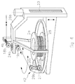
- FIG. 1 schematically represents a conventional sawing device, used before the present invention.
- Figure 2 is a schematic view of an embodiment of the sawing device according to the present invention.
- FIG. 3 is a schematic view of a detail of FIG. 2.
- Figures 4 and 5 are schematic views of two variants.
- the new wire 1 comes out of the supply reel 2 which is driven by a motor 3.
- a tension measurement 4 corrects a tension arm 5 coupled to a motor 6.
- the wire then passes into the sawing zone 40, around the wire guides 7 to form the sheet of wires 8.
- the workpiece 9 fixed on a support table 10 comes to bear against it to be sawn by the abrasive 11 coming from a distributor 12 and driven by the wires of the ply 8.
- the used wire 13 leaves the ply and returns to the take-up reel 14 via the tension arm 5, the tension measurement 4 and the transfer pulley 15 actuated back and forth sideways by the motor 16.
- the wire management device 41 therefore comprises coils 2 and 14 mounted to rotate about their axis.
- FIG. 2 schematically illustrates an embodiment of the present invention.
- the new wire 1 comes out of the supply reel 2a around which an arm 17 supporting pulleys 18,19,20,21 rotates.
- the motor of the arm 22 gives the tension to be applied to the wire 1, this tension being given by a measuring gauge 4.
- the wire 1 goes towards the sawing zone 40 composed of the same elements as in FIG. 1.
- the used wire 13 returns to the take-up reel 14a via the measuring gauge 4 and the rotary arm 17.
- the feed-back coils 2a and take-up 14a can be driven back and forth generated by a driving device 23 for cross-checking purposes.
- the wire management device 41a can be perfectly reversible.
- the coils 2a and 14a are fixedly mounted, not rotatable on any support.
- the arms 17 with their pulleys 18 to 21 each form a rotary member 42 for unwinding and / or rewinding rotatably mounted around the periphery of the reels and arranged so as to unwind and / or rewind the wire with a flow rate adjustable by the speed of the motors 22.
- the measuring gauges 4 are connected to the control of the motors 22, so that the rotary members 42 act as flow rate and thread tension regulators.
- FIG. 3 represents a possibility of producing the wire management device 41a according to the invention.
- the wire enters via a pulley 18, fixedly oriented and coupled to the tension gauge 4, coming from the sawing zone 40.
- the latter passes through a bearing 24 to which is fixed the tension arm 17 driven by the tension and rotation motor 22 fixed on a support 26. It passes around the pulleys 19 and 20 fixed relative to the arm and having parallel axes of rotation.
- the output pulley 21 can be rotatable relative to the shaft 25 to maintain a fixed orientation relative to the wire following the filling of the take-up reel 14.
- the bearing 24 supports the rotary arm 17 with its pulley system.
- the coil is driven back and forth generated by a mechanism 23 which can be electric, hydraulic, pneumatic or other.
- the pulleys 20, 21 therefore form a winding head 29 rotatably mounted around the periphery of one of the coils 2a, 14a.
- the pulley 21 constitutes a deflection member arranged to guide the wire coming from or ending at the spool in the direction of the pulley 20.
- the latter guides the wire towards the pulleys 19 and 18 which are arranged so that the wire is disposed substantially on the axis of rotation of the bearing 24, coincident with the axis of the coil. From the pulley 18, the wire then passes to the sawing zone 40.
- the pulley 20 has an axis of rotation such that a normal to this axis is substantially perpendicular to the axis of the coil. As the pulley 21 rotates around the shaft 25 the wire terminates substantially tangentially to the spool regardless of the degree of filling of the latter.
- FIG. 4 represents a variant making it possible to perform the function using a linear motor 27 rotating on a ring or a concentric circular rail 28 to coil 2a.
- the carriage 29b of the linear motor 27 forming the winding head supports the necessary pulleys 20b and 21b.
- the pulley 18b coupled to the tension gauge 4b, as well as the bearing 24b are fixedly mounted on the support 26b and the pulley 19b rotatable relative to the pulley 18b is fixed on the bearing 24b.
- the pulley 21b is rotatably mounted on the shaft 25b, while the pulley 20b has an axis of rotation fixed relative to the carriage 29b.
- the second variant shown in FIG. 5 comprises a support 26c and mobile support arm 26d carrying the fixed, non-rotating coil 2a.
- the motor 23d which can be of the mechanical, electrical, hydraulic, pneumatic or other type
- the support arm 26d can be moved vertically to perform the slicing function, corresponding to a transverse, axial reciprocating movement of the spool so as to wind the wire gradually.
- a ring concentric with the coil is formed by a ball bearing 30 comprising two rings.
- the winding head 29c is mounted on the inner ring 32 driven in rotation by the motor 31, for example as a function of the signals received from the tension gauge or from another control element.
- the pulleys 18c and 20c have axes of rotation with a fixed orientation relative to the support 26c, respectively to the winding head 29c, while the pulleys 19c and 21c are rotatably mounted relative to the support 26c thanks to the bearing 24c, respectively relative to the winding head 29c thanks at tree 25c.
- the coils 2a, 14a could be rotatably mounted on their support arm 26d (fig. 5) and driven in rotation to pass the wire at a continuous rate from the supply reel to the take-up reel. There would then be a first reciprocating movement of sawing the wire obtained thanks to the rotary members 42 with their winding head 29 and a second continuous movement of rewinding the wire on the take-up reel to compensate for the wear of the latter.
- the reciprocating sawing movement may then have a higher speed, for example 20 m / sec, than that of the continuous movement, for example 1 to 2 m / sec.
- the saw wire forming the sheet of wires 8 is made of spring steel with a diameter of between 0.1 and 0.2 mm in order to saw blocks of hard materials or more specific compositions, such as silicon, ceramic , composed of elements from groups III-V, GGG, sapphire, etc., in slices of 0.1 to 5mm thick approximately.
- the abrasive agent is a commercial product and can be diamond, silicon carbide, alumina, etc., in a form fixed to the wire or in free form in bubbling.
- the sawing device makes it possible, by the use of heavy coils 2a, 14a, containing long lengths of wire, to rationalize the sawing operation and to cut large-sized sawn pieces 9 while obtaining the necessary precision.
- the general concept of the machine is simplified, making it possible to obtain for the user, lower investment and more economical operation.
- the device for sawing may present in the sawing area only a single wire, instead of a sheet of son. It could also include a single non-rotating coil, either debtor or receiver, and another wire management device at the other end, for example a conical monoflasque coil.
- the bobbin cutting function could also be achieved by a transverse reciprocating movement of the winding head parallel to the axis of the coils.
- the pulleys 18 to 21 could be replaced by any other suitable return and guide member.
- the orientation of the axis of the coils 2a, 14a could be different, vertical or oblique.
Abstract
Description
La présente invention concerne un dispositif de sciage par fil comprenant une zone de sciage dans laquelle une pièce à scier est en appui contre le fil susceptible d'être déplacé selon un mouvement alternatif ou continu pour scier la pièce et un dispositif de gestion du fil comportant une bobine débitrice alimentant en fil neuf la zone de sciage et une bobine réceptrice reprenant le fil usé provenant de la zone de sciage.The present invention relates to a wire sawing device comprising a sawing zone in which a workpiece to be sawn is in abutment against the wire capable of being moved in an alternating or continuous movement to saw the workpiece and a wire management device comprising a supply reel supplying new wire to the sawing area and a take-up reel taking up the used wire coming from the sawing area.
Les dispositifs de sciage connus comprennent le plus souvent une nappe de fils susceptible de se déplacer selon un mouvement continu ou alternatif en appui contre une pièce à scier en tranches définissant ainsi une zone de sciage. La zone de sciage est constituée d'un ensemble de cylindres placés parallèlement. Ces cylindres appelés guide-fils, sont gravés avec des gorges définissant l'intervalle entre les fils de la nappe, soit l'épaisseur des tranches à scier. La pièce à scier est fixée sur une table support qui se déplace perpendiculairement à la nappe de fils. La vitesse de déplacement définie la vitesse de coupe. Le renouvellement du fil ainsi que le contrôle de la tension se fait dans une partie appelée "zone de gestion du fil" et située en dehors de la zone de sciage proprement dite. L'agent qui régira la découpe est soit un abrasif fixé sur le fil, soit un abrasif libre amené par barbotage. Le fil n'agit que comme transporteur.Known sawing devices most often comprise a sheet of wires capable of moving in a continuous or reciprocating movement pressing against a piece to be sawed in slices, thus defining a sawing zone. The sawing area consists of a set of cylinders placed in parallel. These cylinders, called wire guides, are engraved with grooves defining the interval between the wires of the sheet, that is to say the thickness of the slices to be sawed. The piece to be sawn is fixed on a support table which moves perpendicular to the wire table. The traveling speed defines the cutting speed. The wire renewal as well as the tension control is done in a part called "wire management area" and located outside the sawing area proper. The agent which will govern the cutting is either an abrasive fixed on the wire, or a free abrasive brought by bubbling. The wire acts only as a conveyor.
Le fil utilisé, même s'il n'agit que comme transporteur, subit une certaine usure qui devra être compensée par un taux de renouvellement qui sera définit par la surface sciée par unité de temps. Le développement actuel du sciage par fil est conduit par la tendance des utilisateurs de se diriger vers le sciage de grandes pièces, donc de grandes surfaces et par conséquent d'une grande consommation de fil. L'emploi de fils de grande longueur devient impératif.The wire used, even if it acts only as a conveyor, undergoes a certain wear which will have to be compensated by a rate of renewal which will be defined by the sawn surface per unit of time. The current development of wire sawing is driven by the tendency of users to move towards sawing large pieces, therefore large areas and therefore a large consumption of wire. The use of long wires becomes imperative.
Les systèmes de gestion du fil couramment utilisés dans les dispositifs de sciage sont réalisés par l'utilisation de bobines montées horizontalement ou verticalement sur un axe motorisé dont la vitesse est gérée par un dispositif régulant le débit et la tension de fil via une commande électronique. Le fil passera donc d'une bobine de fil neuf à la zone de sciage pour revenir après utilisation à une bobine de fil usagé. Dans une grande partie des cas, un mouvement de va-et-vient longitudinal dissymétrique est appliqué, la dissymétrie étant utilisée pour ajuster le taux de renouvellement. Le mouvement de va-et-vient longitudinal va imposer aux bobines de fil neuf et usagé des changements de direction fréquents avec de fortes accélérations. Si l'on ne veut pas augmenter la puissance des moteurs au delà du raisonnable, la limitation actuelle de ces dispositifs de sciage est donc déterminée par le poids des bobines de fil qu'il faut accélérer ou décélérer et par conséquent par la longueur de fil qui peut être gérée de cette manière. Une autre difficulté provient du fait que la bobine passe du poids plein au poids vide en cours de travail. Cette grande variation de poids perturbe les systèmes de régulation et rend plus difficile, si cela n'est impossible, le contrôle en général. De plus, si la longueur est limitée, le changement de fil devra s'effectuer plus fréquemment avec pour conséquence une manutention plus importante et une interruption du temps de production prolongée.The wire management systems commonly used in sawing devices are produced by the use of coils mounted horizontally or vertically on a motorized axis whose speed is managed by a device regulating the flow rate and the wire tension via an electronic control. The wire will therefore pass from a reel of new wire to the sawing area to return after use to a reel of used wire. In a large part of the cases, an asymmetrical longitudinal back-and-forth movement is applied, asymmetry being used to adjust the renewal rate. The longitudinal back and forth movement will impose on the reels of new and used wire frequent changes of direction with strong accelerations. If one does not want to increase the power of the motors beyond reasonable, the current limitation of these sawing devices is therefore determined by the weight of the wire spools which must be accelerated or decelerated and consequently by the length of wire. which can be managed this way. Another difficulty comes from the fact that the reel goes from full weight to empty weight during work. This large variation in weight disrupts the regulation systems and makes control, if not impossible, more general. In addition, if the length is limited, the wire change must be made more frequently with the consequence of greater handling and an interruption of the production time extended.
Des dispositifs de sciage par fil du type précité sont déjà connus spécialement dans l'industrie des composants électroniques, des ferrites, des quartz et silices, pour l'obtention en tranches fines de matériaux tels que le silicium poly-ou monocristallin ou les nouveaux matériaux tels que GaAs, InP, GGG (grenats de gadolinium-gallium) ou également quartz, saphir synthétique, et matériaux céramiques. Le prix élevé de ces matériaux rend le sciage par fil plus attractif comparativement à d'autres techniques comme le sciage par disque diamanté. Ces dispositifs de sciage par fil utilisent un fil en acier d'un diamètre généralement compris entre 0.1 et 0.2 mm, typiquement 0.18mm. La longueur courant est comprise entre 100 et 300 km donc d'un poids maximum de 60 kg, non compris la bobine support.Wire sawing devices of the aforementioned type are already known especially in the electronic components, ferrites, quartz and silica industry, for obtaining thin slices of materials such as poly or monocrystalline silicon or new materials. such as GaAs, InP, GGG (gadolinium-gallium garnets) or also quartz, synthetic sapphire, and ceramic materials. The high price of these materials makes wire sawing more attractive compared to other techniques such as diamond disc sawing. These wire sawing devices use a steel wire with a diameter generally between 0.1 and 0.2 mm, typically 0.18 mm. The running length is between 100 and 300 km, therefore with a maximum weight of 60 kg, not including the support coil.
La précision des pièces à scier, très importante pour des applications électroniques, dépend de la gestion du fil et de sa consommation. Le contrôle de la consommation permettra le contrôle de l usure du fil adapté aux exigences grandissantes de la technologie qui autorise la fabrication de pièces à scier de plus grand diamètre et de plus grande longueur. Cette tendance impose un contrôle de la consommation adapté à ces nouvelles possibilités et de ce fait nécessite l'emploi de fils de grande longueur peu propices aux systèmes actuels.The precision of the pieces to be sawed, which is very important for electronic applications, depends on the management of the wire and its consumption. The control of consumption will allow the control of the wear of the wire adapted to the increasing requirements of the technology which authorizes the manufacture of sawn pieces of larger diameter and greater length. This trend requires consumption control adapted to these new possibilities and this fact necessitates the use of very long wires which are not conducive to current systems.
Les buts de la présente invention consistent donc à remédier aux limitations des dispositifs de sciage connus, qui ne peuvent gérer que des longueurs limitées de fil, à supprimer le facteur d'inertie des bobines en rotation lors des grandes accélérations et décélérations, à rendre possible des longueurs de fils très importantes et à obtenir une précision de sciage élevée.The aims of the present invention therefore consist in overcoming the limitations of known sawing devices, which can only manage limited lengths of wire, in eliminating the inertia factor of the coils in rotation during large accelerations and decelerations, to make it possible very long wire lengths and to obtain high sawing precision.
Afin de réaliser ces buts, le dispositif selon la présente invention est caractérisé par le fait que le dispositif de gestion du fil comprend au moins un organe rotatif de débobinage et/ou de rembobinage monté de façon tournante autour de la périphérie de cette bobine et agencé de façon à débobiner et/ou rembobiner le fil avec un débit réglable.In order to achieve these goals, the device according to the present invention is characterized in that the thread management device comprises at least one rotary unwinding and / or rewinding member mounted in a rotatable manner around the periphery of this reel and arranged so as to unwind and / or rewind the wire with an adjustable rate.
Par ces caractéristiques, l'invention permet l'utilisation de bobines de fil lourdes ayant un grand diamètre sans que l'utilisation de moteurs de grande puissance soit nécessaire. Cela permettra également de travailler pendant de longues périodes sans intervention humaine, améliorant ainsi la productivité et la qualité. Par l'utilisation de bobines statiques, ou en tous cas sans rotation rapide, et en enroulant ou déroulant le fil par un dispositif tournant autour de celles-ci, l'inertie n'est alors plus dépendante du poids du fil ou de celui de la bobine, mais uniquement de celle du dispositif de bobinage ou débobinage qui peut lui, être réalisé aussi léger que possible. Les longueurs de fil deviennent uniquement limitées par la disponibilité du marché, et ainsi des bobines de 400 kg contenant jusqu'à 2000 km de fil de diamètre 0.18 sont rendues possibles.By these characteristics, the invention allows the use of coils of heavy wire having a large diameter without the use of high power motors being necessary. It will also allow you to work for long periods without human intervention, thereby improving productivity and quality. By the use of static coils, or in any case without rapid rotation, and by winding or unwinding the wire by a device rotating around them, the inertia is no longer dependent on the weight of the wire or that of the coil, but only that of the winding or unwinding device which can be made as light as possible. Wire lengths only become limited by market availability, and thus 400 kg spools containing up to 2000 km of 0.18 diameter wire are made possible.
L'utilisation de bobines de fil non rotatives permet donc de réaliser un dispositif de sciage par fil ayant une autonomie de fonctionnement étendue avec de très grandes longueurs de fil, sans que le système de contrôle du fil ne soit affecté par la masse de celui-ci. Cela permettra d'avoir un débit plus régulier, d'obtenir de plus grandes vitesses tout en gardant les avantages opérationnels et une grande précision de découpe.The use of non-rotating wire spools therefore makes it possible to produce a wire sawing device having an extended operating autonomy with very long lengths of wire, without the wire control system being affected by the mass thereof. this. This will make it possible to have a more regular flow, to obtain higher speeds while keeping the operational advantages and a high cutting precision.
Un mode d'exécution avantageux est caractérisé par le fait que le fil est agencé dans la zone de sciage sous forme d'une nappe de fils parallèles, par le fait que les deux bobines débitrice et réceptrice sont montées de façon non rotative sur un support et que le dispositif de gestion du fil comprend deux organes rotatifs montés de façon tournante autour des deux bobines et agencées de façon à agir comme régulateurs de débit et de tension du fil.An advantageous embodiment is characterized in that the wire is arranged in the sawing zone in the form of a sheet of parallel wires, in that the two supply and take-up coils are mounted in a non-rotatable manner on a support and that the wire management device comprises two rotary members rotatably mounted around the two coils and arranged so as to act as flow rate and wire tension regulators.
On obtient ainsi un dispositif de sciage d'une construction simple, d'un fonctionnement fiable, rapide, précis et entièrement indépendant du poids des deux bobines de fils et comportant une régulation du débit et de la tension du fil efficace, peu compliquée, et d'un prix de revient faible.A sawing device of a simple construction is thus obtained, of a reliable, fast, precise and entirely independent operation of the weight of the two spools of threads and comprising an efficient, uncomplicated regulation of the flow rate and of the tension of the thread, and of a low cost price.
Avantageusement, ledit organe rotatif comprend une tête de bobinage montée de façon tournante autour de la périphérie de la bobine et comportant au moins un premier élément de renvoi agencé à guider le fil provenant de ou aboutissant à la bobine en direction d'un second élément de renvoi.Advantageously, said rotary member comprises a winding head rotatably mounted around the periphery of the spool and comprising at least a first return element arranged to guide the wire coming from or ending at the spool in the direction of a second element of dismissal.
Ces caractéristiques permettent une construction très précise et peu compliquée.These characteristics allow a very precise and uncomplicated construction.
Le second élément de renvoi peut favorablement être agencé de façon que le fil soit disposé sensiblement sur l'axe de rotation dudit organe rotatif confondu avec l'axe de la bobine et agencé de façon à guider le fil en direction de la zone de sciage.The second deflection element can favorably be arranged so that the wire is disposed substantially on the axis of rotation of said rotary member coincides with the axis of the spool and arranged so as to guide the wire towards the sawing zone.
Cette disposition assure une conduite du fil très favorable et précise.This arrangement ensures very favorable and precise wire handling.
Selon une variante particulièrement avantageuse, le premier élément de renvoi comprend une première poulie dont une normale à l'axe de rotation est sensiblement perpendiculaire à l'axe de la bobine autour de laquelle elle tourne et une seconde poulie dont l'axe de rotation est monté tournant autour d'un arbre agencé de manière que le fil aboutisse de façon sensiblement tangentielle à la bobine quelque soit le degré de remplissage de cette dernière.According to a particularly advantageous variant, the first deflection element comprises a first pulley of which a normal to the axis of rotation is substantially perpendicular to the axis of the coil around which it rotates and a second pulley whose axis of rotation is mounted rotating around a shaft arranged so that the wire terminates substantially tangentially to the coil regardless of the degree of filling of the latter.
Le fil peut ainsi être enroulé et déroulé du début à la fin de la bobine, très régulièrement et avec une orientation précise.The wire can thus be wound and unwound from the beginning to the end of the spool, very regularly and with a precise orientation.
De manière avantageuse, l'organe rotatif comprend un bras équipé de ladite tête de bobinage et ayant pour axe de rotation l'axe de la bobine.Advantageously, the rotary member comprises an arm equipped with said winding head and having the axis of rotation as the axis of rotation.
On obtient par ces caractéristiques une construction simple et d'un prix de revient peu élevé.These characteristics give a simple construction and a low cost price.
Selon un variante, l'organe rotatif peut comprendre un anneau concentrique à la bobine et portant ladite tête de bobinage entraînée par un moteur en rotation sur l'anneau.Alternatively, the rotary member may comprise a ring concentric with the coil and carrying said winding head driven by a motor rotating on the ring.
Selon une autre variante, l'organe rotatif peut comprendre un anneau concentrique à la bobine formé par un roulement à deux bagues, la tête de bobinage étant fixée sur une des bagues entraînées en rotation par un moteur.According to another variant, the rotary member may comprise a ring concentric with the coil formed by a bearing with two rings, the winding head being fixed on one of the rings driven in rotation by a motor.
Ces variantes permettent d'obtenir un enroulement très précis et fiable.These variants make it possible to obtain a very precise and reliable winding.
Favorablement, la fonction de trancannage des bobines est réalisée par un mouvement de va-et-vient axial de celles-ci au moyen d un organe d'entraînement mécanique, électrique, hydraulique ou pneumatique.Advantageously, the function of slitting the coils is achieved by an axial reciprocating movement thereof by means of a mechanical, electrical, hydraulic or pneumatic drive member.
Le fil peut ainsi être enroulé de façon très régulière sur les bobines. Le mouvement de va-et-vient selon l axe de la bobine est appliqué, avec un amplitude qui est égale a la longueur de remplissage définie par la distance entre les flasques de la bobine.The wire can thus be wound very evenly on the spools. The back-and-forth movement along the axis of the coil is applied, with an amplitude which is equal to the filling length defined by the distance between the flanges of the coil.
En conclusion, le dispositif de sciage se présentera donc sous la forme de deux modules, l'un contenant la zone de sciage composé des cylindres guide-fils supportant la nappe de fils et de la table support qui se déplace perpendiculairement à la nappe de fils, l'autre contenant la gestion du fil, sera composé de support de bobines sur lesquels seront posées les bobines débitrice et réceptrice. Celles-ci pourront être animées d'un mouvement de va-et-vient pour réaliser l'opération de trancannage, à savoir le bobinage successif fil contre fil. A chacune des bobines de fil est attribué un système de bobinage ou de débobinage tournant autour de celle-ci. Cette fonction peut être réalisée par exemple par un bras tournant centré sur l'axe de la bobine ayant à ses extrémités un dispositif de poulies avec divers renvois ou par un rail extérieur supportant un chariot avec les poulies de renvoi.In conclusion, the sawing device will therefore be in the form of two modules, one containing the sawing zone composed of the wire guide cylinders supporting the wire ply and the support table which moves perpendicular to the wire ply , the other containing the wire management, will be made up of support of reels on which the delivery and reception coils will be posed. These may be driven back and forth to carry out the slicing operation, namely the successive winding wire against wire. Each of the spools of thread is assigned a winding or unwinding system rotating around it. This function can be achieved for example by a rotating arm centered on the axis of the coil having at its ends a pulley device with various references or by an external rail supporting a carriage with the pulleys.
D'autres avantages ressortent des caractéristiques exprimées dans les revendications dépendantes et de la description exposant ci-après l'invention plus en détail à l'aide de dessins qui représentent schématiquement et à titre d'exemple un mode d'exécution et des variantes.Other advantages emerge from the characteristics expressed in the dependent claims and from the description setting out the invention below in more detail with the aid of drawings which schematically represent, by way of example, an embodiment and variants.
La figure 1 représente schématiquement un dispositif de sciage conventionnel, utilisé avant la présente invention.FIG. 1 schematically represents a conventional sawing device, used before the present invention.
La figure 2 est une vue schématique d un mode d'exécution du dispositif de sciage selon la présente invention.Figure 2 is a schematic view of an embodiment of the sawing device according to the present invention.
La figure 3 est une vue schématique d'un détail de la figure 2.FIG. 3 is a schematic view of a detail of FIG. 2.
Les figures 4 et 5 sont des vues schématiques de deux variantes.Figures 4 and 5 are schematic views of two variants.
Dans la technique utilisée avant la présente invention illustrée à la figure 1, le fil neuf 1 sort de la bobine débitrice 2 qui est entraînée par un moteur 3. Une mesure de tension 4 corrige un bras de tension 5 accouplé à un moteur 6. Le fil passe alors dans la zone de sciage 40, autour des guide-fils 7 pour former la nappe de fils 8. La pièce à scier 9 fixée sur une table support 10 vient en appui contre celle-ci pour être sciée par l'abrasif 11 provenant d'un distributeur 12 et entraîné par les fils de la nappe 8. Le fil usé 13 sort de la nappe et retourne à la bobine réceptrice 14 par l'intermédiaire du bras de tension 5, de la mesure de tension 4 et de la poulie de trancannage 15 actionnée en va-et-vient latéral par le moteur 16. Le dispositif de gestion 41 du fil comprend donc des bobines 2 et 14 montées tournantes autour de leur axe.In the technique used before the present invention illustrated in FIG. 1, the
La figure 2 illustre schématiquement un mode d'exécution de la présente invention. Le fil neuf 1 sort de la bobine débitrice 2a autour de laquelle tourne un bras 17 supportant des poulies 18,19,20,21. Le moteur du bras 22 donne la tension à appliquer au fil 1, cette tension étant donnée par une jauge de mesure 4. Le fil 1 va vers la zone de sciage 40 composée des mêmes éléments qu'à la figure 1. Le fil usé 13 revient sur la bobine réceptrice 14a par l'intermédiaire de la jauge de mesure 4 et du bras rotatif 17. Les bobines débitrice 2a et réceptrice 14a peuvent être animées d'un mouvement de va-et-vient généré par un dispositif d'entraînement 23 à des fins de trancannage. Le dispositif de gestion du fil 41a peut être parfaitement réversible.Figure 2 schematically illustrates an embodiment of the present invention. The
Ainsi, les bobines 2a et 14a sont montées de façon fixe, non rotative sur un support quelconque. Les bras 17 avec leurs poulies 18 à 21 forment chacun un organe rotatif 42 de débobinage et/ou de rembobinage monté de façon tournante autour de la périphérie des bobines et agencé de façon à débobiner et/ou rembobiner le fil avec un débit réglable par la vitesse des moteurs 22. Les jauges de mesure 4 sont reliées à la commande des moteurs 22, de façon que les organes rotatifs 42 agissent comme régulateurs de débit et de tension du fil.Thus, the
La figure 3 représente une possibilité de réaliser le dispositif de gestion du fil 41a selon l'invention. Le fil entre par une poulie 18, fixement orientée et accouplée à la jauge de tension 4, en provenance de la zone de sciage 40. Celui-ci passe au travers d'un palier 24 auquel est fixé le bras de tension 17 entraîné par le moteur de tension et de rotation 22 fixé sur un support 26. Il passe autour des poulies 19 et 20 fixes par rapport au bras et ayant des axes de rotation parallèles. La poulie de sortie 21 peut être rotative par rapport à l'arbre 25 pour conserver une orientation fixe par rapport au fil suivant le remplissage de la bobine réceptrice 14. Le palier 24 supporte le bras rotatif 17 avec son système de poulies. La bobine est animée d'un mouvement de va-et-vient généré par un mécanisme 23 pouvant être électrique, hydraulique, pneumatique ou autre.FIG. 3 represents a possibility of producing the
Les poulies 20,21 forment donc une tête de bobinage 29 montée de façon tournante autour de la périphérie d'une des bobines 2a,14a. La poulie 21 constitue un organe de renvoi agencé à guider le fil provenant de ou aboutissant à la bobine en direction de la poulie 20. Cette dernière guide le fil vers les poulies 19 et 18 qui sont agencées de façon que le fil soit disposé sensiblement sur l'axe de rotation du palier 24, confondu avec l'axe de la bobine. De la poulie 18, le fil passe ensuite à la zone de sciage 40.The
La poulie 20 possède un axe de rotation tel qu'une normale à cet axe est sensiblement perpendiculaire à l'axe de la bobine. Comme la poulie 21 tourne autour de l'arbre 25 le fil aboutit de façon sensiblement tangentielle à la bobine quelque soit le degré de remplissage de cette dernière.The
La figure 4 représente une variante permettant de réaliser la fonction en utilisant un moteur linéaire 27 en rotation sur un anneau ou un rail circulaire 28 concentrique à la bobine 2a. Le chariot 29b du moteur linéaire 27 formant la tête de bobinage supporte les poulies nécessaires 20b et 21b. La poulie 18b accouplée à la jauge de tension 4b, ainsi que le palier 24b sont montés fixes sur le support 26b et la poulie 19b rotative par rapport à la poulie 18b est fixée sur le palier 24b. La poulie 21b est montée tournante sur l'arbre 25b, tandis que la poulie 20b comporte un axe de rotation fixe par rapport au chariot 29b.FIG. 4 represents a variant making it possible to perform the function using a
La seconde variante représentée à la figure 5 comprend un support 26c et bras de support mobile 26d portant la bobine 2a fixe, non rotative. Grâce au moteur 23d, qui peut être de type mécanique, électrique, hydraulique, pneumatique ou autre, le bras de support 26d peut être déplacé verticalement pour effectuer la fonction de trancannage, correspondant à un mouvement de va-et-vient transversal, axial de la bobine de façon à enrouler le fil progressivement. Un anneau concentrique à la bobine est formé par un roulement à billes 30 comportant deux bagues. La tête de bobinage 29c est montée sur la bague intérieure 32 entraînée en rotation par le moteur 31, par exemple en fonction des signaux reçus de la jauge de tension ou d'un autre élément de commande.The second variant shown in FIG. 5 comprises a
Comme précédemment décrit les poulies 18c et 20 c possèdent des axes de rotation à orientation fixe par rapport au support 26c, respectivement à la tête de bobinage 29c, tandis que les poulies 19c et 21c sont montées de façon tournante par rapport au support 26c grâce au palier 24c, respectivement par rapport à la tête de bobinage 29c grâce a l'arbre 25c.As previously described the
Selon une troisième variante, les bobines 2a, 14a pourraient être montées de façon tournante sur leur bras de support 26d (fig. 5) et entraînées en rotation pour faire passer le fil suivant un débit continu de la bobine débitrice vers la bobine réceptrice. On aurait alors un premier mouvement alternatif de sciage du fil obtenu grâce aux organes rotatifs 42 avec leur tête de bobinage 29 et un second mouvement continu de rembobinage du fil sur la bobine réceptrice pour compenser l'usure de ce dernier. Le mouvement de sciage alternatif pourra alors avoir une vitesse plus grande, par exemple 20m/sec, que celle du mouvement continu, par exemple 1 à 2m/sec.In a third variant, the
De façon générale, le fil de sciage formant la nappe de fils 8 est constituée d'acier à ressort d'un diamètre compris entre 0.1 et 0.2 mm afin de scier des blocs de matériaux durs ou de compositions plus particulières, tels que silicium, céramique, composés des éléments des groupes III-V, GGG, saphir, etc, en tranches de 0.1 à 5mm d'épaisseur environ. L'agent abrasif est un produit du commerce et peut être du diamant, du carbure de silicium, de l'alumine etc, sous forme fixée au fil ou sous forme libre en barbotage.In general, the saw wire forming the sheet of
Le dispositif de sciage permet par l'utilisation de bobines 2a,14a lourdes, contenant de grandes longueurs de fil, de rationaliser l'opération de sciage et de découper des pièces à scier 9 de grandes dimensions tout en obtenant la précision nécessaire. De plus, le concept général de la machine se trouve simplifié, permettant d'obtenir pour l'utilisateur un investissement plus faible et une exploitation plus économique.The sawing device makes it possible, by the use of
Il est bien entendu que le mode de réalisation et les variantes décrits ci-dessus ne présentent aucun caractère limitatif et qu'ils peuvent recevoir toutes modifications désirables à l'intérieur du cadre tel que défini par la revendications 1. En particulier, le dispositif de sciage pourra présenter dans la zone de sciage uniquement un seul fil, au lieu d'une nappe de fils. Il pourrait également comporter une seule bobine non rotative soit débitrice soit réceptrice et un autre dispositif de gestion de fils à l'autre bout, par exemple une bobine conique monoflasque. La fonction de trancannage des bobines pourrait également être réalisée par un mouvement de va-et-vient transversal de la tête de bobinage parallèlement à l'axe des bobines. Les poulies 18 à 21 pourraient être remplacées par tout autre organe de renvoi et de guidage adéquats. L'orientation de l'axe des bobines 2a,14a pourrait être différente, verticale ou oblique.It is understood that the embodiment and the variants described above have no limiting character and that they can receive any desirable modifications within the framework as defined by
Claims (12)
Applications Claiming Priority (3)
| Application Number | Priority Date | Filing Date | Title |
|---|---|---|---|
| CH2777/95 | 1995-10-03 | ||
| CH277795 | 1995-10-03 | ||
| CH02777/95A CH691292A5 (en) | 1995-10-03 | 1995-10-03 | Wire sawing device equipped with a wire management system allowing the use of wire coils of very great length. |
Publications (2)
| Publication Number | Publication Date |
|---|---|
| EP0767036A1 true EP0767036A1 (en) | 1997-04-09 |
| EP0767036B1 EP0767036B1 (en) | 2002-11-13 |
Family
ID=4241372
Family Applications (1)
| Application Number | Title | Priority Date | Filing Date |
|---|---|---|---|
| EP96115198A Expired - Lifetime EP0767036B1 (en) | 1995-10-03 | 1996-09-21 | Wire saw having a wire management system allowing for wire rollers of very large length |
Country Status (5)
| Country | Link |
|---|---|
| US (1) | US5829424A (en) |
| EP (1) | EP0767036B1 (en) |
| JP (1) | JPH09109013A (en) |
| CH (1) | CH691292A5 (en) |
| DE (1) | DE69624769T2 (en) |
Cited By (7)
| Publication number | Priority date | Publication date | Assignee | Title |
|---|---|---|---|---|
| EP0990498A1 (en) * | 1998-09-10 | 2000-04-05 | Wacker Siltronic Gesellschaft für Halbleitermaterialien Aktiengesellschaft | Method and device for cutting wafers from a hard brittle ingot |
| CN102101325A (en) * | 2010-12-15 | 2011-06-22 | 湖南宇晶机器实业有限公司 | Radial balance mechanism for automatic wire arranging device of multi-wire cutting machine |
| EP2586554A1 (en) * | 2011-10-27 | 2013-05-01 | Applied Materials Switzerland Sàrl | Wire saw device with two independent wire webs and method thereof |
| US8490658B2 (en) | 2009-02-26 | 2013-07-23 | Saint-Gobain Abrasives, Inc. | Automatic winding of wire field in wire slicing machine |
| CN104647622A (en) * | 2015-02-11 | 2015-05-27 | 苏州硅峰太阳能科技有限公司 | Oscillating efficient multi-thread squarer for silicon ingot |
| CN106239747A (en) * | 2016-08-26 | 2016-12-21 | 浙江顺联智能设备有限公司 | Diamond wire cutting machine |
| CN108972924A (en) * | 2018-07-18 | 2018-12-11 | 阜宁协鑫光伏科技有限公司 | Silicon wafer diced system |
Families Citing this family (29)
| Publication number | Priority date | Publication date | Assignee | Title |
|---|---|---|---|---|
| CZ283541B6 (en) * | 1996-03-06 | 1998-04-15 | Trimex Tesla, S.R.O. | Process of cutting ingots from hard materials to plates and a saw for making the same |
| JPH1110509A (en) * | 1997-06-24 | 1999-01-19 | Nippei Toyama Corp | Mechanism for applying tension to wire saw |
| JPH11165250A (en) * | 1997-12-08 | 1999-06-22 | Tokyo Seimitsu Co Ltd | Wire saw |
| JP4049900B2 (en) * | 1998-08-20 | 2008-02-20 | 株式会社スーパーシリコン研究所 | Wire saw cutting device |
| DE60033574T2 (en) | 2000-05-31 | 2007-11-15 | Memc Electronic Materials S.P.A. | WIRE SAW AND METHOD FOR SIMULTANEOUS CUTTING OF SEMICONDUCTOR BARRIER |
| US6889684B2 (en) | 2002-11-06 | 2005-05-10 | Seh America, Inc. | Apparatus, system and method for cutting a crystal ingot |
| CH696806A5 (en) * | 2003-11-18 | 2007-12-14 | Walter Ebner | wire saw reciprocates. |
| DE102007016316A1 (en) | 2007-04-04 | 2008-10-09 | Siemens Ag | Method and system for separating a plurality of ceramic devices from a device block |
| EP2110216B1 (en) * | 2008-04-14 | 2013-06-05 | Applied Materials, Inc. | Wire saw device and method for operating same |
| KR101625709B1 (en) * | 2010-02-08 | 2016-05-30 | 토요 어드밴스드 테크놀로지스 컴퍼니 리미티드 | Method of cutting workpiece with wire saw and wire saw |
| WO2011096019A1 (en) * | 2010-02-08 | 2011-08-11 | トーヨーエイテック株式会社 | Wire saw |
| DE102011082366B3 (en) * | 2011-09-08 | 2013-02-28 | Siltronic Ag | Single-layer winding of saw wire with fixed cutting grain for wire saws for separating slices from a workpiece |
| EP2583804A1 (en) * | 2011-10-22 | 2013-04-24 | Applied Materials Switzerland Sàrl | A new wafer sawing system |
| FR2988023A1 (en) * | 2012-03-16 | 2013-09-20 | Sodetal Sas | SAW WIRE, METHOD FOR MANUFACTURING SUCH WIRE, AND USE |
| JP2013220482A (en) * | 2012-04-13 | 2013-10-28 | Tokyo Seiko Co Ltd | Wire-type cutting device |
| US20150114189A1 (en) * | 2012-09-17 | 2015-04-30 | Jon Khachaturian | Method and apparatus for removing underwater platforms |
| CN106862663B (en) * | 2012-12-04 | 2019-01-04 | 梅耶博格(瑞士)公司 | wire management system |
| CN103224166B (en) * | 2013-05-15 | 2017-02-08 | 长沙岱勒新材料科技股份有限公司 | High-speed winding machine |
| CN103448153B (en) * | 2013-08-23 | 2016-02-03 | 蓝思科技股份有限公司 | A kind of cutting technique of sapphire ingot and processing jig thereof |
| JP5994766B2 (en) * | 2013-11-21 | 2016-09-21 | 信越半導体株式会社 | Work cutting method |
| DE102015200198B4 (en) * | 2014-04-04 | 2020-01-16 | Siltronic Ag | Method for cutting semiconductor wafers from a workpiece with a saw wire |
| EP3023184A1 (en) | 2014-11-20 | 2016-05-25 | Meyer Burger AG | Method and device for cutting workpieces |
| CN104608264B (en) * | 2015-02-11 | 2016-08-24 | 苏州硅峰太阳能科技有限公司 | Swing marble multi-line cutting machine |
| CN105057823A (en) * | 2015-08-01 | 2015-11-18 | 烟台力凯电子科技有限公司 | Tension swing arm limiting column device of multi-wire sawing machine |
| JP6923828B2 (en) * | 2015-09-15 | 2021-08-25 | キヤノンマーケティングジャパン株式会社 | Wire electric discharge machine |
| TWI713832B (en) * | 2017-04-28 | 2020-12-21 | 友達晶材股份有限公司 | Wafer slicing machine and its take-up and unwinding device and wafer slicing method |
| WO2019008530A1 (en) | 2017-07-07 | 2019-01-10 | Meyer Burger (Switzerland) Ag | Method of winding a cutting wire |
| US10593537B1 (en) | 2019-03-21 | 2020-03-17 | Samuel Messinger | Longitudinal silicon ingot slicing machine and jig fixture |
| US11276577B2 (en) | 2019-03-21 | 2022-03-15 | Samuel Messinger | Longitudinal silicon ingot slicing apparatus |
Citations (4)
| Publication number | Priority date | Publication date | Assignee | Title |
|---|---|---|---|---|
| US778059A (en) * | 1903-03-05 | 1904-12-20 | Inocencio Fernandez | Machine for cutting diamonds. |
| FR1591125A (en) * | 1968-10-17 | 1970-04-27 | ||
| US3841297A (en) * | 1971-12-01 | 1974-10-15 | Motorola Inc | Machine for cutting brittle materials |
| JPH07195263A (en) * | 1993-12-29 | 1995-08-01 | Nippei Toyama Corp | Wire guide device |
Family Cites Families (3)
| Publication number | Priority date | Publication date | Assignee | Title |
|---|---|---|---|---|
| US3843072A (en) * | 1973-02-12 | 1974-10-22 | Western Electric Co | Method of and apparatus for coiling wire |
| US5465917A (en) * | 1994-05-23 | 1995-11-14 | Kosch; Delmar D. | Welding wire dispenser with adjustable brake |
| JP3107143B2 (en) * | 1995-07-14 | 2000-11-06 | 株式会社東京精密 | Wire traverse device for wire saw |
-
1995
- 1995-10-03 CH CH02777/95A patent/CH691292A5/en not_active IP Right Cessation
-
1996
- 1996-09-21 EP EP96115198A patent/EP0767036B1/en not_active Expired - Lifetime
- 1996-09-21 DE DE69624769T patent/DE69624769T2/en not_active Expired - Lifetime
- 1996-10-02 US US08/724,927 patent/US5829424A/en not_active Expired - Lifetime
- 1996-10-03 JP JP8281296A patent/JPH09109013A/en active Pending
Patent Citations (4)
| Publication number | Priority date | Publication date | Assignee | Title |
|---|---|---|---|---|
| US778059A (en) * | 1903-03-05 | 1904-12-20 | Inocencio Fernandez | Machine for cutting diamonds. |
| FR1591125A (en) * | 1968-10-17 | 1970-04-27 | ||
| US3841297A (en) * | 1971-12-01 | 1974-10-15 | Motorola Inc | Machine for cutting brittle materials |
| JPH07195263A (en) * | 1993-12-29 | 1995-08-01 | Nippei Toyama Corp | Wire guide device |
Non-Patent Citations (1)
| Title |
|---|
| PATENT ABSTRACTS OF JAPAN vol. 95, no. 008 * |
Cited By (11)
| Publication number | Priority date | Publication date | Assignee | Title |
|---|---|---|---|---|
| EP0990498A1 (en) * | 1998-09-10 | 2000-04-05 | Wacker Siltronic Gesellschaft für Halbleitermaterialien Aktiengesellschaft | Method and device for cutting wafers from a hard brittle ingot |
| US6390896B1 (en) | 1998-09-10 | 2002-05-21 | WACKER SILTRONIC GESELLSCHAFT FüR HALBLEITERMATERIALIEN AG | Method and device for cutting a multiplicity of disks from a hard brittle workpiece |
| US8490658B2 (en) | 2009-02-26 | 2013-07-23 | Saint-Gobain Abrasives, Inc. | Automatic winding of wire field in wire slicing machine |
| CN102101325A (en) * | 2010-12-15 | 2011-06-22 | 湖南宇晶机器实业有限公司 | Radial balance mechanism for automatic wire arranging device of multi-wire cutting machine |
| CN102101325B (en) * | 2010-12-15 | 2014-05-21 | 湖南宇晶机器实业有限公司 | Radial balance mechanism for automatic wire arranging device of multi-wire cutting machine |
| EP2586554A1 (en) * | 2011-10-27 | 2013-05-01 | Applied Materials Switzerland Sàrl | Wire saw device with two independent wire webs and method thereof |
| CN103085182A (en) * | 2011-10-27 | 2013-05-08 | 应用材料瑞士有限责任公司 | Wire Saw Device With Two Independent Wire Webs, Wire Saw Device And Novel Concept Of Method Thereof |
| CN104647622A (en) * | 2015-02-11 | 2015-05-27 | 苏州硅峰太阳能科技有限公司 | Oscillating efficient multi-thread squarer for silicon ingot |
| CN106239747A (en) * | 2016-08-26 | 2016-12-21 | 浙江顺联智能设备有限公司 | Diamond wire cutting machine |
| CN108972924A (en) * | 2018-07-18 | 2018-12-11 | 阜宁协鑫光伏科技有限公司 | Silicon wafer diced system |
| CN108972924B (en) * | 2018-07-18 | 2020-07-17 | 阜宁协鑫光伏科技有限公司 | Silicon wafer cutting system |
Also Published As
| Publication number | Publication date |
|---|---|
| EP0767036B1 (en) | 2002-11-13 |
| US5829424A (en) | 1998-11-03 |
| DE69624769T2 (en) | 2003-07-17 |
| DE69624769D1 (en) | 2002-12-19 |
| JPH09109013A (en) | 1997-04-28 |
| CH691292A5 (en) | 2001-06-29 |
Similar Documents
| Publication | Publication Date | Title |
|---|---|---|
| EP0767036B1 (en) | Wire saw having a wire management system allowing for wire rollers of very large length | |
| EP0808701B1 (en) | Wire saw | |
| EP0040145A1 (en) | Apparatus for cutting long fibres, particularly glass fibres | |
| EP0788857B1 (en) | Wire sawing device | |
| FR2620117A1 (en) | DIVIDING AND REENROUTING STRIP MACHINES | |
| EP0281511A1 (en) | Thread-cutting apparatus | |
| EP1054748B1 (en) | Wire sawing device for cutting fine slices using angular crossing of at least two sawing yarn layers | |
| EP1464461B1 (en) | Process and device for wire sawing | |
| EP1437209B1 (en) | Wire sawing device | |
| EP0788858B1 (en) | Wire sawing device | |
| EP1941985B1 (en) | Method of supplying rubber to a rubber-consuming device and facility for supplying rubber to this rubber-consuming device | |
| EP1711423B1 (en) | Double driving roll winding device for continuous rolling machine with controlled application load of the driving rolls | |
| EP0788859A1 (en) | Wire sawing device | |
| EP0328610B1 (en) | Process for cropping bars of hard materials and equipment for carrying out the process | |
| FR2529871A1 (en) | Machine for coating any surface with a composite material made from fibres and resin. | |
| CH694182A5 (en) | Wire sawing device. | |
| EP1555101A1 (en) | Wire saw device | |
| EP0000853B1 (en) | Winding machine, in particular for thermoplastic yarns | |
| EP0002976B1 (en) | Apparatus for continuously machining helicoidal grooves in a cylindrical object | |
| WO1991004839A1 (en) | Method and device for tensioning a cutting wire in a cutting machine-tool | |
| FR2757793A1 (en) | ABRASIVE BAND MACHINING MACHINE OF INTERNAL SURFACES OF REVOLUTIONARY PARTS | |
| CH696757A5 (en) | Process and wire sawing device. | |
| FR2722127A1 (en) | METHOD AND DEVICE FOR CUTTING PHOTOGRAPHIC PRODUCTS INTO BANDS | |
| EP0056541B1 (en) | Support for machining a cylindrical workpiece, and machining head provided with such a support | |
| EP0572719B1 (en) | Electro-erosion machine with an improved circuit for unwinding the electrode wire |
Legal Events
| Date | Code | Title | Description |
|---|---|---|---|
| PUAI | Public reference made under article 153(3) epc to a published international application that has entered the european phase |
Free format text: ORIGINAL CODE: 0009012 |
|
| AK | Designated contracting states |
Kind code of ref document: A1 Designated state(s): DE FR GB IT |
|
| 17P | Request for examination filed |
Effective date: 19970715 |
|
| RAP1 | Party data changed (applicant data changed or rights of an application transferred) |
Owner name: HCT SHAPING SYSTEMS SA |
|
| RIN1 | Information on inventor provided before grant (corrected) |
Inventor name: HAUSER, CHARLES |
|
| GRAG | Despatch of communication of intention to grant |
Free format text: ORIGINAL CODE: EPIDOS AGRA |
|
| 17Q | First examination report despatched |
Effective date: 20020215 |
|
| GRAG | Despatch of communication of intention to grant |
Free format text: ORIGINAL CODE: EPIDOS AGRA |
|
| GRAH | Despatch of communication of intention to grant a patent |
Free format text: ORIGINAL CODE: EPIDOS IGRA |
|
| GRAH | Despatch of communication of intention to grant a patent |
Free format text: ORIGINAL CODE: EPIDOS IGRA |
|
| GRAA | (expected) grant |
Free format text: ORIGINAL CODE: 0009210 |
|
| AK | Designated contracting states |
Kind code of ref document: B1 Designated state(s): DE FR GB IT |
|
| REG | Reference to a national code |
Ref country code: GB Ref legal event code: FG4D Free format text: NOT ENGLISH |
|
| REF | Corresponds to: |
Ref document number: 69624769 Country of ref document: DE Date of ref document: 20021219 |
|
| GBT | Gb: translation of ep patent filed (gb section 77(6)(a)/1977) |
Effective date: 20030213 |
|
| PLBE | No opposition filed within time limit |
Free format text: ORIGINAL CODE: 0009261 |
|
| STAA | Information on the status of an ep patent application or granted ep patent |
Free format text: STATUS: NO OPPOSITION FILED WITHIN TIME LIMIT |
|
| 26N | No opposition filed |
Effective date: 20030814 |
|
| REG | Reference to a national code |
Ref country code: FR Ref legal event code: CD |
|
| PGFP | Annual fee paid to national office [announced via postgrant information from national office to epo] |
Ref country code: IT Payment date: 20100922 Year of fee payment: 15 Ref country code: FR Payment date: 20101005 Year of fee payment: 15 |
|
| PGFP | Annual fee paid to national office [announced via postgrant information from national office to epo] |
Ref country code: GB Payment date: 20100921 Year of fee payment: 15 |
|
| PGFP | Annual fee paid to national office [announced via postgrant information from national office to epo] |
Ref country code: DE Payment date: 20100922 Year of fee payment: 15 |
|
| GBPC | Gb: european patent ceased through non-payment of renewal fee |
Effective date: 20110921 |
|
| PG25 | Lapsed in a contracting state [announced via postgrant information from national office to epo] |
Ref country code: IT Free format text: LAPSE BECAUSE OF NON-PAYMENT OF DUE FEES Effective date: 20110921 |
|
| REG | Reference to a national code |
Ref country code: FR Ref legal event code: ST Effective date: 20120531 |
|
| REG | Reference to a national code |
Ref country code: DE Ref legal event code: R119 Ref document number: 69624769 Country of ref document: DE Effective date: 20120403 |
|
| PG25 | Lapsed in a contracting state [announced via postgrant information from national office to epo] |
Ref country code: DE Free format text: LAPSE BECAUSE OF NON-PAYMENT OF DUE FEES Effective date: 20120403 |
|
| PG25 | Lapsed in a contracting state [announced via postgrant information from national office to epo] |
Ref country code: FR Free format text: LAPSE BECAUSE OF NON-PAYMENT OF DUE FEES Effective date: 20110930 Ref country code: GB Free format text: LAPSE BECAUSE OF NON-PAYMENT OF DUE FEES Effective date: 20110921 |