EP0767017B1 - Nutenstanzmaschine - Google Patents
Nutenstanzmaschine Download PDFInfo
- Publication number
- EP0767017B1 EP0767017B1 EP96115786A EP96115786A EP0767017B1 EP 0767017 B1 EP0767017 B1 EP 0767017B1 EP 96115786 A EP96115786 A EP 96115786A EP 96115786 A EP96115786 A EP 96115786A EP 0767017 B1 EP0767017 B1 EP 0767017B1
- Authority
- EP
- European Patent Office
- Prior art keywords
- workpiece
- notching press
- punching
- press according
- gear
- Prior art date
- Legal status (The legal status is an assumption and is not a legal conclusion. Google has not performed a legal analysis and makes no representation as to the accuracy of the status listed.)
- Expired - Lifetime
Links
Images


Classifications
-
- B—PERFORMING OPERATIONS; TRANSPORTING
- B23—MACHINE TOOLS; METAL-WORKING NOT OTHERWISE PROVIDED FOR
- B23Q—DETAILS, COMPONENTS, OR ACCESSORIES FOR MACHINE TOOLS, e.g. ARRANGEMENTS FOR COPYING OR CONTROLLING; MACHINE TOOLS IN GENERAL CHARACTERISED BY THE CONSTRUCTION OF PARTICULAR DETAILS OR COMPONENTS; COMBINATIONS OR ASSOCIATIONS OF METAL-WORKING MACHINES, NOT DIRECTED TO A PARTICULAR RESULT
- B23Q16/00—Equipment for precise positioning of tool or work into particular locations not otherwise provided for
- B23Q16/001—Stops, cams, or holders therefor
-
- B—PERFORMING OPERATIONS; TRANSPORTING
- B21—MECHANICAL METAL-WORKING WITHOUT ESSENTIALLY REMOVING MATERIAL; PUNCHING METAL
- B21D—WORKING OR PROCESSING OF SHEET METAL OR METAL TUBES, RODS OR PROFILES WITHOUT ESSENTIALLY REMOVING MATERIAL; PUNCHING METAL
- B21D28/00—Shaping by press-cutting; Perforating
- B21D28/02—Punching blanks or articles with or without obtaining scrap; Notching
- B21D28/22—Notching the peripheries of circular blanks, e.g. laminations for dynamo-electric machines
-
- H—ELECTRICITY
- H02—GENERATION; CONVERSION OR DISTRIBUTION OF ELECTRIC POWER
- H02K—DYNAMO-ELECTRIC MACHINES
- H02K15/00—Processes or apparatus specially adapted for manufacturing, assembling, maintaining or repairing of dynamo-electric machines
- H02K15/02—Processes or apparatus specially adapted for manufacturing, assembling, maintaining or repairing of dynamo-electric machines of stator or rotor bodies
- H02K15/021—Magnetic cores
-
- Y—GENERAL TAGGING OF NEW TECHNOLOGICAL DEVELOPMENTS; GENERAL TAGGING OF CROSS-SECTIONAL TECHNOLOGIES SPANNING OVER SEVERAL SECTIONS OF THE IPC; TECHNICAL SUBJECTS COVERED BY FORMER USPC CROSS-REFERENCE ART COLLECTIONS [XRACs] AND DIGESTS
- Y10—TECHNICAL SUBJECTS COVERED BY FORMER USPC
- Y10T—TECHNICAL SUBJECTS COVERED BY FORMER US CLASSIFICATION
- Y10T29/00—Metal working
- Y10T29/49—Method of mechanical manufacture
- Y10T29/49002—Electrical device making
- Y10T29/49009—Dynamoelectric machine
- Y10T29/49012—Rotor
-
- Y—GENERAL TAGGING OF NEW TECHNOLOGICAL DEVELOPMENTS; GENERAL TAGGING OF CROSS-SECTIONAL TECHNOLOGIES SPANNING OVER SEVERAL SECTIONS OF THE IPC; TECHNICAL SUBJECTS COVERED BY FORMER USPC CROSS-REFERENCE ART COLLECTIONS [XRACs] AND DIGESTS
- Y10—TECHNICAL SUBJECTS COVERED BY FORMER USPC
- Y10T—TECHNICAL SUBJECTS COVERED BY FORMER US CLASSIFICATION
- Y10T83/00—Cutting
- Y10T83/444—Tool engages work during dwell of intermittent workfeed
- Y10T83/4539—Means to change tool position, or length or datum position of work- or tool-feed increment
- Y10T83/4541—With means to vary magnitude of work-feed increment
- Y10T83/4549—By change in length of one member of feed-driving linkage
- Y10T83/4551—Rotating member
-
- Y—GENERAL TAGGING OF NEW TECHNOLOGICAL DEVELOPMENTS; GENERAL TAGGING OF CROSS-SECTIONAL TECHNOLOGIES SPANNING OVER SEVERAL SECTIONS OF THE IPC; TECHNICAL SUBJECTS COVERED BY FORMER USPC CROSS-REFERENCE ART COLLECTIONS [XRACs] AND DIGESTS
- Y10—TECHNICAL SUBJECTS COVERED BY FORMER USPC
- Y10T—TECHNICAL SUBJECTS COVERED BY FORMER US CLASSIFICATION
- Y10T83/00—Cutting
- Y10T83/444—Tool engages work during dwell of intermittent workfeed
- Y10T83/4607—With rotary work-carrier
Definitions
- the invention relates to a slot punching machine, in particular for Stamping of stator, rotor, core and the like grooved Sheets for electrical machines and transformers.
- stator and rotor sheets for electrical machines and transformer sheets are different procedures from practice known.
- a single Stator and rotor sheets are gradually stamped out received a single sheet metal blank.
- the individual grooves of the each belonging to the later stator or rotor plate Section of the blank successively punched.
- the rotor punching machine is from the DE-A-29 19 687 known.
- This slot punching machine has a fixed groove punch with interchangeable Tools to which a dividing head is assigned.
- the Dividing device is used to hold one to be machined Workpiece by a disc-shaped circuit board (Sheet metal blank) is formed.
- the disk-shaped board is from the divider in a horizontal plane held and rotatably supported about a vertical axis.
- the Dividing device moves the workpiece in steps by Vertical axis, the grooving punch after each adjustment step a groove punches.
- To adapt to different Sheet or workpiece diameter is the dividing head away from the grooving punch and adjustable stored.
- DE-C2-26 04 639 is a tool arrangement for producing grooved sheet metal segments known a stationary groove punch with attached has a fixed machine bed. On the machine bed sits on the slot punch and adjustable away from it a dividing device for mounting and angular Setting the core sheet to be punched.
- the slot punching machine has a machine bed, on which one is preferably designed as a sub-apparatus Workpiece holding device is mounted stationary.
- the punching device is on the machine bed adjustable and is therefore towards the dividing head and slidable away from it. By being able the distance between the dividing head and the punching device work pieces can be different Diameter can be processed.
- the workpiece is always in the same place on the stationary one Divided apparatus, so that also stator or rotor sheets with a small diameter are easily accessible.
- the punch of the slot punching machine is during the Operation of the cutting or punching process floating stored.
- the punching device is used to machine these workpieces moved closer to the dividing head, while otherwise arranged further away from this is.
- the dividing head is replaced by a corresponding one Machine table provided with clamping devices and changes its position when setting the workpiece size Not.
- the punching device is supported by a low-friction and rigid storage facility on the machine bed. Due to the low friction, especially a low one Stiction, a very precise adjustment of the distance between the punching device and the machine table enables. This makes the prerequisite for one high processing accuracy on the workpiece.
- the rigidity of the storage facility creates the prerequisite for a high working speed of the punching device, those with high mass accelerations, acceleration forces and the resulting shock loads the storage facility.
- Gear means provided that at a short distance from the Workpiece between the punching device and the machine table is arranged.
- the gearbox determines the Distance between the punching device and the machine table. Vibrations or other deformations of the Machine bed, the machine table and in particular of the punching device influence the set one Distance almost not. Warps or deflections of the machine bed, for example as a result of heating the Machine bed at its top if its bottom stays cool, do not lead to a corresponding Change in distance of the punching device from the machine table.
- the distance is rather from the gear means certainly.
- Other, by forces or by heat The changes in length caused are the same the storage facility and affect the accuracy little in the manufacture of the core sheets or not.
- the gear means can preferably be a threaded spindle be designed as a ball screw.
- the ball screw is rotatable on the workpiece holding device, for example stored, with a ball nut with the punching device connected is.
- the distance between the rotatable end bearing of the ball screw and the mother defines the effective length of the Gear means or, in the specific case, the threaded spindle. If this effective length with the distance of the axis of rotation of the dividing head (workpiece holder) and corresponds to the punching tool punching the grooves, can the influence of temperature changes on the machining accuracy be reduced. At the same Temperature change of the workpiece and the spindle are also their changes in length about the same, so that the Punching process with good accuracy on the intended Job is done.
- the gear means in particular the threaded spindle is arranged in this way that during the operation of the punching machine Can reach ambient temperature. This can can be achieved by the gear means or the threaded spindle exposed, i.e. exposed to the ambient air, is arranged.
- the gear is against Insulated heat sources of the punching machine. Isolation can already be achieved, for example, by a massive connection between heat sources and the Ball nut or a corresponding gear element is waived. It is assumed that Workpieces due to storage ambient temperature exhibit. If the ball screw also ambient temperature assumes there is temperature equality. Temperature changes over the course of a working day thus affect due to the same length changes the machining accuracy little or not.
- the threaded spindle with its longitudinal axis in short distance from the workpiece to be machined is a particularly rigid coupling of the Punching device reached on the dividing head.
- the distance between the two is of vibrations and deformations the other grooving machine largely unaffected.
- the Threaded spindle or generally set of the gear means Distance by fixing the punching device the machine bed
- the gear means i.e. especially the ball screw
- this braking device should be such that the threaded spindle at actuated brake device is held non-rotatably. Shocks or vibrations caused by the operation of the grooving device occur must be recorded safely without twisting the threaded spindle. In this case the distance between the dividing heads and groove punching device and thus the radius of the punching grooves set reliably and precisely.
- Spring mechanism which is preferably electrical is particularly rigid and precise Blocking of the threaded spindle can be reached.
- the actuation brake shoes belonging to the disc brake takes place orthogonal to the direction of rotation, so that a once set the rotational position of the threaded spindle does not shift the actuation of the brake shoes or is moved.
- roller guide trained storage facility allows a low-friction and in particular almost free of static friction Moving the punching device on the machine bed.
- Sliding elements provided when out of order located. Punching device at a short distance corresponding slideways are standing or without pressing force concern about these. This between the sliding elements and the slideways mostly present little play causes almost when moving the punching device no friction occurs.
- vibrations caused by the operation of the punching device become elastic deformations of the rollers or other rolling elements.
- the sliding elements are put on the slideways on and / or are pressed against them, which on the one hand is a rigid coupling of the punching device conditioned on the machine bed and on the other hand the Released rolling elements. This prevents the destruction of the Rolling elements and deformation of the raceways.
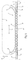
- FIG. 1 A slot punching machine is shown schematically in FIG 1 for punching stator or rotor sheets for electrical Machines shown as in FIG. 3 emerge.
- the slot punching machine 1 has one a punch 3 mounted on a machine bed 2. This is supported on the machine bed 2 via storage devices 4 and in the direction indicated by arrow 5 movable.
- the punch 3 is shown on the right in FIG. 1 Provide a punch 7 on the front, that is used in a sequence of punching operations a blank 8 shown in FIG. 2 which is shown in FIG. 3 illustrated sheets, namely a stator 10 and a Form rotor plate 11.
- the punching tool points to this 7 an upper tool 14 fastened to a tappet 13 and a lower tool 15.
- the upper tool 14 and that Lower tool 15 are designed to be complementary to one another and they have the outer contour of the one shown in FIG. Recesses 16 to be punched out of the blank 8 on.
- the finished core sheet is that on the right in FIG. 1 shown front of the punch 3 opposite a dividing device 19 arranged fixed to the machine bed 2 is connected and as a workpiece holder serves.
- the dividing device 19 has a tensioning device 21 to accommodate the blank 8.
- the jig 21 is about a vertical axis arranged parallel to the axis 17 22 rotatably mounted.
- the dividing head 19 enables thus a rotation of the blank 8 about the vertical axis 22 and advance through the blank 8 selected angular positions between press strokes.
- a linear drive is provided for setting the distance between the punch 3 and the dividing head 19 and thus the distance between the axis 17 and the Vertical axis 22.
- a linear drive is provided for setting the distance between the punch 3 and the dividing head 19 and thus the distance between the axis 17 and the Vertical axis 22, a linear drive is provided.
- a preloaded backlash-free ball screw 23 used in Fig. 1 by its horizontal axis of rotation 24 is indicated.
- the axis of rotation 24 intersects the axis 17 and the vertical axis 22 each at a right angle Intersection points 25, 26.
- Near intersection point 26 is Ball screw 23 rotatably mounted. Near the Intersection 25 is connected to the punch 3, Ball screw not shown arranged. The distance between the rotatable bearing (intersection 26) and the ball nut (intersection 25) is in substantially equal to the distance between the axis 17 and the vertical axis 22.
- the ball screw 23 is with a handwheel or connected to an electric actuator that a targeted rotation and thus an adjustment of the Distance between the punch 3 and the dividing device 19th enables.
- To the drive device not shown belongs to a disc brake 27 that on their Braking or blocking position is resiliently biased. An electrical release device enables targeted Release the disc brake 27.
- the slot punching machine 1 described so far works as follows:
- the disc brake 27 solved by appropriate control and the electrical Drive is controlled so that the distance between the axis 17 and the vertical axis 22 the desired Machining radius assumes. This can, for example Air gap radius of the core sheets to be produced. To the disc brake 27 is applied, whereby the distance between the punch 3 and the Sub-apparatus 19 is fixed.
- the punch 3 rolls along with the distance adjustment their storage facilities 4 on the machine bed 2 with low friction and almost free of static friction. Even after it is done Blocking of the ball screw 23 is the punch 3 not firmly bound to the machine bed 2.
- the distance between the axis 17 and the vertical axis 22 defined solely by the ball screw 23.
- the distance between the intersection points 25, 26 Defined active length of the ball screw 23 is correct essentially with the machining radius (air gap radius) the stator and rotor plates match. This has to Consequence that temperature changes for machining accuracy are without influence, provided only the ball screw 23 and the blank 8 a substantially have the same temperature. To ensure this is the ball screw 23 over almost their entire active length or at least a substantial section the same free.
- the ball screw is located in this area with ambient air and takes in essentially their temperature.
- the ones to be processed Workpieces (blanks 8) usually have storage in the vicinity of the grooving machine 1 the same temperature.
- the bearing device 4 is shown in detail in FIG. 4 shown. It is the storage facility 4 a combined roller and slide bearing device. As Rolling elements serve rollers 28, which are on a machine bed 2 provided career path 29 run. The punch 3 is also on its underside with a roller track 31 provided, which rests on the rollers 28. The Roller track 31 is via corresponding diversion channels 32, 33 and a roller return channel, which is only indicated symbolically 34 closed to one circulation. To the Entry and exit of the rollers 28 in and out of Diverter channels 32, 33 serve fittings 35, 36 which too both ends of the track 31 are arranged.
- sliding elements 37, 38 on both sides arranged, each firmly with corresponding parts the punch 3 are connected.
- the sliding element 37 has one of the plan trained career 29 in small Distance opposite flat bottom 41. Between the bottom 41 and the raceway 29 is a gap of about two hundredths of a millimeter. In Vertical direction, which is shown in FIG. 4 by an arrow 42 is indicated, the sliding element 37 is extremely rigid. Its rigidity is considerably greater than that of the Punch 3 supporting rollers 28.
- Lubrication device 44 in the simplest case can be formed by an oil pan, the storage facilities 4 supplied in excess of oil. In particular the between the sliding elements 37, 38 and the track 29 each gap formed is filled with oil.
- the Lubrication device can also be designed in another way be to achieve good damping properties however, at least the gap should lead to oil.
- the storage device 4 described so far is both with low friction and almost no friction towards the arrow 5 movable and very stiff.
- the Bottom sides 41, 43 of the sliding elements 37, 38 are not on the career track 29 and in particular are not on pressed this.
- the weight of the punch 3 is alone on those in turn supported on the track 29 Rolls 28.
- a slot punching machine 1 provided the necessary grooves successively punched into a disc-shaped blank 8.
- the slot punching machine has a stationary one Machine bed 2 on the one end
- Dividing apparatus 19 for receiving the blank 8 carries.
- a punch 3 stored in Regarding the dividing head 19 is adjustable on the Machine bed 2 a punch 3 stored.
- the distance between the dividing device 19 and the punch 3 is by means of a ball screw 23 adjustable between the dividing device and the punch 3 acts.
- the fixation a set distance is done by blocking the ball screw 23, preferably by means of a Disc brake 27.
- the punch 3 is combined with a Roll-slide bearing mounted on the machine bed 2, which enables the punch 3 to be moved with little friction and which also stores them stiffly.
- the combination of the low-friction bearing device with the preferably close ball screw 23 arranged on blank 8 enables precise setting of the desired Machining radius and permanent compliance with the same. For precision and to compensate for temperature fluctuations also contributes to the ball screw 23 in thermal Contact with the environment.
Landscapes
- Engineering & Computer Science (AREA)
- Mechanical Engineering (AREA)
- Manufacturing & Machinery (AREA)
- Power Engineering (AREA)
- Press Drives And Press Lines (AREA)
- Presses And Accessory Devices Thereof (AREA)
- Manufacture Of Motors, Generators (AREA)
Description
- Fig.1
- eine Nutenstanzmaschine zum Stanzen von Stator- oder Rotorblechen für elektrische Maschinen, in Seitenansicht und in schematisierter Prinzipdarstellung,
- Fig. 2
- einen auf der Nutenstanzmaschine nach Fig. 1 zu bearbeitenden Rohling für Stator- oder Rotorbleche für elektrische Maschinen, in Draufsicht und in einem anderen Maßstab,
- Fig. 3
- einen aus dem Rohling nach Fig. 2 ausgestanzten Satz von Stator- oder Rotorblechen, in schematisierter Darstellung und in Draufsicht, und
- Fig. 4
- eine zu der Nutenstanzmaschine nach Fig. 1 gehörige steife und reibungsarme Lagereinrichtung, in schematisierter Seitenansicht und in einem anderen Maßstab.
Claims (13)
- Nutenstanzmaschine (1), insbesondere zum Stanzen von Stator- und Rotorblechen für elektrische Maschinen,dadurch gekennzeichnet, dass das Getriebemittel (23) derart frei angeordnet ist, daß es während des Betriebes der Stanzmaschine (1) Umgebungstemperatur annehmen kann.mit einem ortsfest lagerbaren längliche Maschinenbett (2), an dessen einem Ende oberseitig eine Werkstückhalteeinrichtung (19) angeordnet ist,mit an der Werkstückhalteeinrichlung (19) vorgesehenen Spannmitteln (21) zum Aufspannnen und Positionieren von Werkstücken (8),mit einer Stanzeinrichtung (3), die auf dem Maschinenbett (2) in einer Richtung (5) von der Werkstückhalteeinrichtung (19) weg und auf die Werkstückhalteeinrichtung (19) zu längsverstellbar angeordnet ist und die mit einem Werkzeug (7) zur Bearbeitung des Werkstückes (8) ausrüstbar ist,mit einer reibungsarmen, steifen Lagereinrichtung (4), die zwischen dem Maschinenbett (2) und der Stanzeinrichtung (3) angeordnet ist,mit einem Getriebemittel (23) zur Einstellung des Abstandes zwischen der Werkstückhalteeinrichtung (19) und der Stanzeinrichtung (3), das sich mit einem Ende an der Werkstückhalteeinrichtung (19) in der Nähe der Spannmittel (21) und mit seinem anderen Ende an der Stanzeinrichtung (3) in der Nähe des Werkzeuges (7) abstützt, wobeidie Stanzeinrichtung (3) bei im Betrieb arretiertem Getriebemittel (23) schwimmend auf dem Maschinenbett (2) gelagert ist, wobei das Getriebemittel (23) gegen Wärmequellen der Stanzmaschine (1) isoliert ist,
- Nutenstanzmaschine nach Anspruch 1 , dadurch gekennzeichnet, daß die Werkstückhalteeinrichtung (19) ein Teilapparat ist, mit dem ein gespanntes Werkstück (8) schrittweise um eine Achse (22) drehbar und wahlweise arretierbar ist.
- Nutenstanzmaschine nach Anspruch 1 , dadurch gekennzeichnet, daß das Getriebemittel (23) eine Gewindespindel ist.
- Nutenstanzmaschine nach Anspruch 1 , dadurch gekennzeichnet, daß das Getriebemittel (23) eine wirksame Länge aufweist, die im wesentlichen mit einem bei der Stanzbearbeitung des Werkstückes einzuhaltenden Sollmaß übereinstimmt.
- Nutenstanzmaschine nach Anspruch 1 , dadurch gekennzeichnet, daß das Getriebemittel (23) an der Stanzmaschine (1) exponiert angeordnet ist.
- Nutenstanzmaschine nach Anspruch 3 , dadurch gekennzeichnet, daß die Gewindespindel (23) mit ihrer Längsachse (24) in geringem Abstand zu dem zu bearbeitenden Werkstück (8) angeordnet ist.
- Nutenstanzmaschine nach Anspruch 3 , dadurch gekennzeichnet, daß die Gewindespindel mit einer steuerbaren Bremseinrichtung (27) verbunden ist.
- Nutenstanzmaschine nach Anspruch 7 , dadurch gekennzeichnet, daß die Leistungsfähigkeit der Bremseinrichtung (27) derart bemessen ist, daß die Gewindespindel bei betätigter Bremseinrichtung (27) auch bei während des Betriebes der Nutenstanzmaschine (1) auftretenden Vibrationen unverdrehbar gehalten ist.
- Nutenstanzmaschine nach Anspruch 8 , dadurch gekennzeichnet, daß die Bremseinrichtung (27) eine Scheibenbremse mit Federspeicher ist.
- Nutenstanzmaschine nach Anspruch 1 , dadurch gekennzeichnet, daß die Lagereinrichtung (4) ein Wälzlager mit einer auf Druck beanspruchbaren Aussteifung ist.
- Nutenstanzmaschine nach Anspruch 1 , dadurch gekennzeichnet, daß die Stanzeinrichtung (3) über die Lagereinrichtung und eine Gleiteinrichtung (37, 38) gelagert ist.
- Nutenstanzmaschine nach Anspruch 1 , dadurch gekennzeichnet, daß die Lagereinrichtung (4) eine Rollenführung mit zusätzlichen Gleitelementen (37, 38) ist.
- Nutenstanzmaschine nach Anspruch 12, dadurch gekennzeichnet, daß die Gleitelemente (37, 38) mit einem Spiel in Bezug auf eine ihnen zugeordnete Gleitbahn (29) angeordnet sind, das geringer ist als die maximal mögliche elastische Verformung der Rollen (28).
Applications Claiming Priority (2)
| Application Number | Priority Date | Filing Date | Title |
|---|---|---|---|
| DE19537475A DE19537475A1 (de) | 1995-10-07 | 1995-10-07 | Nutenstanzmaschine |
| DE19537475 | 1995-10-07 |
Publications (2)
| Publication Number | Publication Date |
|---|---|
| EP0767017A1 EP0767017A1 (de) | 1997-04-09 |
| EP0767017B1 true EP0767017B1 (de) | 2001-11-28 |
Family
ID=7774334
Family Applications (1)
| Application Number | Title | Priority Date | Filing Date |
|---|---|---|---|
| EP96115786A Expired - Lifetime EP0767017B1 (de) | 1995-10-07 | 1996-10-02 | Nutenstanzmaschine |
Country Status (3)
| Country | Link |
|---|---|
| US (1) | US5911806A (de) |
| EP (1) | EP0767017B1 (de) |
| DE (2) | DE19537475A1 (de) |
Families Citing this family (13)
| Publication number | Priority date | Publication date | Assignee | Title |
|---|---|---|---|---|
| DE10040978A1 (de) * | 2000-08-22 | 2002-03-21 | Schuler Held Lasertechnik Gmbh | Vorrichtung und Verfahren zur Herstellung von Blechpaketen |
| EP2047923A1 (de) * | 2007-10-09 | 2009-04-15 | Galbiati Group S.r.l. | Stanzmaschine zum Stanzen von Metallblechen |
| EP2165783B1 (de) * | 2008-09-17 | 2012-08-01 | TRUMPF Werkzeugmaschinen GmbH + Co. KG | Werkzeug für eine Stanzmaschine zum Verändern des Spannungszustands eines Blechs |
| CN102814423B (zh) * | 2012-08-10 | 2015-06-17 | 芜湖金鹰机械科技开发有限公司 | 轴颈环形气缸退料装置及退料方法 |
| AU356953S (en) * | 2014-01-17 | 2014-08-20 | Shachihata Inc | Stamp molding machine |
| CN107206459B (zh) * | 2014-08-15 | 2019-11-05 | 尼得科梵姆科公司 | 用于薄板工件的制造的方法 |
| WO2016058063A1 (pt) * | 2014-10-15 | 2016-04-21 | Weg Equipamentos Elétricos S.A.-Motores | Máquina para estampagem contínua de chapas segmentadas |
| CN105666099A (zh) * | 2016-03-16 | 2016-06-15 | 泰信电机(苏州)有限公司 | 一种电机衬套压入装置 |
| DE102016008924A1 (de) | 2016-07-19 | 2018-01-25 | Aweba Werkzeugbau Gmbh Aue | Temperierendes Umformwerkzeug |
| DE102017124336A1 (de) | 2017-10-18 | 2019-04-18 | Hsf Automation Gmbh | Werkzeugvorrichtung, Vorrichtung zum Nutenstanzen und Verfahren zum Betreiben einer Vorrichtung zum Nutenstanzen |
| DE102017124334A1 (de) | 2017-10-18 | 2019-04-18 | Hsf Automation Gmbh | Vorrichtung zum Nutenstanzen und Stanzsystem |
| DE102017124335A1 (de) | 2017-10-18 | 2019-04-18 | Hsf Automation Gmbh | Antriebsvorrichtung, Vorrichtung zum Nutenstanzen und Verfahren zum Antreiben einer Vorrichtung zum Nutenstanzen |
| CN118971537B (zh) * | 2024-08-05 | 2025-05-13 | 金华赛利科智能科技有限公司 | 一种用于无刷电机定子与转子的压装装置 |
Family Cites Families (12)
| Publication number | Priority date | Publication date | Assignee | Title |
|---|---|---|---|---|
| CH576298A5 (de) * | 1973-09-05 | 1976-06-15 | Weingarten Ag Maschf | |
| DE2353730C3 (de) * | 1973-10-26 | 1978-03-16 | Maschinenfabrik Weingarten Ag, 7987 Weingarten | Einrichtung zum Stanzen von Platinen für konische Rotor- und Statorpakete von Elektromotoren |
| DE2411439B2 (de) * | 1974-03-09 | 1976-01-15 | Maschinenfabrik Weingarten Ag, 7987 Weingarten | Stanzmaschine zum nuten von dynamoblechen, die einen grossen radius aufweisen und in kreisringsegmente zerlegt sind |
| US3906826A (en) * | 1974-03-29 | 1975-09-23 | Bmr Enterprises | Workpiece indexing apparatus for machine tools |
| DE2604639C2 (de) * | 1976-02-06 | 1985-11-14 | L. Schuler GmbH, 7320 Göppingen | Werkzeuganordnung zum Herstellen von genuteten Blechsegmenten |
| DE2919687A1 (de) * | 1979-05-16 | 1980-11-20 | Schuler Gmbh L | Numerisch gesteuerte nutenstanzmaschine |
| JPS5629614U (de) * | 1979-08-14 | 1981-03-20 | ||
| DE3429692A1 (de) * | 1984-08-11 | 1986-02-20 | Werner & Kolb Werkzeugmasch Gm | Fuehrungselement fuer bewegte maschinenteile |
| EP0171700B1 (de) * | 1984-08-14 | 1990-04-04 | MAHO Aktiengesellschaft | Einstellbare Wälzkörperumlauf-Geradführung |
| US4602541A (en) * | 1984-12-06 | 1986-07-29 | Trumpf Gmbh & Co. | Punch press with means for rotating the workpiece and method of using same and tooling therefor |
| EP0307080B1 (de) * | 1987-07-28 | 1992-06-03 | LUCAS INDUSTRIES public limited company | Fahrzeugscheibenbremse mit Flüssigkeitskühlung |
| US4879894A (en) * | 1988-06-06 | 1989-11-14 | Roper Whitney Company | Press with movable workpiece support carrier |
-
1995
- 1995-10-07 DE DE19537475A patent/DE19537475A1/de not_active Withdrawn
-
1996
- 1996-10-02 EP EP96115786A patent/EP0767017B1/de not_active Expired - Lifetime
- 1996-10-02 DE DE59608307T patent/DE59608307D1/de not_active Expired - Lifetime
- 1996-10-03 US US08/725,165 patent/US5911806A/en not_active Expired - Lifetime
Also Published As
| Publication number | Publication date |
|---|---|
| DE19537475A1 (de) | 1997-04-10 |
| US5911806A (en) | 1999-06-15 |
| EP0767017A1 (de) | 1997-04-09 |
| DE59608307D1 (de) | 2002-01-10 |
Similar Documents
| Publication | Publication Date | Title |
|---|---|---|
| EP2874804B1 (de) | Keiltrieb | |
| EP0037096B1 (de) | Vorrichtung nach Art einer Stanze oder Presse | |
| EP0767017B1 (de) | Nutenstanzmaschine | |
| DE3990963C2 (de) | Einstellbares Wälzkörperumlauflager für lineare Bewegung | |
| EP2903790B1 (de) | Verfahren und werkzeugeinheit zur einstellung eines stanzspalts | |
| EP2756893A1 (de) | Materialbearbeitungsvorrichtung, insbesondere eine Umformmaschine | |
| EP0418779A1 (de) | Verfahren zum Herstellen von Werkstücken durch Schneiden, insbesondere in einem Konterschneidwerkzeug | |
| EP1287918B1 (de) | Verfahren und Vorrichtung zur Bildung einer dreiseitig begrenzten Ecke aus einem ebenflächigen, plattenförmigen Material | |
| EP3265304B1 (de) | Pulverpresse sowie ein futtergehäuse mit vorzugsweise mehreren für ein querpressen verschiebbaren stempeln | |
| DE2741576A1 (de) | Bearbeitungsmaschine fuer draht und band, insbesondere stanz- und biegeautomat, mit mehreren werkzeugebenen | |
| EP2329944B1 (de) | Presse zum Erzeugen einer Druckkraft für die Bearbeitung eines Werkstückes | |
| EP3481565B1 (de) | Streckbiegemaschine und verfahren zum verformen eines werkstückes | |
| EP1884303B1 (de) | Verfahren zum Zentrieren von Werkstücken sowie Vorrichtung zur Durchführung eines solchen Verfahrens | |
| EP0294765B1 (de) | Präzisionsstanzautomat und zugehöriges Verfahren zum Werkzeugwechsel | |
| DE10019788A1 (de) | Werkzeugmaschine | |
| DE10135233A1 (de) | Ringmaschine | |
| EP1035936A1 (de) | Vorrichtung und Verfahren zum Bruchtrennen von Werkstücken | |
| DE69934374T2 (de) | Umformwerkzeug und Verwendung dieses Werkzeuges zum Walzformen eines Werkstückes | |
| DE4410483A1 (de) | Säulenführungsgestell und Presse zum Antreiben desselben | |
| DE202022103820U1 (de) | Umformmaschine zum Drücken und Drückwalzen | |
| DE3544087C2 (de) | ||
| DE10017378B4 (de) | Qualitätssicherungssystem | |
| DE60102959T2 (de) | Kreissägemaschine zum Sägen von Platten mit stufenloser Verstellung des Spieles zwischen einem Schlitten und seiner Führungsschiene | |
| EP1663564A1 (de) | Schweisszange | |
| EP1632308A1 (de) | Linearbewegungsführung mit zwei parallelen Führungsschienen und Verfahren zu deren Herstellung |
Legal Events
| Date | Code | Title | Description |
|---|---|---|---|
| PUAI | Public reference made under article 153(3) epc to a published international application that has entered the european phase |
Free format text: ORIGINAL CODE: 0009012 |
|
| AK | Designated contracting states |
Kind code of ref document: A1 Designated state(s): CH DE FR GB IT LI SE |
|
| 17P | Request for examination filed |
Effective date: 19970731 |
|
| RAP1 | Party data changed (applicant data changed or rights of an application transferred) |
Owner name: SCHULER PRESSEN GMBH & CO. KG |
|
| 17Q | First examination report despatched |
Effective date: 20000322 |
|
| GRAG | Despatch of communication of intention to grant |
Free format text: ORIGINAL CODE: EPIDOS AGRA |
|
| GRAG | Despatch of communication of intention to grant |
Free format text: ORIGINAL CODE: EPIDOS AGRA |
|
| GRAH | Despatch of communication of intention to grant a patent |
Free format text: ORIGINAL CODE: EPIDOS IGRA |
|
| GRAH | Despatch of communication of intention to grant a patent |
Free format text: ORIGINAL CODE: EPIDOS IGRA |
|
| GRAA | (expected) grant |
Free format text: ORIGINAL CODE: 0009210 |
|
| AK | Designated contracting states |
Kind code of ref document: B1 Designated state(s): CH DE FR GB IT LI SE |
|
| REG | Reference to a national code |
Ref country code: CH Ref legal event code: EP |
|
| REG | Reference to a national code |
Ref country code: GB Ref legal event code: IF02 |
|
| REF | Corresponds to: |
Ref document number: 59608307 Country of ref document: DE Date of ref document: 20020110 |
|
| REG | Reference to a national code |
Ref country code: CH Ref legal event code: NV Representative=s name: CABINET ROLAND NITHARDT CONSEILS EN PROPRIETE INDU |
|
| GBT | Gb: translation of ep patent filed (gb section 77(6)(a)/1977) |
Effective date: 20020201 |
|
| ET | Fr: translation filed | ||
| PGFP | Annual fee paid to national office [announced via postgrant information from national office to epo] |
Ref country code: GB Payment date: 20020919 Year of fee payment: 7 |
|
| PLBE | No opposition filed within time limit |
Free format text: ORIGINAL CODE: 0009261 |
|
| STAA | Information on the status of an ep patent application or granted ep patent |
Free format text: STATUS: NO OPPOSITION FILED WITHIN TIME LIMIT |
|
| PGFP | Annual fee paid to national office [announced via postgrant information from national office to epo] |
Ref country code: FR Payment date: 20021018 Year of fee payment: 7 |
|
| PGFP | Annual fee paid to national office [announced via postgrant information from national office to epo] |
Ref country code: CH Payment date: 20021024 Year of fee payment: 7 |
|
| PGFP | Annual fee paid to national office [announced via postgrant information from national office to epo] |
Ref country code: SE Payment date: 20021025 Year of fee payment: 7 |
|
| 26N | No opposition filed | ||
| PG25 | Lapsed in a contracting state [announced via postgrant information from national office to epo] |
Ref country code: GB Free format text: LAPSE BECAUSE OF NON-PAYMENT OF DUE FEES Effective date: 20031002 |
|
| PG25 | Lapsed in a contracting state [announced via postgrant information from national office to epo] |
Ref country code: SE Free format text: LAPSE BECAUSE OF NON-PAYMENT OF DUE FEES Effective date: 20031003 |
|
| PG25 | Lapsed in a contracting state [announced via postgrant information from national office to epo] |
Ref country code: LI Free format text: LAPSE BECAUSE OF NON-PAYMENT OF DUE FEES Effective date: 20031031 Ref country code: CH Free format text: LAPSE BECAUSE OF NON-PAYMENT OF DUE FEES Effective date: 20031031 |
|
| GBPC | Gb: european patent ceased through non-payment of renewal fee |
Effective date: 20031002 |
|
| EUG | Se: european patent has lapsed | ||
| REG | Reference to a national code |
Ref country code: CH Ref legal event code: PL |
|
| PG25 | Lapsed in a contracting state [announced via postgrant information from national office to epo] |
Ref country code: FR Free format text: LAPSE BECAUSE OF NON-PAYMENT OF DUE FEES Effective date: 20040630 |
|
| REG | Reference to a national code |
Ref country code: FR Ref legal event code: ST |
|
| PG25 | Lapsed in a contracting state [announced via postgrant information from national office to epo] |
Ref country code: IT Free format text: LAPSE BECAUSE OF NON-PAYMENT OF DUE FEES;WARNING: LAPSES OF ITALIAN PATENTS WITH EFFECTIVE DATE BEFORE 2007 MAY HAVE OCCURRED AT ANY TIME BEFORE 2007. THE CORRECT EFFECTIVE DATE MAY BE DIFFERENT FROM THE ONE RECORDED. Effective date: 20051002 |
|
| PGFP | Annual fee paid to national office [announced via postgrant information from national office to epo] |
Ref country code: DE Payment date: 20140926 Year of fee payment: 19 |
|
| REG | Reference to a national code |
Ref country code: DE Ref legal event code: R119 Ref document number: 59608307 Country of ref document: DE |
|
| PG25 | Lapsed in a contracting state [announced via postgrant information from national office to epo] |
Ref country code: DE Free format text: LAPSE BECAUSE OF NON-PAYMENT OF DUE FEES Effective date: 20160503 |