EP0767005A1 - Rotary atomizing head type painting device - Google Patents
Rotary atomizing head type painting device Download PDFInfo
- Publication number
- EP0767005A1 EP0767005A1 EP96908347A EP96908347A EP0767005A1 EP 0767005 A1 EP0767005 A1 EP 0767005A1 EP 96908347 A EP96908347 A EP 96908347A EP 96908347 A EP96908347 A EP 96908347A EP 0767005 A1 EP0767005 A1 EP 0767005A1
- Authority
- EP
- European Patent Office
- Prior art keywords
- ring
- atomizing head
- rotary atomizing
- coating machine
- shaping air
- Prior art date
- Legal status (The legal status is an assumption and is not a legal conclusion. Google has not performed a legal analysis and makes no representation as to the accuracy of the status listed.)
- Granted
Links
Images


Classifications
-
- B—PERFORMING OPERATIONS; TRANSPORTING
- B05—SPRAYING OR ATOMISING IN GENERAL; APPLYING FLUENT MATERIALS TO SURFACES, IN GENERAL
- B05B—SPRAYING APPARATUS; ATOMISING APPARATUS; NOZZLES
- B05B5/00—Electrostatic spraying apparatus; Spraying apparatus with means for charging the spray electrically; Apparatus for spraying liquids or other fluent materials by other electric means
- B05B5/025—Discharge apparatus, e.g. electrostatic spray guns
- B05B5/04—Discharge apparatus, e.g. electrostatic spray guns characterised by having rotary outlet or deflecting elements, i.e. spraying being also effected by centrifugal forces
-
- B—PERFORMING OPERATIONS; TRANSPORTING
- B05—SPRAYING OR ATOMISING IN GENERAL; APPLYING FLUENT MATERIALS TO SURFACES, IN GENERAL
- B05B—SPRAYING APPARATUS; ATOMISING APPARATUS; NOZZLES
- B05B5/00—Electrostatic spraying apparatus; Spraying apparatus with means for charging the spray electrically; Apparatus for spraying liquids or other fluent materials by other electric means
- B05B5/025—Discharge apparatus, e.g. electrostatic spray guns
- B05B5/053—Arrangements for supplying power, e.g. charging power
- B05B5/0533—Electrodes specially adapted therefor; Arrangements of electrodes
-
- B—PERFORMING OPERATIONS; TRANSPORTING
- B05—SPRAYING OR ATOMISING IN GENERAL; APPLYING FLUENT MATERIALS TO SURFACES, IN GENERAL
- B05B—SPRAYING APPARATUS; ATOMISING APPARATUS; NOZZLES
- B05B5/00—Electrostatic spraying apparatus; Spraying apparatus with means for charging the spray electrically; Apparatus for spraying liquids or other fluent materials by other electric means
- B05B5/025—Discharge apparatus, e.g. electrostatic spray guns
- B05B5/04—Discharge apparatus, e.g. electrostatic spray guns characterised by having rotary outlet or deflecting elements, i.e. spraying being also effected by centrifugal forces
- B05B5/0403—Discharge apparatus, e.g. electrostatic spray guns characterised by having rotary outlet or deflecting elements, i.e. spraying being also effected by centrifugal forces characterised by the rotating member
- B05B5/0407—Discharge apparatus, e.g. electrostatic spray guns characterised by having rotary outlet or deflecting elements, i.e. spraying being also effected by centrifugal forces characterised by the rotating member with a spraying edge, e.g. like a cup or a bell
-
- B—PERFORMING OPERATIONS; TRANSPORTING
- B05—SPRAYING OR ATOMISING IN GENERAL; APPLYING FLUENT MATERIALS TO SURFACES, IN GENERAL
- B05B—SPRAYING APPARATUS; ATOMISING APPARATUS; NOZZLES
- B05B5/00—Electrostatic spraying apparatus; Spraying apparatus with means for charging the spray electrically; Apparatus for spraying liquids or other fluent materials by other electric means
- B05B5/025—Discharge apparatus, e.g. electrostatic spray guns
- B05B5/04—Discharge apparatus, e.g. electrostatic spray guns characterised by having rotary outlet or deflecting elements, i.e. spraying being also effected by centrifugal forces
- B05B5/0426—Means for supplying shaping gas
-
- B—PERFORMING OPERATIONS; TRANSPORTING
- B05—SPRAYING OR ATOMISING IN GENERAL; APPLYING FLUENT MATERIALS TO SURFACES, IN GENERAL
- B05B—SPRAYING APPARATUS; ATOMISING APPARATUS; NOZZLES
- B05B15/00—Details of spraying plant or spraying apparatus not otherwise provided for; Accessories
- B05B15/50—Arrangements for cleaning; Arrangements for preventing deposits, drying-out or blockage; Arrangements for detecting improper discharge caused by the presence of foreign matter
Definitions
- This invention relates to a rotary atomizing head type coating machine with an indirect charging system, which is particularly suitable for use with low resistance paints such as water-base paints and metallic paints.
- a rotary atomizing head type coating machine while a rotary atomizing head is put in high speed rotation, a high voltage is applied across the atomizing head and an object to be coated, and a paint is supplied to the rotary atomizing head to undergo atomization and charging there. Atomized and charged paint particles are caused to fly along an electrostatic field toward a coating object, which is located axially forward of the atomizing head, and deposit on the coating object.
- FIG. 11 illustrated in Fig. 11 is a prior art rotary atomizing head type coating machine employing an indirect charging system.
- a coating machine body which is mounted on a reciprocator (not shown).
- an air motor 2 of metallic material consisting of an air bearing 2A and a drive section 2B, along with valve devices (not shown) including a paint valve and a dump valve.
- the coating machine body 1 is enshrouded under a synthetic resin cover 3.
- the air motor 2 is grounded through a cable 2C.
- the above-mentioned synthetic resin cover 3 is formed of an insulating synthetic resin material such as polyethylene terephthalate (PET), polyacetal (POM), polyamide (PA), polyethylene (PE), polypropyrene (PP) or the like.
- Indicated at 4 is a rotational shaft of metallic material, which is rotatably supported in the air bearing 2A of the air motor 2.
- the fore end of the rotational shaft 4 is projected out of the coating machine body 1, while its base end is coupled with the drive section 2B of the air motor 2, thereby driving for high speed rotation.
- Denoted at 5 is a bell type rotary atomizing head of metallic material which is provided at the fore end of the rotational shaft 4, the rotary atomizing head 5 having a cup-shaped circumferential surface 5A, an inner paint smoothing surface 5B and a paint releasing edge 5C.
- Indicated at 6 is a center feed type paint supply pipe which is passed internally of the rotational shaft 4, the paint supply pipe 6 having its fore end extended into the rotary atomizing head 5 and connected at its base end to a paint valve which is in communication with a paint tank through a paint pipe (both not shown).
- the reference numeral 7 indicates a shaping air ring which is threaded on a fore end portion of the synthetic resin cover 3 on the front side of the coating machine body 1.
- This shaping air ring 7 is located at the fore end of the coating machine body 1 in a position on the rear side of the rotary atomizing head 5 in such a way as to circumvent the, circumferential surfaces 5A of the atomizing head 5.
- the shaping air ring 7 is constituted by an inner ring 8 which is formed of an insulating synthetic resin material, and an outer ring 9 likewise of an insulating synthetic resin material which is positioned around the outer periphery of the inner ring 8.
- an air outlet 10 formed between the inner and outer rings is an air outlet 10 in the form of an annular gap through which shaping air is spurted out as indicated by arrow A to generate air flows.
- the inner ring 8 and outer ring 9 are formed of insulating synthetic resin material such as polyether sulfone (PES), polyphenylene sulfide (PPS), polyether imide (PEI), polyether ether ketone (PEEK) or the like.
- PES polyether sulfone
- PPS polyphenylene sulfide
- PEI polyether imide
- PEEK polyether ether ketone
- Indicated at 11 are six external electrodes (only two electrodes are shown in the drawings) which are located in equidistant spaced positions, radially outward of the synthetic resin cover 3 and rearward of the paint releasing edges 5C of the rotary atomizing head 5. These external electrodes 11 are applied with a high voltage (e.g., -60kV to -90kV) from an external high voltage generator (not shown) to charge paint particles to be sprayed from the paint releasing edges 5C of the above-described rotary atomizing head 5.
- a high voltage e.g., -60kV to -90kV
- the air motor 2 Since the air motor 2 is grounded through the cable 2C, the air motor 2, rotational shaft 4 and rotary atomizing head 5, which are all formed of a metallic material, are maintained at the same earth potential.
- the rotational shaft 4 and rotary atomizing head 5 are put in high speed rotation by the air motor 2 on the coating machine body 1, and the paint valve is opened to supply a paint to the rotary atomizing head 5 through the paint supply pipe 6.
- the paint which has been fed to the rotary atomizing head 5 is spread into a thin film-like shape on the paint smoothing surface 5B under the influence of the centrifugal force resulting from the rotation.
- the liquid paint film is split into liquid threads as it is thrown radially outward from the paint releasing edges 5C, and the liquid threads are eventually broken and atomized into fine particle.
- atomized paint particles are charged with high voltage, and the resulting charged paint particles are urged to fly toward the coating object which is connected to the ground, and deposit on the surfaces of the coating object.
- the coating machine body 1 is prevented from being contaminated with negatively charged paint particles by covering the machine body 1, except the rotary atomizing head 5, with an insulating synthetic resin material like the shaping air ring 7 and synthetic resin cover 3. More specifically, when a high voltage is applied to the respective external electrodes 11, the component parts of synthetic resin material including the shaping air ring 7 and the resin cover 3 are negatively charged under the influence of negative ions generated by the external electrodes 11. Consequently, due to a phenomenon of homopolar repulsions, negative ions charged on the shaping air ring 7 and resin cover 3 repel and keep the negatively charged paint particles from depositing on the surfaces of the cover 3 and ring 7.
- the shaping air ring 7 of insulating synthetic resin material is simply held in contact, through that synthetic resin material, with the air motor 2 which is connected to the ground.
- the rotary atomizing head 5 is directly connected to the ground through the rotational shaft 4 and air motor 2 of metallic material. Therefore, looking at the potential relations from the side of the external electrodes 11 which are applied with a high negative voltage, the shaping air ring 7 is electrically more closer to the positive side than the rotary atomizing head 5 which is connected to the ground.
- paint particles sprayed from the paint releasing edges 5C of the rotary atomizing head 5 are negatively charged while being passage through the ionization zones of the external electrodes 11, and the charged paint particles are urged to fly toward and deposit on a coating object which is at the earth potential (with a tendency toward the positive when looked at from the side of the external electrodes 11).
- a part of paint particles are urged to flow in a forward direction from behind the shaping air ring 7 entrained on air vortices generated by rotation of the rotary atomizing head 5.
- negative ions around the fore end of the air shaping ring 7 are lessened and leaned out by the occurrence of weak positive discharges as mentioned hereinbefore.
- a rotary atomizing head type coating machine basically including a coating machine body circumferentially enshrouded under a synthetic resin cover, an air motor provided within the coating machine body and grounded to the earth potential, a rotary atomizing head provided at the fore end of the coating machine body and coupled with the air motor, the rotary atomizing head being terminated with paint releasing edges at the fore end thereof, a shaping air ring provided at the fore end of the coating machine body in such a way as to circumvent the outer periphery of the rotary atomizing head and having an air outlet to spurt shaping air from behind the paint releasing edges of the rotary atomizing head, and external electrodes positioned radially on the outer side of the coating machine body and externally applied with a high voltage to charge paint particles sprayed from the paint releasing edges of the rotary atomizing head, characterized in that at least part of the shaping air ring is formed of a
- the annular repulsion electrode is directly connected to the ground through the air motor, so that stronger positive discharges occur at the annular repulsion electrode than at the paint releasing edges.
- clouds of negative ions which are generated by the external electrodes are pulled toward stronger positive discharges on the side of the shaping air ring, preventing deposition of paint particles on the air shaping ring by the phenomenon of homopolar repulsions which occur between the negatively charged paint particles and clouds of negative ions.
- the shaping air ring may be constituted by an inner ring formed of a conductive material and electrically connected to the air motor, an outer ring formed of an insulating synthetic resin material and positioned in such a way as to enshroud the outer periphery of the inner ring, and an air outlet formed and defined between the inner and outer rings, the above-mentioned annular repulsion electrode being constituted by a fore end portion of the inner ring.
- the air shaping ring may be constituted by a ring body formed of an insulating synthetic resin material and having an air outlet at the fore end thereof, a conductive ring formed on the inner periphery of the shaping air ring by means of a conductive material and electrically connected to the air motor, the above-mentioned annular repulsion electrode being constituted by a fore end portion of the conductive ring.
- the shaping air ring may be constituted by a ring body formed of an insulating synthetic resin material and having an air outlet on a flat front face thereof, a conductive ring formed on the inner periphery of the shaping air ring body by the use of a conductive material and electrically connected to the air motor, and an annular repulsion electrode formed on the front face of the shaping air ring by a separate member from the conductive ring and electrically connected to the conductive ring.
- clouds of negative ions pulled toward the annular repulsion electrode can be carried forward toward the outer periphery of the rotary atomizing head by shaping air spurted from the respective air outlets, contributing to facilitate the negative charging of paint particles which are released from the paint releasing edges of the rotary atomizing head.
- a conductive metal may be used as the conductive material which constitutes the above-described annular repulsion electrode.
- a conductive synthetic resin material may be used as the conductive material which constitutes the annular repulsion electrode if desired.
- the shaping air ring according to the present invention may be of an insulating synthetic resin material, and provided with a conductive film layer formed on the inner periphery of the shaping air ring and electrically connected to the air motor, and an annular repulsion electrode constituted by at least part of the conductive film layer.
- the shaping air ring may be constituted by an inner ring formed of an insulating synthetic resin material, an outer ring formed of an insulating synthetic resin material and positioned in such a way as to cover the circumference of the inner ring, an air outlet formed between the inner and outer rings, a conductive film layer coated with a conductive paint on the inner periphery of the inner ring, and an annular repulsion electrode constituted by a fore end portion of the conductive film layer.
- the shaping air ring is constituted by a ring body formed of an insulating synthetic resin material and having air outlets on a flat front face thereof, a conductive film layer coated with a conductive paint on the inner periphery and extended to the flat front face of the shaping air ring body, and an annular repulsion electrode constituted by a fore end portion of the conductive film layer.
- the above-described annular repulsion electrode can be formed as an annular ring-like body which circumvents circumferential surfaces of the rotary atomizing head in the vicinity thereof.
- FIGs. 1 and 2 there is shown a first embodiment of the present invention.
- a shaping air ring which is threaded on a fore end portion of a synthetic resin cover 3 at the fore end of a coating machine body 1 proper.
- the shaping air ring 21 is provided at the fore end of the coating machine body 1 at a position behind a rotary atomizing head 5 in such a manner as to circumvent the circumferential surfaces 5A of the latter.
- the shaping air ring 21 is constituted by an inner ring 22 which is formed of a conductive material, for example, a metallic material such as copper, stainless steel, aluminum or the like, an outer ring 23 which is positioned to circumvent the outer periphery of the inner ring 22 and formed of an insulating synthetic resin material such as, for example, polyether sulfone (PES), polyphenylene sulfide (PPS), polyether imide (PEI), polyether ether ketone (PEEK) or the like, and an annular air outlet 24 located at the fore ends of the inner and outer rings 23 to spurt shaping air toward the outer periphery of the rotary atomizing head 5.
- the inner ring 22 has its base end 22A held in contact with and electrically connected to the outer periphery of the air motor 2, which is grounded to the earth.
- annular repulsion electrode 25 Denoted at 25 is an annular repulsion electrode which is provided at a fore end portion 22B of the inner ring 22.
- This annular repulsion electrode 25 is formed in a ring-like form integrally with the inner ring 22 and located closely around circumferential surfaces 5A of the rotary atomizing head 5.
- the rotary atomizing head type coating machine of this embodiment operates in the same manner as the prior art counterpart described hereinbefore.
- the inner ring 22 of the shaping air ring 21 is formed of a metallic material, and its base end 22A can be directly connected to the ground through the air motor 2, forming the annular repulsion electrode 25 at its fore end 22B.
- the rotary atomizing head 5 of a metallic material is also directly grounded to the earth through the air motor 2, so that the annular repulsion electrode 25 of the shaping air ring 21 and the rotary atomizing head 5 remain at the same potential (at the earth potential).
- the distance from the external electrodes 11 to the annular repulsion electrode 25 is shorter than the distance from the external electrodes 11 to the paint releasing edges 5C of the rotary atomizing head 5. Therefore, positive discharges occur in a greater degree at the annular repulsion electrode 25, which is located closer to the external electrodes 11, than at the paint releasing edge 5C which is more distant from the external electrodes 11. As a result, clouds of negative ions generated by the respective external electrodes 11 are pulled toward the annular repulsion electrode 25 because of the stronger positive discharges, and tend to linger in the vicinity of the annular repulsion electrode 25 in enlarged and thickened state.
- paint particles which have been released from the paint releasing edges 5C of the rotary atomizing head 5 and negatively charged by the high voltage external electrodes 11, are securely kept from depositing on the shaping air ring 21 by homopolar repulsions occurring between negatively charged paint particles and the clouds of negative ions.
- the shaping air ring 21 which has the inner ring 22 surrounded by the outer ring 23 of an insulating synthetic resin material can secure a sufficient insulation distance between the inner ring 22 and each one of the external electrodes 11, thereby preventing shortcircuiting between the annular repulsion electrode 25 of the shaping air ring 21 and the external electrodes 11, and guaranteeing high safety by suppressing positive discharges at the annular repulsion electrode 25.
- a large quantity of negative ions which have been pulled toward and around the annular repulsion electrode 25 can be carried forward toward the outer periphery of the rotary atomizing head 5. Accordingly, paint particles released from the paint releasing edges 5C of the rotary atomizing head 5 can be effectively charged by the forwardly carried negative ions in such a manner as to enhance the paint deposition efficiency on a coating object.
- the shaping air ring 21 of this embodiment uses the inner ring 22 of metallic material, forming the annular repulsion electrode 25 at the fore end thereof.
- the annular repulsion electrode 25 which is located at the fore end of the shaping air ring 21 is capable of inducing strong positive discharges to attract clouds of negative ions thereto, so that mist of paint particles is securely prevented from depositing on the shaping air ring 21 and resin cover 3 by homopolar repulsions occurring between negative ion clouds and negatively charged paint particles.
- a second embodiment of the present invention which is characterized in that the shaping air ring is constituted by a single ring structure and provided with a plural number of air outlet holes at its fore end, and in that an annular repulsion electrode is formed at the fore end of a conductive ring which is fitted on the inner periphery of the shaping air ring.
- the shaping air ring is constituted by a single ring structure and provided with a plural number of air outlet holes at its fore end, and in that an annular repulsion electrode is formed at the fore end of a conductive ring which is fitted on the inner periphery of the shaping air ring.
- a shaping air ring which is employed in this embodiment in place of the shaping air ring 21 of the first embodiment.
- the shaping air ring 31 is mounted in position at the fore end of the coating machine body 1, in threaded engagement with a fore end portion of the synthetic resin cover 3 at the fore end of the coating machine body 1 in such a manner as to circumvent circumferential surfaces 5A at a position rearward of the rotary atomizing head 5.
- the shaping air ring 31 includes a ring body 32 substantially of J-shape in section with a flat front face 32A, which is formed of an insulating synthetic resin material such as, for example, polyether sulfone (PES), polyphenylene sulfide (PPS), polyether imide (PEI), polyether ether ketone (PEEK) or the like, and a plural number of air outlet holes 33 which are arranged circularly on the flat front face 32A of the ring body 32 to spurt shaping air toward the outer periphery of the rotary atomizing head 5.
- PES polyether sulfone
- PPS polyphenylene sulfide
- PEI polyether imide
- PEEK polyether ether ketone
- Indicated at 34 is a conductive ring which is integrally cast on the inner periphery of the ring body 32 by the use of a metallic conductive material such as copper, stainless steel, aluminum or the like.
- the conductive ring 34 has its base end 34A electrically conductively in contact with the outer periphery of the air motor 2, and has its fore end 34B extended up to the front end face 32A of the shaping air ring 31.
- Denoted at 35 is an annular repulsion electrode which is provided in a fore end portion 34B of the conductive ring 34 of the shaping air ring 31, the annular repulsion electrode 35 being formed integrally with the conductive ring 34 in such a way as to circumvent the circumferential surfaces 5A of the rotary atomizing head 5 in the vicinity thereof.
- the shaping air ring 31 on the rotary atomizing head type coating machine induces stronger positive discharges at the annular repulsion electrode 35 than at the paint releasing edges 5C of the rotary atomizing head 5, substantially in the same manner as in the foregoing first embodiment.
- clouds of negative ions are enlarged and thickened as they are pulled toward the positive discharges at the annular repulsion electrode 35, preventing deposition of charged paint particles on the shaping air ring 31 by homopolar repulsions between clouds of negative ions and negatively charged paint particles.
- a third embodiment of the invention which is characterized in that the shaping air ring is constituted by a single integral ring structure with air outlet holes on a front face thereof, a conductive ring is provided on the inner periphery of the shaping air ring, and an annular repulsion electrode is provided on the front face by fixing thereon a separate member which is electrically connected to the conductive ring.
- the shaping air ring is constituted by a single integral ring structure with air outlet holes on a front face thereof
- a conductive ring is provided on the inner periphery of the shaping air ring
- an annular repulsion electrode is provided on the front face by fixing thereon a separate member which is electrically connected to the conductive ring.
- This shaping air ring 41 is constituted by a ring body 42 substantially of a J-shape in section having a flat front face 42A, which is formed of an insulating synthetic resin material similar to that of the shaping air ring 31 of the second embodiment, and a plural number of air outlet holes 43 which are arranged circularly on the front face 42A for spurting shaping air toward circumferential surfaces of the rotary atomizing head 5.
- Denoted at 44 is a conductive ring which is integrally cast on the inner periphery of the ring body 42 by the use of a metallic conductive material such as, for example, copper, stainless steel, aluminum or the like.
- the conductive ring 44 has its base end 44A held in contact with the outer periphery of the air motor 2 for electrical conduction therethrough.
- annular repulsion electrode which is constituted by a member separate from the conductive ring 44 and fixed on the front face 42A of the ring body 42.
- This annular repulsion electrode 45 is in the form of a flat ring-like plate and located to circumvent the circumferential surfaces 5A of the rotary atomizing head 5 in the vicinity thereof. Further, the annular repulsion electrode 45 is connected to a fore end portion 44B of the conductive ring 44, that is to say, connected through the conductive ring 44 to the air motor 2 which is maintained at the earth potential.
- the shaping air ring 41 can produce the same operational effects as the counterpart in the foregoing second embodiment. Besides, since the annular repulsion electrode 45 is more positively provided on the front face 42A of the ring body 42 electrically in contact with the conductive ring 44, the annular repulsion electrode 45 has a broader surface area which is capable of generating stronger positive discharges for the purpose of suppressing deposition of paint particles on the shaping air ring 41 all the more.
- FIGs. 6 to 8 show fourth, fifth and sixth embodiments of the present invention.
- those components which have corresponding counterparts in the foregoing first to third embodiments are designated by corresponding reference numerals or characters each attached with an apostrophe (').
- the fourth embodiment shown in Fig. 6 uses a shaping air ring 21' which is formed with an inner ring 22' of a conductive synthetic resin material in place of the inner ring 22 of the shaping air ring 21 in the above-described first embodiment.
- the inner ring 22' has its base end 22A' held in contact with and electrically connected to the outer periphery of the air motor 2, while forming an annular repulsion electrode 25' at its fore end portion 22B'.
- the inner ring 22' is formed of a conductive synthetic resin material which is imparted with conductivity by mixing metal fiber or powder into a synthetic resin material of the sort as mentioned hereinbefore.
- the fifth embodiment shown in Fig. 7 uses a shaping air ring 31' with a conductive ring 34' of a conductive synthetic resin material in place of the metallic conductive ring 34 provided on the shaping air ring 31 of the foregoing second embodiment.
- the sixth embodiment shown in Fig. 8 uses a shaping air ring 41' with a conductive ring 44 of a conductive synthetic resin material in place of the metallic conductive ring 44 provided on the air shaping ring 41 of the foregoing third embodiment.
- the shaping air rings 21', 31' and 41' can produce substantially the same operational effects as in the foregoing first to third embodiments.
- the shaping air rings 21', 31' and 41' which are constituted by a molded structure of a mixture of insulating and conductive synthetic resin materials can contribute to enhance the production efficiency, in other words, to reduce the production cost as compared with the shaping air rings in the first to third embodiments.
- a seventh embodiment of the invention which is characterized in that the shaping air ring is constituted by a single member and provided with an annular repulsion electrode at the fore end of a conductive film layer formed on the inner periphery of the shaping air ring.
- the shaping air ring is constituted by a single member and provided with an annular repulsion electrode at the fore end of a conductive film layer formed on the inner periphery of the shaping air ring.
- the shaping air ring constituted by an inner ring 52 which is formed of an insulating synthetic resin material similarly to the prior art shaping air ring 7 described hereinbefore, an outer ring 53 similarly formed of an insulating synthetic resin material in such a shape as to enshroud the outer periphery of the inner ring 52, and an annular air outlet 54 formed between the fore ends of the inner and outer rings 52 and 53 to spurt shaping air toward the outer periphery of the rotary atomizing head 5.
- Denoted at 55 is a conductive film layer which is formed substantially fully around the inner periphery of the inner ring 52, for example, by application of a conductive paint or the like, and which has its base end portion 55A held in contact with and electrically connected to the outer periphery of the air motor 2.
- end portion 55B of the conductive film layer 55 is extended onto the front end face of the inner ring 52 up to a point near the air outlet 54.
- the conductive film layer 55 there may be used, for example, a conductive paint kneaded with copper powder, aluminum powder, carbon, metal oxide or the like.
- annular repulsion electrode which is provided at a fore end portion 55B of the above-described conductive film layer 55.
- the annular repulsion electrode 56 is formed integrally with the conductive film layer 55 in such a way as to circumvent the circumferential surfaces 5A of the rotary atomizing head 5 in the vicinity thereof.
- This embodiment which is arranged in the manner just described can also produce substantially the same operational effects as in the foregoing embodiments in that negatively charged paint particles are securely prevented from depositing on the shaping air ring 51 by the phenomenon of homopolar repulsions of negative ion clouds occurring in the vicinity of the annular repulsion electrode 55.
- the film coating process as well as the fabrication process can be simplified, coupled with an advantage that electrical conductivity or resistance can be set at an arbitrary value according to the film thickness.
- Fig. 10 Shown in Fig. 10 is an eighth embodiment of the invention, which is characterized in that the shaping air ring is constituted by a single member, with a plural number of air outlets at its fore end, and in that an annular repulsion electrode is constituted by a fore end portion of a conductive film layer formed on its inner periphery.
- the shaping air ring is constituted by a single member, with a plural number of air outlets at its fore end
- an annular repulsion electrode is constituted by a fore end portion of a conductive film layer formed on its inner periphery.
- shaping air ring which is used in this embodiment.
- This shaping air ring 61 is threaded into a synthetic resin cover 3 at the fore end of the paint coating machine body 1, and located in a position behind the rotary atomizing head 5 in such a manner as to circumvent circumferential surfaces 5A of the rotary atomizing head 5.
- the shaping air ring 61 is constituted by a ring body proper 62 which is formed of an insulating synthetic resin material substantially in a J-shape in section with a front face 62A similarly to the counterparts in the foregoing embodiments, and a plural number of air outlet holes 63 which are arranged circularly on the front face 62A of the ring body 62 to spurt shaping air in a forward direction toward the outer periphery of the rotary atomizing head 5.
- Indicated at 64 is a conductive film layer which is formed substantially fully around the inner periphery of the ring body 62, for example, by coating thereon a conductive paint or the like.
- the conductive film layer 64 is held in contact with and electrically connected with to outer periphery of the air motor 3 at its base end 64A, and has its fore end 64B extended forward as far as the front face 62A of the ring body 62.
- annular repulsion electrode 65 Denoted at 65 is an annular repulsion electrode which is provided in a fore end portion 64B of the conductive film layer 64.
- This annular repulsion electrode 65 is formed integrally with the conductive film layer 64 as a ring-like body which circumvents the circumferential surfaces 5A of the rotary atomizing head 5 in the vicinity thereof.
- the present embodiment can also produce substantially the same operational effects as in each one of the foregoing embodiments of the present invention.
- At least part of the shaping air ring is formed of a conductive material to provide an annular repulsion electrode at least in part of the conductive material.
- the shaping air ring is constituted by an inner ring formed of a conductive material and electrically connected to the air motor, an outer ring of an insulating synthetic resin material located to enshroud the outer periphery of the inner ring, an air outlet formed between the inner and outer rings, and an annular repulsion ring constituted by a fore end portion of the inner ring.
- the shaping air ring is constituted by a ring body of an insulating synthetic resin material having an air outlets at the fore end thereof, a conductive ring of a conductive material provided on the inner periphery of the shaping air ring and electrically connected to the air motor, and an annular repulsion electrode constituted by a fore end portion of the conductive ring.
- the shaping air ring may be constituted by a ring body of an insulating synthetic resin material having an air outlets on a flat front face thereof, a conductive ring of conductive material formed on the inner periphery of the shaping air ring and electrically connected to the air motor, and an annular repulsion electrode formed on the front face of the shaping air ring by a separate member from said conductive ring and electrically connected to the conductive ring.
- the annular repulsion electrode is provided with a broader surface area and capable of generating strong plasma discharges, thereby suppressing paint deposition on the air shaping ring all the more.
- annular repulsion electrode according to the present invention can be formed of either a conductive metallic material or a conductive synthetic resin material, so that a grater variety of materials can be used in the fabrication processes from the standpoint of attaining a higher production efficiency.
- the shaping air ring can be constituted by a ring body of an insulating synthetic resin material, a conductive film layer formed on the shaping air ring and electrically connected to the air motor, and an annular repulsion electrode constituted by at least part of the conductive film layer.
- the use of the conductive film layer as an annular repulsion electrode contributes to facilitate the fabrication process of the shaping air ring.
- the use of the conductive film layer which can be formed simply by application of a conductive paint, makes easier the film forming process as well as the shaping air ring fabrication process, in addition to the advantage that the electrical conductivity or resistance of the film layer can be set at an arbitrary value according to the film thickness.
- the annular repulsion electrode which is provided as an annular ring-like body which circumvents circumferential surfaces of the rotary atomizing head at a position in the ambience of the latter, contributes to uniform and accelerated charging of paint particles which are released from the paint releasing edges of the rotary atomizing head.
Abstract
Description
- This invention relates to a rotary atomizing head type coating machine with an indirect charging system, which is particularly suitable for use with low resistance paints such as water-base paints and metallic paints.
- Generally, in a rotary atomizing head type coating machine, while a rotary atomizing head is put in high speed rotation, a high voltage is applied across the atomizing head and an object to be coated, and a paint is supplied to the rotary atomizing head to undergo atomization and charging there. Atomized and charged paint particles are caused to fly along an electrostatic field toward a coating object, which is located axially forward of the atomizing head, and deposit on the coating object.
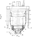
- In this regard, illustrated in Fig. 11 is a prior art rotary atomizing head type coating machine employing an indirect charging system.
- In that figure, indicated at 1 is a coating machine body which is mounted on a reciprocator (not shown). Provided internally of the coating machine body 1 is an
air motor 2 of metallic material consisting of an air bearing 2A and adrive section 2B, along with valve devices (not shown) including a paint valve and a dump valve. Circumferentially, the coating machine body 1 is enshrouded under asynthetic resin cover 3. Theair motor 2 is grounded through acable 2C. The above-mentionedsynthetic resin cover 3 is formed of an insulating synthetic resin material such as polyethylene terephthalate (PET), polyacetal (POM), polyamide (PA), polyethylene (PE), polypropyrene (PP) or the like. - Indicated at 4 is a rotational shaft of metallic material, which is rotatably supported in the air bearing 2A of the
air motor 2. The fore end of therotational shaft 4 is projected out of the coating machine body 1, while its base end is coupled with thedrive section 2B of theair motor 2, thereby driving for high speed rotation. - Denoted at 5 is a bell type rotary atomizing head of metallic material which is provided at the fore end of the
rotational shaft 4, the rotary atomizinghead 5 having a cup-shapedcircumferential surface 5A, an innerpaint smoothing surface 5B and apaint releasing edge 5C. - Indicated at 6 is a center feed type paint supply pipe which is passed internally of the
rotational shaft 4, thepaint supply pipe 6 having its fore end extended into the rotary atomizinghead 5 and connected at its base end to a paint valve which is in communication with a paint tank through a paint pipe (both not shown). - The
reference numeral 7 indicates a shaping air ring which is threaded on a fore end portion of thesynthetic resin cover 3 on the front side of the coating machine body 1. This shapingair ring 7 is located at the fore end of the coating machine body 1 in a position on the rear side of the rotary atomizinghead 5 in such a way as to circumvent the,circumferential surfaces 5A of the atomizinghead 5. - In this instance, the shaping
air ring 7 is constituted by aninner ring 8 which is formed of an insulating synthetic resin material, and anouter ring 9 likewise of an insulating synthetic resin material which is positioned around the outer periphery of theinner ring 8. Formed between the inner and outer rings is anair outlet 10 in the form of an annular gap through which shaping air is spurted out as indicated by arrow A to generate air flows. By attaching theouter ring 9 to thesynthetic resin cover 3, theinner ring 8 can be fixed in position and electrically in contact with theair motor 2. For example, theinner ring 8 andouter ring 9 are formed of insulating synthetic resin material such as polyether sulfone (PES), polyphenylene sulfide (PPS), polyether imide (PEI), polyether ether ketone (PEEK) or the like. - Indicated at 11 are six external electrodes (only two electrodes are shown in the drawings) which are located in equidistant spaced positions, radially outward of the
synthetic resin cover 3 and rearward of thepaint releasing edges 5C of the rotary atomizinghead 5. Theseexternal electrodes 11 are applied with a high voltage (e.g., -60kV to -90kV) from an external high voltage generator (not shown) to charge paint particles to be sprayed from thepaint releasing edges 5C of the above-described rotary atomizinghead 5. - Since the
air motor 2 is grounded through thecable 2C, theair motor 2,rotational shaft 4 and rotary atomizinghead 5, which are all formed of a metallic material, are maintained at the same earth potential. - With a paint coating machine having a rotary atomizing head arranged as described above, upon applying a high voltage to the respective
external electrodes 11, electrostatic fields are formed by electric lines of force between each one of theexternal electrodes 11 and the rotary atomizinghead 5 and at the same time between each one of theexternal electrodes 11 and a coating object (not shown). Besides, under the influence of a high voltage of -60kV to -90kV which is applied to the respectiveexternal electrodes 11, an ionization zone is formed in the vicinity of the fore end of each external electrode. - In this state, the
rotational shaft 4 and rotary atomizinghead 5 are put in high speed rotation by theair motor 2 on the coating machine body 1, and the paint valve is opened to supply a paint to the rotary atomizinghead 5 through thepaint supply pipe 6. The paint which has been fed to the rotary atomizinghead 5 is spread into a thin film-like shape on thepaint smoothing surface 5B under the influence of the centrifugal force resulting from the rotation. The liquid paint film is split into liquid threads as it is thrown radially outward from thepaint releasing edges 5C, and the liquid threads are eventually broken and atomized into fine particle. - In the ionizing zones which are formed forward of the respective external electrodes, atomized paint particles are charged with high voltage, and the resulting charged paint particles are urged to fly toward the coating object which is connected to the ground, and deposit on the surfaces of the coating object.
- Since the rotary atomizing
head 5 is in high speed rotation, paint particles which are thrown out from thepaint releasing edges 5C tend to fly in radially outward directions under the influence of the centrifugal force. However, by the action of shaping air which is spurted out in the direction of arrow A from theair outlet 10, paint particles off thepaint releasing edge 5C of the rotary atomizinghead 5 are shaped into a forwardly converging pattern. - In the case of the coating machine with the rotary atomizing head as described above, the coating machine body 1 is prevented from being contaminated with negatively charged paint particles by covering the machine body 1, except the rotary atomizing
head 5, with an insulating synthetic resin material like the shapingair ring 7 andsynthetic resin cover 3. More specifically, when a high voltage is applied to the respectiveexternal electrodes 11, the component parts of synthetic resin material including the shapingair ring 7 and theresin cover 3 are negatively charged under the influence of negative ions generated by theexternal electrodes 11. Consequently, due to a phenomenon of homopolar repulsions, negative ions charged on the shapingair ring 7 and resincover 3 repel and keep the negatively charged paint particles from depositing on the surfaces of thecover 3 andring 7. - However, actual paint coating operations invariably face a problem of contamination of the shaping
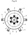
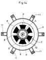
air ring 7, developing gradually after starting a coating operation by applying a high voltage to theexternal electrodes 11 and putting the rotary atomizinghead 5 in high speed rotation, because paint particles P in floating mist deposit on the shapingair ring 7 increasingly with the time of paint coating operation, namely, increasingly as the time of coating operation lapses 5 minutes (Fig. 12), 10 minutes (Fig. 13) and 15 minutes (Fig. 14). - Studying the mechanisms of contamination by charged paint particles, particularly from relations in potential between the rotary atomizing
head 5 and the shapingair ring 7, it is worthwhile to note that the shapingair ring 7 of insulating synthetic resin material is simply held in contact, through that synthetic resin material, with theair motor 2 which is connected to the ground. In contrast, the rotary atomizinghead 5 is directly connected to the ground through therotational shaft 4 andair motor 2 of metallic material. Therefore, looking at the potential relations from the side of theexternal electrodes 11 which are applied with a high negative voltage, the shapingair ring 7 is electrically more closer to the positive side than the rotary atomizinghead 5 which is connected to the ground. - For these reasons, a greater potential difference occurs between the rotary atomizing
head 5 and the respectiveexternal electrodes 11 than between the shapingair ring 7 and the respectiveexternal electrodes 11. Accordingly, it is considered that greater and stronger positive discharges occur at thepaint releasing edges 5C of the rotary atomizinghead 5, while smaller and weaker positive discharges occur at the fore end of the shapingair ring 7. - As a consequence, negative ions generated by the respective
external electrodes 11 are pulled toward the positive discharges as if attracted by the rotary atomizinghead 5 and the shapingair ring 7, and larger and thicker clouds of negative ions occur at thepaint releasing edges 5C while smaller and thinner clouds of negative ions appear at the fore end of the shapingair ring 7. In addition, taking into account the extremely small positive discharges and the existence of blasts of shaping air coming out of the shapingair ring 7, it is presumable that the clouds at the fore end of the shapingair ring 7 are extremely lean. - Under these circumstances, paint particles sprayed from the
paint releasing edges 5C of the rotary atomizinghead 5 are negatively charged while being passage through the ionization zones of theexternal electrodes 11, and the charged paint particles are urged to fly toward and deposit on a coating object which is at the earth potential (with a tendency toward the positive when looked at from the side of the external electrodes 11). However, a part of paint particles are urged to flow in a forward direction from behind the shapingair ring 7 entrained on air vortices generated by rotation of the rotary atomizinghead 5. At this time, negative ions around the fore end of the air shapingring 7 are lessened and leaned out by the occurrence of weak positive discharges as mentioned hereinbefore. Therefore, it is assumed that floating paint particles (paint mist) which have been negatively charged by theexternal electrodes 11 are attracted toward the positive discharges instead of being repelled by negative ions, and deposit on and contaminate fore end portions of the air shapingring 7. - Further, contamination of the shaping
air ring 7 by deposition of the paint P occurs progressively in a pattern as shown in Figs. 12 to 14. As clear from these figures, the shapingair ring 7 undergoes contamination in a more conspicuous degree especially in those areas between the lines (indicated by one-dot chain lines) connecting the center of the rotary atomizinghead 5 with the respectiveexternal electrodes 11. Taking into consideration the positional relations with the sixexternal electrodes 11, the reason for this seems to be that positive discharges occur in a greater degree on the lines connecting the center of the rotary atomizinghead 5 with the respectiveexternal electrodes 11 than between these lines. This can be explained by the fact that the contamination by paint P occurs initially between outer ends of these lines and spread in radially outward directions toward thesynthetic resin cover 3. - In view of the above-discussed problems with the prior art, it is an object of the present invention to provide a rotary atomizing head type coating machine, which can prevent contamination of a shaping air ring of the rotary atomizing head by a paint.
- In accordance with the present invention, for achieving the above-stated objective, there is provided a rotary atomizing head type coating machine basically including a coating machine body circumferentially enshrouded under a synthetic resin cover, an air motor provided within the coating machine body and grounded to the earth potential, a rotary atomizing head provided at the fore end of the coating machine body and coupled with the air motor, the rotary atomizing head being terminated with paint releasing edges at the fore end thereof, a shaping air ring provided at the fore end of the coating machine body in such a way as to circumvent the outer periphery of the rotary atomizing head and having an air outlet to spurt shaping air from behind the paint releasing edges of the rotary atomizing head, and external electrodes positioned radially on the outer side of the coating machine body and externally applied with a high voltage to charge paint particles sprayed from the paint releasing edges of the rotary atomizing head, characterized in that at least part of the shaping air ring is formed of a conductive material and electrically connected to the air motor, and an annular repulsion electrode is formed at least in part of the conductive material.
- With the arrangements just described, the annular repulsion electrode is directly connected to the ground through the air motor, so that stronger positive discharges occur at the annular repulsion electrode than at the paint releasing edges. As a consequence, clouds of negative ions which are generated by the external electrodes are pulled toward stronger positive discharges on the side of the shaping air ring, preventing deposition of paint particles on the air shaping ring by the phenomenon of homopolar repulsions which occur between the negatively charged paint particles and clouds of negative ions.
- In this instance, the shaping air ring may be constituted by an inner ring formed of a conductive material and electrically connected to the air motor, an outer ring formed of an insulating synthetic resin material and positioned in such a way as to enshroud the outer periphery of the inner ring, and an air outlet formed and defined between the inner and outer rings, the above-mentioned annular repulsion electrode being constituted by a fore end portion of the inner ring.
- Alternatively, the air shaping ring may be constituted by a ring body formed of an insulating synthetic resin material and having an air outlet at the fore end thereof, a conductive ring formed on the inner periphery of the shaping air ring by means of a conductive material and electrically connected to the air motor, the above-mentioned annular repulsion electrode being constituted by a fore end portion of the conductive ring.
- Further, the shaping air ring may be constituted by a ring body formed of an insulating synthetic resin material and having an air outlet on a flat front face thereof, a conductive ring formed on the inner periphery of the shaping air ring body by the use of a conductive material and electrically connected to the air motor, and an annular repulsion electrode formed on the front face of the shaping air ring by a separate member from the conductive ring and electrically connected to the conductive ring.
- By arranging the shaping air ring of the present invention in various specific forms as described above, clouds of negative ions pulled toward the annular repulsion electrode can be carried forward toward the outer periphery of the rotary atomizing head by shaping air spurted from the respective air outlets, contributing to facilitate the negative charging of paint particles which are released from the paint releasing edges of the rotary atomizing head.
- Further, a conductive metal may be used as the conductive material which constitutes the above-described annular repulsion electrode.
- Alternatively, a conductive synthetic resin material may be used as the conductive material which constitutes the annular repulsion electrode if desired.
- On the other hand, the shaping air ring according to the present invention may be of an insulating synthetic resin material, and provided with a conductive film layer formed on the inner periphery of the shaping air ring and electrically connected to the air motor, and an annular repulsion electrode constituted by at least part of the conductive film layer.
- In this instance, the shaping air ring may be constituted by an inner ring formed of an insulating synthetic resin material, an outer ring formed of an insulating synthetic resin material and positioned in such a way as to cover the circumference of the inner ring, an air outlet formed between the inner and outer rings, a conductive film layer coated with a conductive paint on the inner periphery of the inner ring, and an annular repulsion electrode constituted by a fore end portion of the conductive film layer.
- In an alternative form, the shaping air ring is constituted by a ring body formed of an insulating synthetic resin material and having air outlets on a flat front face thereof, a conductive film layer coated with a conductive paint on the inner periphery and extended to the flat front face of the shaping air ring body, and an annular repulsion electrode constituted by a fore end portion of the conductive film layer.
- On the other hand, according to the present invention, the above-described annular repulsion electrode can be formed as an annular ring-like body which circumvents circumferential surfaces of the rotary atomizing head in the vicinity thereof.
- In the accompanying drawings:
- Fig. 1 is a vertical section through major components of a rotary atomizing head type coating machine adopted as a first embodiment of the invention;
- Fig. 2 is a schematic front view of the coating machine of the first embodiment, with a rotary atomizing head assembly removed;
- Fig. 3 is a vertical section through major components of a rotary atomizing head type coating machine adopted as a second embodiment of the invention;
- Fig. 4 is a schematic front view of the coating machine of the second embodiment, with a rotary atomizing head assembly removed;
- Fig. 5 is a vertical section through major components of a rotary atomizing head type coating machine adopted as a third embodiment of the invention;
- Fig. 6 is a vertical section through major components of a rotary atomizing head type coating machine adopted as a fourth embodiment of the invention;
- Fig. 7 is a vertical section through major components of a rotary atomizing head type coating machine adopted as a fifth embodiment of the invention;
- Fig. 8 is a vertical section through major components of a rotary atomizing head type coating machine adopted as a sixth embodiment of the invention;
- Fig. 9 is a vertical section through major components of a rotary atomizing head type coating machine adopted as a seventh embodiment of the invention;
- Fig. 10 is a vertical section through major components of a rotary atomizing head type coating machine adopted as an eighth embodiment of the invention;
- Fig. 11 is a vertical sectional view of a prior art rotary atomizing head type coating machine, showing its general construction;
- Fig. 12 is a schematic front view of the coating machine, with its rotary atomizing head assembly removed to show the degree of contamination occurring to its shaping air ring in five minutes of paint coating operation;
- Fig. 13 is a schematic front view of the coating machine, with its rotary atomizing head assembly removed to show the degree of contamination occurring to its shaping air ring in 10 minutes of paint coating operation; and
- Fig. 14 is a schematic front view of the coating machine, with its rotary atomizing head assembly removed to show the degree of contamination occurring to its shaping air ring in 15 minutes of paint coating operation.
- Hereafter, the present invention is described more particularly by way of its preferred embodiments with reference to Figs. 1 through 10. In the following description of preferred embodiments, those component parts which are common with the above-described prior art counterpart are simply designated by common reference numerals or characters without repeating same explanations.
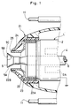
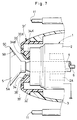
- Referring first to Figs. 1 and 2, there is shown a first embodiment of the present invention.
- In these figures, indicated at 21 is a shaping air ring which is threaded on a fore end portion of a
synthetic resin cover 3 at the fore end of a coating machine body 1 proper. Namely, in place of the shapingair ring 7 of the prior art described hereinbefore, the shapingair ring 21 is provided at the fore end of the coating machine body 1 at a position behind arotary atomizing head 5 in such a manner as to circumvent thecircumferential surfaces 5A of the latter. - In this case, the shaping
air ring 21 is constituted by aninner ring 22 which is formed of a conductive material, for example, a metallic material such as copper, stainless steel, aluminum or the like, anouter ring 23 which is positioned to circumvent the outer periphery of theinner ring 22 and formed of an insulating synthetic resin material such as, for example, polyether sulfone (PES), polyphenylene sulfide (PPS), polyether imide (PEI), polyether ether ketone (PEEK) or the like, and anannular air outlet 24 located at the fore ends of the inner andouter rings 23 to spurt shaping air toward the outer periphery of therotary atomizing head 5. Theinner ring 22 has itsbase end 22A held in contact with and electrically connected to the outer periphery of theair motor 2, which is grounded to the earth. - Denoted at 25 is an annular repulsion electrode which is provided at a
fore end portion 22B of theinner ring 22. Thisannular repulsion electrode 25 is formed in a ring-like form integrally with theinner ring 22 and located closely aroundcircumferential surfaces 5A of therotary atomizing head 5. - In paint coating operations, the rotary atomizing head type coating machine of this embodiment, using the arrangements just described, operates in the same manner as the prior art counterpart described hereinbefore.
- According to this embodiment of the invention, however, the
inner ring 22 of the shapingair ring 21 is formed of a metallic material, and itsbase end 22A can be directly connected to the ground through theair motor 2, forming theannular repulsion electrode 25 at itsfore end 22B. On the other hand, as mentioned hereinbefore in connection with the prior art, therotary atomizing head 5 of a metallic material is also directly grounded to the earth through theair motor 2, so that theannular repulsion electrode 25 of the shapingair ring 21 and therotary atomizing head 5 remain at the same potential (at the earth potential). - Besides, since the
external electrodes 11 are positioned rearward of thepaint releasing edges 5C of therotary atomizing head 5, the distance from theexternal electrodes 11 to theannular repulsion electrode 25 is shorter than the distance from theexternal electrodes 11 to thepaint releasing edges 5C of therotary atomizing head 5. Therefore, positive discharges occur in a greater degree at theannular repulsion electrode 25, which is located closer to theexternal electrodes 11, than at thepaint releasing edge 5C which is more distant from theexternal electrodes 11. As a result, clouds of negative ions generated by the respectiveexternal electrodes 11 are pulled toward theannular repulsion electrode 25 because of the stronger positive discharges, and tend to linger in the vicinity of theannular repulsion electrode 25 in enlarged and thickened state. - Accordingly, paint particles which have been released from the
paint releasing edges 5C of therotary atomizing head 5 and negatively charged by the high voltageexternal electrodes 11, are securely kept from depositing on the shapingair ring 21 by homopolar repulsions occurring between negatively charged paint particles and the clouds of negative ions. - Further, in this case, the shaping
air ring 21 which has theinner ring 22 surrounded by theouter ring 23 of an insulating synthetic resin material can secure a sufficient insulation distance between theinner ring 22 and each one of theexternal electrodes 11, thereby preventing shortcircuiting between theannular repulsion electrode 25 of the shapingair ring 21 and theexternal electrodes 11, and guaranteeing high safety by suppressing positive discharges at theannular repulsion electrode 25. - Furthermore, along with shaping air which is spurted out from the
air outlet hole 24 of the shapingair ring 21, a large quantity of negative ions which have been pulled toward and around theannular repulsion electrode 25 can be carried forward toward the outer periphery of therotary atomizing head 5. Accordingly, paint particles released from thepaint releasing edges 5C of therotary atomizing head 5 can be effectively charged by the forwardly carried negative ions in such a manner as to enhance the paint deposition efficiency on a coating object. - As described above, the shaping
air ring 21 of this embodiment uses theinner ring 22 of metallic material, forming theannular repulsion electrode 25 at the fore end thereof. Theannular repulsion electrode 25 which is located at the fore end of the shapingair ring 21 is capable of inducing strong positive discharges to attract clouds of negative ions thereto, so that mist of paint particles is securely prevented from depositing on the shapingair ring 21 andresin cover 3 by homopolar repulsions occurring between negative ion clouds and negatively charged paint particles. - Referring now to Figs. 3 and 4, there is shown a second embodiment of the present invention, which is characterized in that the shaping air ring is constituted by a single ring structure and provided with a plural number of air outlet holes at its fore end, and in that an annular repulsion electrode is formed at the fore end of a conductive ring which is fitted on the inner periphery of the shaping air ring. In the following description of the second embodiment, those component parts which are common with the foregoing first embodiment are simply designated by common reference numerals or characters without repeating same explanations.
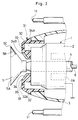
- In these figures, indicated at 31 is a shaping air ring which is employed in this embodiment in place of the shaping
air ring 21 of the first embodiment. The shapingair ring 31 is mounted in position at the fore end of the coating machine body 1, in threaded engagement with a fore end portion of thesynthetic resin cover 3 at the fore end of the coating machine body 1 in such a manner as to circumventcircumferential surfaces 5A at a position rearward of therotary atomizing head 5. - The shaping
air ring 31 includes aring body 32 substantially of J-shape in section with a flatfront face 32A, which is formed of an insulating synthetic resin material such as, for example, polyether sulfone (PES), polyphenylene sulfide (PPS), polyether imide (PEI), polyether ether ketone (PEEK) or the like, and a plural number of air outlet holes 33 which are arranged circularly on the flatfront face 32A of thering body 32 to spurt shaping air toward the outer periphery of therotary atomizing head 5. - Indicated at 34 is a conductive ring which is integrally cast on the inner periphery of the
ring body 32 by the use of a metallic conductive material such as copper, stainless steel, aluminum or the like. Theconductive ring 34 has its base end 34A electrically conductively in contact with the outer periphery of theair motor 2, and has itsfore end 34B extended up to thefront end face 32A of the shapingair ring 31. - Denoted at 35 is an annular repulsion electrode which is provided in a
fore end portion 34B of theconductive ring 34 of the shapingair ring 31, theannular repulsion electrode 35 being formed integrally with theconductive ring 34 in such a way as to circumvent thecircumferential surfaces 5A of therotary atomizing head 5 in the vicinity thereof. - According to the present embodiment with the arrangements just described, the shaping
air ring 31 on the rotary atomizing head type coating machine induces stronger positive discharges at theannular repulsion electrode 35 than at thepaint releasing edges 5C of therotary atomizing head 5, substantially in the same manner as in the foregoing first embodiment. As a consequence, clouds of negative ions are enlarged and thickened as they are pulled toward the positive discharges at theannular repulsion electrode 35, preventing deposition of charged paint particles on the shapingair ring 31 by homopolar repulsions between clouds of negative ions and negatively charged paint particles. - Further, by shaping air which is spurted out through the shaping
air outlets 33, clouds of negative ions are moved forward toward the outer periphery of therotary atomizing head 5 to charge of atomized paint particles and therefore to enhancement of the paint deposition efficiency on a coating object. - Illustrated in Fig. 5 is a third embodiment of the invention, which is characterized in that the shaping air ring is constituted by a single integral ring structure with air outlet holes on a front face thereof, a conductive ring is provided on the inner periphery of the shaping air ring, and an annular repulsion electrode is provided on the front face by fixing thereon a separate member which is electrically connected to the conductive ring. In the following description of the third embodiment, those component parts common with the foregoing first embodiment are simply designated by common reference numerals or characters without repeating similar explanations.
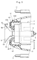
- In that figure, indicated at 41 is the shaping air ring which is used in the third embodiment. This shaping
air ring 41 is constituted by aring body 42 substantially of a J-shape in section having a flatfront face 42A, which is formed of an insulating synthetic resin material similar to that of the shapingair ring 31 of the second embodiment, and a plural number of air outlet holes 43 which are arranged circularly on thefront face 42A for spurting shaping air toward circumferential surfaces of therotary atomizing head 5. - Denoted at 44 is a conductive ring which is integrally cast on the inner periphery of the
ring body 42 by the use of a metallic conductive material such as, for example, copper, stainless steel, aluminum or the like. Theconductive ring 44 has itsbase end 44A held in contact with the outer periphery of theair motor 2 for electrical conduction therethrough. - Indicated at 45 is an annular repulsion electrode which is constituted by a member separate from the
conductive ring 44 and fixed on thefront face 42A of thering body 42. Thisannular repulsion electrode 45 is in the form of a flat ring-like plate and located to circumvent thecircumferential surfaces 5A of therotary atomizing head 5 in the vicinity thereof. Further, theannular repulsion electrode 45 is connected to afore end portion 44B of theconductive ring 44, that is to say, connected through theconductive ring 44 to theair motor 2 which is maintained at the earth potential. - According to the present embodiment with the arrangements just described, the shaping
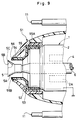
air ring 41 can produce the same operational effects as the counterpart in the foregoing second embodiment. Besides, since theannular repulsion electrode 45 is more positively provided on thefront face 42A of thering body 42 electrically in contact with theconductive ring 44, theannular repulsion electrode 45 has a broader surface area which is capable of generating stronger positive discharges for the purpose of suppressing deposition of paint particles on the shapingair ring 41 all the more. - On the other hand, shown in Figs. 6 to 8 are fourth, fifth and sixth embodiments of the present invention. In the following descriptions of the fourth to sixth embodiments, those components which have corresponding counterparts in the foregoing first to third embodiments are designated by corresponding reference numerals or characters each attached with an apostrophe (').
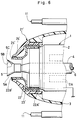
- The fourth embodiment shown in Fig. 6 uses a shaping air ring 21' which is formed with an inner ring 22' of a conductive synthetic resin material in place of the
inner ring 22 of the shapingair ring 21 in the above-described first embodiment. The inner ring 22' has itsbase end 22A' held in contact with and electrically connected to the outer periphery of theair motor 2, while forming an annular repulsion electrode 25' at itsfore end portion 22B'. - In this instance, instead of a metallic material, the inner ring 22' is formed of a conductive synthetic resin material which is imparted with conductivity by mixing metal fiber or powder into a synthetic resin material of the sort as mentioned hereinbefore.
- The fifth embodiment shown in Fig. 7 uses a shaping air ring 31' with a conductive ring 34' of a conductive synthetic resin material in place of the metallic
conductive ring 34 provided on the shapingair ring 31 of the foregoing second embodiment. - Further, the sixth embodiment shown in Fig. 8 uses a shaping air ring 41' with a
conductive ring 44 of a conductive synthetic resin material in place of the metallicconductive ring 44 provided on theair shaping ring 41 of the foregoing third embodiment. - According to the fourth to sixth embodiments with the arrangements just described, the shaping air rings 21', 31' and 41' can produce substantially the same operational effects as in the foregoing first to third embodiments. In addition, the shaping air rings 21', 31' and 41' which are constituted by a molded structure of a mixture of insulating and conductive synthetic resin materials can contribute to enhance the production efficiency, in other words, to reduce the production cost as compared with the shaping air rings in the first to third embodiments.
- Referring now to Fig. 9, there is shown a seventh embodiment of the invention, which is characterized in that the shaping air ring is constituted by a single member and provided with an annular repulsion electrode at the fore end of a conductive film layer formed on the inner periphery of the shaping air ring. In the following description of the seventh embodiment, those component parts common with the first embodiment are designated simply by common reference numerals or characters without repeating similar explanations.
- In this figure, indicated at 51 is the shaping air ring constituted by an
inner ring 52 which is formed of an insulating synthetic resin material similarly to the prior art shapingair ring 7 described hereinbefore, anouter ring 53 similarly formed of an insulating synthetic resin material in such a shape as to enshroud the outer periphery of theinner ring 52, and anannular air outlet 54 formed between the fore ends of the inner andouter rings rotary atomizing head 5. - Denoted at 55 is a conductive film layer which is formed substantially fully around the inner periphery of the
inner ring 52, for example, by application of a conductive paint or the like, and which has itsbase end portion 55A held in contact with and electrically connected to the outer periphery of theair motor 2.Fore end portion 55B of theconductive film layer 55 is extended onto the front end face of theinner ring 52 up to a point near theair outlet 54. As for theconductive film layer 55, there may be used, for example, a conductive paint kneaded with copper powder, aluminum powder, carbon, metal oxide or the like. - Indicated at 56 is an annular repulsion electrode which is provided at a
fore end portion 55B of the above-describedconductive film layer 55. Theannular repulsion electrode 56 is formed integrally with theconductive film layer 55 in such a way as to circumvent thecircumferential surfaces 5A of therotary atomizing head 5 in the vicinity thereof. - This embodiment which is arranged in the manner just described can also produce substantially the same operational effects as in the foregoing embodiments in that negatively charged paint particles are securely prevented from depositing on the shaping
air ring 51 by the phenomenon of homopolar repulsions of negative ion clouds occurring in the vicinity of theannular repulsion electrode 55. - Besides, by shaping air which is spurted out from the
air outlet 54 of the shapingair ring 51, a large quantity of negative ions sucked inward toward the vicinity of theannular repulsion electrode 56, can be carried forward toward the outer periphery of therotary atomizing head 5. Accordingly, paint particles released from therotary atomizing head 5 are charged in a steady and assured manner by forwardly carried negative ions to enhance the paint deposition efficiency on a coating object. - Besides, according to the present embodiment, using the
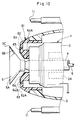
conductive film layer 55 which can be formed by coating a conductive paint on theinner ring 52, the film coating process as well as the fabrication process can be simplified, coupled with an advantage that electrical conductivity or resistance can be set at an arbitrary value according to the film thickness. - Shown in Fig. 10 is an eighth embodiment of the invention, which is characterized in that the shaping air ring is constituted by a single member, with a plural number of air outlets at its fore end, and in that an annular repulsion electrode is constituted by a fore end portion of a conductive film layer formed on its inner periphery. In the following description of the eighth embodiment, those component parts common with the foregoing first embodiment are simply designated by common reference numerals or characters without repeating similar explanations.
- In this figure, indicated at 61 is the shaping air ring which is used in this embodiment. This shaping
air ring 61 is threaded into asynthetic resin cover 3 at the fore end of the paint coating machine body 1, and located in a position behind therotary atomizing head 5 in such a manner as to circumventcircumferential surfaces 5A of therotary atomizing head 5. - In this instance, the shaping
air ring 61 is constituted by a ring body proper 62 which is formed of an insulating synthetic resin material substantially in a J-shape in section with afront face 62A similarly to the counterparts in the foregoing embodiments, and a plural number of air outlet holes 63 which are arranged circularly on thefront face 62A of thering body 62 to spurt shaping air in a forward direction toward the outer periphery of therotary atomizing head 5. - Indicated at 64 is a conductive film layer which is formed substantially fully around the inner periphery of the
ring body 62, for example, by coating thereon a conductive paint or the like. Theconductive film layer 64 is held in contact with and electrically connected with to outer periphery of theair motor 3 at itsbase end 64A, and has itsfore end 64B extended forward as far as thefront face 62A of thering body 62. - Denoted at 65 is an annular repulsion electrode which is provided in a
fore end portion 64B of theconductive film layer 64. Thisannular repulsion electrode 65 is formed integrally with theconductive film layer 64 as a ring-like body which circumvents thecircumferential surfaces 5A of therotary atomizing head 5 in the vicinity thereof. - With the arrangements just described, the present embodiment can also produce substantially the same operational effects as in each one of the foregoing embodiments of the present invention.
- As described in detail hereinbefore, according to the present invention, at least part of the shaping air ring is formed of a conductive material to provide an annular repulsion electrode at least in part of the conductive material. By the provision of the annular repulsion electrode, positive discharges occur more strongly on the side of the annular repulsion electrode than on the side of the paint releasing edges. Clouds of negative ions generated by the external electrodes are therefore pulled toward the stronger positive discharges on the side of the shaping air ring, giving rise to the phenomenon of homopolar repulsion between negatively charged paint particles and clouds of negative ions, thereby preventing contamination of the shaping air ring by paint deposition in an assured manner.
- In one particular form of the present invention, the shaping air ring is constituted by an inner ring formed of a conductive material and electrically connected to the air motor, an outer ring of an insulating synthetic resin material located to enshroud the outer periphery of the inner ring, an air outlet formed between the inner and outer rings, and an annular repulsion ring constituted by a fore end portion of the inner ring. In another form of the present invention, the shaping air ring is constituted by a ring body of an insulating synthetic resin material having an air outlets at the fore end thereof, a conductive ring of a conductive material provided on the inner periphery of the shaping air ring and electrically connected to the air motor, and an annular repulsion electrode constituted by a fore end portion of the conductive ring. As a result, in addition to the prevention of contamination of the shaping air ring, clouds of negative ions pulled toward the annular repulsion electrode are carried forward toward the outer periphery of the rotary atomizing head to charge to negative paint particles which are released from the paint releasing edges of the rotary atomizing head and therefore to enhancement of paint deposition efficiency on a coating object.
- Further, according to the present invention, the shaping air ring may be constituted by a ring body of an insulating synthetic resin material having an air outlets on a flat front face thereof, a conductive ring of conductive material formed on the inner periphery of the shaping air ring and electrically connected to the air motor, and an annular repulsion electrode formed on the front face of the shaping air ring by a separate member from said conductive ring and electrically connected to the conductive ring. In this case, the annular repulsion electrode is provided with a broader surface area and capable of generating strong plasma discharges, thereby suppressing paint deposition on the air shaping ring all the more.
- Furthermore, the annular repulsion electrode according to the present invention can be formed of either a conductive metallic material or a conductive synthetic resin material, so that a grater variety of materials can be used in the fabrication processes from the standpoint of attaining a higher production efficiency.
- Alternatively, according to the present invention, the shaping air ring can be constituted by a ring body of an insulating synthetic resin material, a conductive film layer formed on the shaping air ring and electrically connected to the air motor, and an annular repulsion electrode constituted by at least part of the conductive film layer. In this case, in addition to the operational effects of preventing paint deposition on the shaping air ring by homopolar repulsions between negatively charged paint particles and clouds of negative ions occurring in the vicinity of the annular repulsion electrode, the use of the conductive film layer as an annular repulsion electrode contributes to facilitate the fabrication process of the shaping air ring.
- Further, the use of the conductive film layer which can be formed simply by application of a conductive paint, makes easier the film forming process as well as the shaping air ring fabrication process, in addition to the advantage that the electrical conductivity or resistance of the film layer can be set at an arbitrary value according to the film thickness.
- Furthermore, according to the present invention, the annular repulsion electrode which is provided as an annular ring-like body which circumvents circumferential surfaces of the rotary atomizing head at a position in the ambience of the latter, contributes to uniform and accelerated charging of paint particles which are released from the paint releasing edges of the rotary atomizing head.
Claims (10)
- A rotary atomizing head type coating machine, including a coating machine body circumferentially enshrouded under a synthetic resin cover, an air motor provided within said coating machine body and grounded to the earth potential, a rotary atomizing head provided at the fore end of said coating machine body and coupled with said air motor, said rotary atomizing head being terminated with paint releasing edges at the fore end thereof, a shaping air ring provided at the fore end of said coating machine body in such a way as to circumvent the outer periphery of said rotary atomizing head and having an air outlet to spurt shaping air from behind said paint releasing edges of said rotary atomizing head, and external electrodes positioned radially on the outer side of said coating machine body and externally applied with a high voltage to charge paint particles sprayed from said paint releasing edges of said rotary atomizing head, characterized in that:at least part of said shaping air ring is formed of a conductive material and electrically connected to said air motor, and an annular repulsion electrode is formed at least in part of said conductive material.
- A rotary atomizing head type coating machine as defined in claim 1, wherein said shaping air ring is constituted by an inner ring formed of a conductive material and electrically connected to said air motor, an outer ring formed of an insulating synthetic resin material and positioned in such a way as to enshroud the outer periphery of said inner ring, and an air outlet formed between said inner and outer rings, and said annular repulsion electrode is constituted by a fore end portion of said inner ring.
- A rotary atomizing head type coating machine as defined in claim 1, wherein said shaping air ring is constituted by a ring body formed of an insulating synthetic resin material and having an air outlet at the fore end thereof, a conductive ring formed on the inner periphery of said shaping air ring by the use of a conductive material and electrically connected to said air motor, and said annular repulsion electrode is constituted by a fore end portion of said conductive ring.
- A rotary atomizing head type coating machine as defined in claim 1, wherein said shaping air ring is constituted by a ring body formed of an insulating synthetic resin material and having an air outlet on a flat front face thereof, a conductive ring formed on the inner periphery of said shaping air ring body by the use of a conductive material and electrically connected to said air motor, and an annular repulsion electrode formed on the front face of said shaping air ring by a separate member from said conductive ring and electrically connected to said conductive ring.
- A rotary atomizing head type coating machine as defined in any one of claims 1 to 4, wherein said conductive material constituting said annular repulsion electrode is a conductive metallic material.
- A rotary atomizing head type coating machine as defined in any one of claims 1 to 4, wherein said conductive material constituting said annular repulsion electrode is a conductive synthetic resin material.
- A rotary atomizing head type coating machine, including a coating machine body circumferentially enshrouded under a synthetic resin cover, an air motor provided within said coating machine body and grounded to the earth potential, a rotary atomizing head provided at the fore end of said coating machine body and coupled with said air motor, said rotary atomizing head being terminated with paint releasing edges at the fore end thereof, a shaping air ring provided at the fore end of said coating machine body in such a way as to circumvent the outer periphery of said rotary atomizing head and having an air outlet to spurt shaping air from behind said paint releasing edges of said rotary atomizing head, and external electrodes positioned radially on the outer side of said coating machine body and externally applied with a high voltage to charge paint particles sprayed from said paint releasing edges of said rotary atomizing head, characterized in that:said shaping air ring is formed of an insulating synthetic resin material, and provided with a conductive film layer formed on the inner periphery thereof and electrically connected to said air motor and an annular repulsion electrode constituted by at least part of said conductive film layer.
- A rotary atomizing head type coating machine as defined in claim 7, wherein said shaping air ring is constituted by an inner ring formed of an insulating synthetic resin material, an outer ring formed of an insulating synthetic resin material and positioned in such a way as to circumvent the outer periphery of said inner ring, an air outlet formed between said inner and outer rings, a conductive film layer coated with a conductive paint on the inner periphery of said inner ring, and an annular repulsion electrode constituted by a fore end portion of said conductive film layer.
- A rotary atomizing head type coating machine as defined in claim 7, wherein said shaping air ring is constituted by a ring body formed of an insulating synthetic resin material and having air outlets on a flat front face thereof, a conductive film layer coated with a conductive paint on the inner periphery and extended to said flat front face of said shaping air ring body, and an annular repulsion electrode constituted by a fore end portion of said conductive film layer.
- A rotary atomizing head type coating machine as defined in any one of claims 1 to 9, wherein said annular repulsion electrode is in the form of an annular ring-like body circumventing circumferential surfaces of said rotary atomizing head in the vicinity thereof.
Applications Claiming Priority (7)
| Application Number | Priority Date | Filing Date | Title |
|---|---|---|---|
| JP10684095 | 1995-04-06 | ||
| JP10684195 | 1995-04-06 | ||
| JP10684095 | 1995-04-06 | ||
| JP10684195 | 1995-04-06 | ||
| JP106840/95 | 1995-04-06 | ||
| JP106841/95 | 1995-04-06 | ||
| PCT/JP1996/000929 WO1996031286A1 (en) | 1995-04-06 | 1996-04-05 | Rotary atomizing head type painting device |
Publications (3)
| Publication Number | Publication Date |
|---|---|
| EP0767005A1 true EP0767005A1 (en) | 1997-04-09 |
| EP0767005A4 EP0767005A4 (en) | 1998-02-04 |
| EP0767005B1 EP0767005B1 (en) | 2002-12-18 |
Family
ID=26446946
Family Applications (1)
| Application Number | Title | Priority Date | Filing Date |
|---|---|---|---|
| EP96908347A Expired - Lifetime EP0767005B1 (en) | 1995-04-06 | 1996-04-05 | Rotary atomizing head type coating machine |
Country Status (8)
| Country | Link |
|---|---|
| US (1) | US5775598A (en) |
| EP (1) | EP0767005B1 (en) |
| JP (1) | JP3184455B2 (en) |
| KR (1) | KR100204972B1 (en) |
| CA (1) | CA2192164C (en) |
| DE (1) | DE69625435T2 (en) |
| ES (1) | ES2188744T3 (en) |
| WO (1) | WO1996031286A1 (en) |
Cited By (20)
| Publication number | Priority date | Publication date | Assignee | Title |
|---|---|---|---|---|
| DE19909369A1 (en) * | 1999-03-03 | 2000-09-21 | Daimler Chrysler Ag | Electrostatic atomizer with housing has area of housing facing bell-shaped disc or part (air guidance ring) connected to housing with at least one earthed collection electrode |
| EP1295648A1 (en) * | 2000-06-26 | 2003-03-26 | Abb K.K. | Two-tone coating method |
| US6896735B2 (en) | 2002-01-24 | 2005-05-24 | Behr Systems, Inc. | Integrated charge ring |
| US6972052B2 (en) | 2002-08-28 | 2005-12-06 | Behr Systems, Inc. | Rotational atomizer with external heating system |
| US6986366B2 (en) | 2002-08-28 | 2006-01-17 | Dürr Systems, Inc. | Tube for the electrostatic coating of workpieces |
| US6991178B2 (en) | 2003-01-24 | 2006-01-31 | Dürr Systems, Inc. | Concentric paint atomizer shaping air rings |
| US7018679B2 (en) | 2001-03-29 | 2006-03-28 | Dürr Systems, Inc. | Coating installation with an atomizer change station |
| US7036750B2 (en) | 2002-07-22 | 2006-05-02 | Dürr Systems, Inc. | Axial shaping air design for paint atomizer |
| US7051950B2 (en) | 2001-03-29 | 2006-05-30 | Dürr Systems, Inc. | Atomizer for coating unit and method for its material supply |
| US7156795B2 (en) | 2001-03-29 | 2007-01-02 | Dürr Systems, Inc. | Tool change system for a machine |
| EP1832348A1 (en) * | 2004-12-28 | 2007-09-12 | Ransburg Industrial Finishing KK | Electrostatic coater |
| US7275702B2 (en) | 2001-03-29 | 2007-10-02 | Durr Systems, Inc. | Valve unit for an electrostatic coating installation |
| US7347649B2 (en) | 2002-07-11 | 2008-03-25 | Durr Systems, Inc. | Powder purge tube |
| EP1911521A1 (en) * | 2005-08-01 | 2008-04-16 | Abb K.K. | Electrostatic coating device |
| US7432495B2 (en) | 2002-09-02 | 2008-10-07 | Durr Systems, Inc. | Sensor arrangement for a coating system |
| US7478763B2 (en) | 2003-05-05 | 2009-01-20 | Itw Gema Gmbh | Spray coating device for spraying coating material, in particular coating powder |
| WO2009040684A1 (en) * | 2007-09-28 | 2009-04-02 | Officine Meccaniche Pejrani S.R.L. | A method and apparatus for disinfecting enclosed spaces |
| CN102500485A (en) * | 2011-11-17 | 2012-06-20 | 中冶京诚工程技术有限公司 | Annular discharging nozzle |
| US8671495B2 (en) | 2006-11-06 | 2014-03-18 | Durr Systems, Inc. | Scraper pig |
| US10773265B2 (en) | 2015-01-21 | 2020-09-15 | Dürr Systems Ag | Bell cup or atomizer ring comprising an insulating coating |
Families Citing this family (14)
| Publication number | Priority date | Publication date | Assignee | Title |
|---|---|---|---|---|
| DE69717416T2 (en) * | 1996-10-01 | 2003-04-03 | Alstom Power Kk | rotary atomizing |
| CA2322256C (en) * | 1998-03-04 | 2006-09-05 | Abb Patent Gmbh | High voltage source rotary spray |
| EP1177050B1 (en) * | 1999-03-16 | 2003-01-22 | ABB PATENT GmbH | High-speed rotary atomizer with an air guide ring |
| FR2796573A1 (en) | 1999-07-22 | 2001-01-26 | Sames Sa | Rotary atomising head e.g. for coating motor vehicle bodies has at least part of housing covered with an insulating material |
| US7721976B2 (en) * | 2002-07-22 | 2010-05-25 | Durr Systems, Inc. | High speed rotating atomizer assembly |
| JP4445830B2 (en) * | 2004-10-14 | 2010-04-07 | ランズバーグ・インダストリー株式会社 | Electrostatic sprayer |
| JP4612030B2 (en) * | 2005-08-01 | 2011-01-12 | Abb株式会社 | Electrostatic coating equipment |
| JP4769762B2 (en) | 2007-05-18 | 2011-09-07 | トヨタ自動車株式会社 | Anti-stain cover for coating machines |
| DE102009013979A1 (en) * | 2009-03-19 | 2010-09-23 | Dürr Systems GmbH | Electrode arrangement for an electrostatic atomizer |
| KR101226587B1 (en) * | 2009-05-11 | 2013-01-28 | 에이비비 가부시키가이샤 | Electrostatic coating device |
| DE102011006617B4 (en) | 2011-04-01 | 2018-08-16 | Bayerische Motoren Werke Aktiengesellschaft | Rotary atomizer with external electrodes for coating a workpiece |
| FR3012985B1 (en) * | 2013-11-12 | 2016-12-09 | Sames Tech | ELECTROSTATIC COATING PRODUCT PROJECTOR AND PROJECTION INSTALLATION COMPRISING SUCH A PROJECTOR |
| CN108136420B (en) | 2016-02-19 | 2020-05-22 | Abb瑞士股份有限公司 | Electrostatic coater |
| EP3593906B1 (en) | 2017-08-18 | 2024-03-20 | ABB Schweiz AG | Electrostatic coating machine |
Family Cites Families (21)
| Publication number | Priority date | Publication date | Assignee | Title |
|---|---|---|---|---|
| US2784114A (en) * | 1951-11-26 | 1957-03-05 | Ransburg Electro Coating Corp | Spray coating apparatus and method |
| US2955565A (en) * | 1956-03-19 | 1960-10-11 | Electro Dispersion Corp | Electrostatic coating apparatus |
| US3021077A (en) * | 1956-03-20 | 1962-02-13 | Ransburg Electro Coating Corp | Electrostatic coating apparatus |
| US3010428A (en) * | 1957-09-10 | 1961-11-28 | Interplanetary Res & Dev Corp | Spraying devices |
| FR1110350A (en) * | 1959-03-31 | 1956-02-10 | Sames Mach Electrostat | Apparatus for electrostatic spraying and projection |
| NL251152A (en) * | 1959-05-20 | |||
| US3009441A (en) * | 1959-06-18 | 1961-11-21 | Ransburg Electro Coating Corp | Apparatus for electrostatically spray coating |
| US3083121A (en) * | 1959-09-10 | 1963-03-26 | Ransburg Electro Coating Corp | Shunt control to prevent arcing in an electrostatic spray coating system and method |
| BE618356A (en) * | 1961-05-31 | 1962-11-30 | ||
| FR1330178A (en) * | 1962-04-25 | 1963-06-21 | Sames Mach Electrostat | Improvements to electrostatic spray heads |
| SE358819B (en) * | 1967-10-11 | 1973-08-13 | Greiff Svenska Maskin Ab | |
| US3826425A (en) * | 1972-06-21 | 1974-07-30 | Ransburg Corp | Electrostatic apparatus |
| JPS5534130A (en) * | 1978-08-31 | 1980-03-10 | Nippon Ranzubaagu Kk | Electrostatic coating machine |
| US4228961A (en) * | 1979-05-07 | 1980-10-21 | Onoda Cement Co., Ltd. | Electrostatic power painting head |
| DE3429075A1 (en) * | 1984-08-07 | 1986-02-20 | Hermann Behr & Sohn Gmbh & Co, 7121 Ingersheim | Device for the electrostatic coating of articles |
| US4887770A (en) * | 1986-04-18 | 1989-12-19 | Nordson Corporation | Electrostatic rotary atomizing liquid spray coating apparatus |
| JPH06134353A (en) * | 1992-10-23 | 1994-05-17 | Ransburg Automot Kk | Electrostatic coater |
| US5474236A (en) * | 1992-12-03 | 1995-12-12 | Nordson Corporation | Transfer of electrostatic charge to a rotary atomizer head through the housing of a rotary atomizing spray device |
| US5433387A (en) * | 1992-12-03 | 1995-07-18 | Ransburg Corporation | Nonincendive rotary atomizer |
| DE4340441A1 (en) * | 1992-12-03 | 1994-06-09 | Nordson Corp | Rotating atomiser for coating with paint - has hollow drive shaft for spray head with feed pipe inside and electrostatic charge applied |
| JPH06320065A (en) * | 1993-05-07 | 1994-11-22 | Toyota Motor Corp | Bell-shaped electrostatic coater |
-
1996
- 1996-04-05 EP EP96908347A patent/EP0767005B1/en not_active Expired - Lifetime
- 1996-04-05 DE DE69625435T patent/DE69625435T2/en not_active Expired - Lifetime
- 1996-04-05 ES ES96908347T patent/ES2188744T3/en not_active Expired - Lifetime
- 1996-04-05 CA CA002192164A patent/CA2192164C/en not_active Expired - Fee Related
- 1996-04-05 KR KR1019960706711A patent/KR100204972B1/en not_active IP Right Cessation
- 1996-04-05 JP JP11010796A patent/JP3184455B2/en not_active Expired - Fee Related
- 1996-04-05 US US08/737,934 patent/US5775598A/en not_active Expired - Lifetime
- 1996-04-05 WO PCT/JP1996/000929 patent/WO1996031286A1/en active IP Right Grant
Non-Patent Citations (2)
| Title |
|---|
| No further relevant documents disclosed * |
| See also references of WO9631286A1 * |
Cited By (28)
| Publication number | Priority date | Publication date | Assignee | Title |
|---|---|---|---|---|
| DE19909369A1 (en) * | 1999-03-03 | 2000-09-21 | Daimler Chrysler Ag | Electrostatic atomizer with housing has area of housing facing bell-shaped disc or part (air guidance ring) connected to housing with at least one earthed collection electrode |
| EP1295648A4 (en) * | 2000-06-26 | 2006-06-14 | Abb Kk | Two-tone coating method |
| EP1295648A1 (en) * | 2000-06-26 | 2003-03-26 | Abb K.K. | Two-tone coating method |
| US7275702B2 (en) | 2001-03-29 | 2007-10-02 | Durr Systems, Inc. | Valve unit for an electrostatic coating installation |
| US7051950B2 (en) | 2001-03-29 | 2006-05-30 | Dürr Systems, Inc. | Atomizer for coating unit and method for its material supply |
| US7018679B2 (en) | 2001-03-29 | 2006-03-28 | Dürr Systems, Inc. | Coating installation with an atomizer change station |
| US7156795B2 (en) | 2001-03-29 | 2007-01-02 | Dürr Systems, Inc. | Tool change system for a machine |
| US6896735B2 (en) | 2002-01-24 | 2005-05-24 | Behr Systems, Inc. | Integrated charge ring |
| US7347649B2 (en) | 2002-07-11 | 2008-03-25 | Durr Systems, Inc. | Powder purge tube |
| US7036750B2 (en) | 2002-07-22 | 2006-05-02 | Dürr Systems, Inc. | Axial shaping air design for paint atomizer |
| US6972052B2 (en) | 2002-08-28 | 2005-12-06 | Behr Systems, Inc. | Rotational atomizer with external heating system |
| US6986366B2 (en) | 2002-08-28 | 2006-01-17 | Dürr Systems, Inc. | Tube for the electrostatic coating of workpieces |
| US7432495B2 (en) | 2002-09-02 | 2008-10-07 | Durr Systems, Inc. | Sensor arrangement for a coating system |
| US6991178B2 (en) | 2003-01-24 | 2006-01-31 | Dürr Systems, Inc. | Concentric paint atomizer shaping air rings |
| US7478763B2 (en) | 2003-05-05 | 2009-01-20 | Itw Gema Gmbh | Spray coating device for spraying coating material, in particular coating powder |
| EP1832348A1 (en) * | 2004-12-28 | 2007-09-12 | Ransburg Industrial Finishing KK | Electrostatic coater |
| EP1832348A4 (en) * | 2004-12-28 | 2008-11-05 | Ransburg Ind Finishing Kk | Electrostatic coater |
| US7784718B2 (en) | 2004-12-28 | 2010-08-31 | Ransburg Industrial Finishing K.K. | Electrostatic paint sprayer |
| EP1911521A1 (en) * | 2005-08-01 | 2008-04-16 | Abb K.K. | Electrostatic coating device |
| EP2055389A3 (en) * | 2005-08-01 | 2009-07-15 | Abb K.K. | Electrostatic coating apparatus |
| EP1911521A4 (en) * | 2005-08-01 | 2008-11-12 | Abb Kk | Electrostatic coating device |
| US8671495B2 (en) | 2006-11-06 | 2014-03-18 | Durr Systems, Inc. | Scraper pig |
| WO2009040684A1 (en) * | 2007-09-28 | 2009-04-02 | Officine Meccaniche Pejrani S.R.L. | A method and apparatus for disinfecting enclosed spaces |
| GB2465536A (en) * | 2007-09-28 | 2010-05-26 | Mecanniche Pejrani S R L Off | A method and apparatus for disinfecting enclosed spaces |
| GB2465536B (en) * | 2007-09-28 | 2011-09-28 | Mecanniche Pejrani S R L Off | A method and apparatus for disinfecting enclosed spaces |
| US8529833B2 (en) | 2007-09-28 | 2013-09-10 | Officine Meccaniche Perjrani S.r.l. | Method and apparatus for disinfecting enclosed spaces |
| CN102500485A (en) * | 2011-11-17 | 2012-06-20 | 中冶京诚工程技术有限公司 | Annular discharging nozzle |
| US10773265B2 (en) | 2015-01-21 | 2020-09-15 | Dürr Systems Ag | Bell cup or atomizer ring comprising an insulating coating |
Also Published As
| Publication number | Publication date |
|---|---|
| JPH08332418A (en) | 1996-12-17 |
| KR970703203A (en) | 1997-07-03 |
| US5775598A (en) | 1998-07-07 |
| WO1996031286A1 (en) | 1996-10-10 |
| CA2192164A1 (en) | 1996-10-10 |
| JP3184455B2 (en) | 2001-07-09 |
| EP0767005A4 (en) | 1998-02-04 |
| KR100204972B1 (en) | 1999-06-15 |
| EP0767005B1 (en) | 2002-12-18 |
| CA2192164C (en) | 1999-10-05 |
| DE69625435D1 (en) | 2003-01-30 |
| ES2188744T3 (en) | 2003-07-01 |
| DE69625435T2 (en) | 2003-10-23 |
Similar Documents
| Publication | Publication Date | Title |
|---|---|---|
| EP0767005B1 (en) | Rotary atomizing head type coating machine | |
| US7128277B2 (en) | Powder bell with secondary charging electrode | |
| JP4612048B2 (en) | Electrostatic coating equipment | |
| JPWO2010131541A1 (en) | Electrostatic coating equipment | |
| US8096264B2 (en) | Repulsion ring | |
| US20060081729A1 (en) | Electrostatic spraying apparatus | |
| EP1038588A1 (en) | Rotary atomizing head type coating device | |
| US9901941B2 (en) | Electrostatic spray device for spraying a liquid coating product, and spray facility comprising such a spray device | |
| EP3417946B1 (en) | Electrostatic coater | |
| US4225090A (en) | Device for painting by electrostatic powder spraying | |
| US6276618B1 (en) | Electrostatic powder spray gun | |
| US6676049B2 (en) | Bell cup powder spray applicator | |
| US6889921B2 (en) | Bell cup skirt | |
| US11154883B2 (en) | Electrostatic coating machine | |
| EP0697255A2 (en) | Method and apparatus for electrostatic powder coating | |
| JP6634645B2 (en) | Masking jig for electrostatic spraying device, electrostatic spraying device provided with the masking jig, and electrostatic spraying method using the masking jig | |
| JP2001113207A (en) | Electrostatic coating device | |
| JP4612030B2 (en) | Electrostatic coating equipment | |
| JP3747332B2 (en) | Electrostatic powder coating gun | |
| JP2001252596A (en) | Electrostatic coating device | |
| JPH10235231A (en) | Electrostatic spray gun | |
| JPH09290182A (en) | Static powder coating gun |
Legal Events
| Date | Code | Title | Description |
|---|---|---|---|
| PUAI | Public reference made under article 153(3) epc to a published international application that has entered the european phase |
Free format text: ORIGINAL CODE: 0009012 |
|
| 17P | Request for examination filed |
Effective date: 19961126 |
|
| AK | Designated contracting states |
Kind code of ref document: A1 Designated state(s): DE ES FR GB IT |
|
| A4 | Supplementary search report drawn up and despatched | ||
| AK | Designated contracting states |
Kind code of ref document: A4 Designated state(s): DE ES FR GB IT |
|
| RAP1 | Party data changed (applicant data changed or rights of an application transferred) |
Owner name: ABB K.K. |
|
| RAP1 | Party data changed (applicant data changed or rights of an application transferred) |
Owner name: ABB K.K. |
|
| 17Q | First examination report despatched |
Effective date: 20010326 |
|
| RAP1 | Party data changed (applicant data changed or rights of an application transferred) |
Owner name: ABB K.K. |
|
| GRAG | Despatch of communication of intention to grant |
Free format text: ORIGINAL CODE: EPIDOS AGRA |
|
| GRAG | Despatch of communication of intention to grant |
Free format text: ORIGINAL CODE: EPIDOS AGRA |
|
| GRAG | Despatch of communication of intention to grant |
Free format text: ORIGINAL CODE: EPIDOS AGRA |
|
| GRAH | Despatch of communication of intention to grant a patent |
Free format text: ORIGINAL CODE: EPIDOS IGRA |
|
| RTI1 | Title (correction) |
Free format text: ROTARY ATOMIZING HEAD TYPE COATING MACHINE |
|
| GRAH | Despatch of communication of intention to grant a patent |
Free format text: ORIGINAL CODE: EPIDOS IGRA |
|
| GRAA | (expected) grant |
Free format text: ORIGINAL CODE: 0009210 |
|
| AK | Designated contracting states |
Kind code of ref document: B1 Designated state(s): DE ES FR GB IT |
|
| REG | Reference to a national code |
Ref country code: GB Ref legal event code: FG4D |
|
| REF | Corresponds to: |
Ref document number: 69625435 Country of ref document: DE Date of ref document: 20030130 Kind code of ref document: P Ref document number: 69625435 Country of ref document: DE Date of ref document: 20030130 |
|
| REG | Reference to a national code |
Ref country code: ES Ref legal event code: FG2A Ref document number: 2188744 Country of ref document: ES Kind code of ref document: T3 |
|
| ET | Fr: translation filed | ||
| PLBE | No opposition filed within time limit |
Free format text: ORIGINAL CODE: 0009261 |
|
| STAA | Information on the status of an ep patent application or granted ep patent |
Free format text: STATUS: NO OPPOSITION FILED WITHIN TIME LIMIT |
|
| 26N | No opposition filed |
Effective date: 20030919 |
|
| PGFP | Annual fee paid to national office [announced via postgrant information from national office to epo] |
Ref country code: ES Payment date: 20090416 Year of fee payment: 14 |
|
| REG | Reference to a national code |
Ref country code: ES Ref legal event code: FD2A Effective date: 20110715 |
|
| PG25 | Lapsed in a contracting state [announced via postgrant information from national office to epo] |
Ref country code: ES Free format text: LAPSE BECAUSE OF NON-PAYMENT OF DUE FEES Effective date: 20110705 |
|
| PG25 | Lapsed in a contracting state [announced via postgrant information from national office to epo] |
Ref country code: ES Free format text: LAPSE BECAUSE OF NON-PAYMENT OF DUE FEES Effective date: 20100406 |
|
| PGFP | Annual fee paid to national office [announced via postgrant information from national office to epo] |
Ref country code: FR Payment date: 20140219 Year of fee payment: 19 |
|
| PGFP | Annual fee paid to national office [announced via postgrant information from national office to epo] |
Ref country code: GB Payment date: 20140402 Year of fee payment: 19 |
|
| PGFP | Annual fee paid to national office [announced via postgrant information from national office to epo] |
Ref country code: DE Payment date: 20140430 Year of fee payment: 19 Ref country code: IT Payment date: 20140424 Year of fee payment: 19 |
|
| REG | Reference to a national code |
Ref country code: DE Ref legal event code: R119 Ref document number: 69625435 Country of ref document: DE |
|
| GBPC | Gb: european patent ceased through non-payment of renewal fee |
Effective date: 20150405 |
|
| PG25 | Lapsed in a contracting state [announced via postgrant information from national office to epo] |
Ref country code: DE Free format text: LAPSE BECAUSE OF NON-PAYMENT OF DUE FEES Effective date: 20151103 Ref country code: IT Free format text: LAPSE BECAUSE OF NON-PAYMENT OF DUE FEES Effective date: 20150405 Ref country code: GB Free format text: LAPSE BECAUSE OF NON-PAYMENT OF DUE FEES Effective date: 20150405 |
|
| REG | Reference to a national code |
Ref country code: FR Ref legal event code: ST Effective date: 20151231 |
|
| PG25 | Lapsed in a contracting state [announced via postgrant information from national office to epo] |
Ref country code: FR Free format text: LAPSE BECAUSE OF NON-PAYMENT OF DUE FEES Effective date: 20150430 |