EP0766035A1 - Enveloppe calorifuge pour tuyaux de fluide - Google Patents
Enveloppe calorifuge pour tuyaux de fluide Download PDFInfo
- Publication number
- EP0766035A1 EP0766035A1 EP96113915A EP96113915A EP0766035A1 EP 0766035 A1 EP0766035 A1 EP 0766035A1 EP 96113915 A EP96113915 A EP 96113915A EP 96113915 A EP96113915 A EP 96113915A EP 0766035 A1 EP0766035 A1 EP 0766035A1
- Authority
- EP
- European Patent Office
- Prior art keywords
- insulation
- insulation jacket
- conduit
- jacket
- outer shell
- Prior art date
- Legal status (The legal status is an assumption and is not a legal conclusion. Google has not performed a legal analysis and makes no representation as to the accuracy of the status listed.)
- Withdrawn
Links
- 238000009413 insulation Methods 0.000 title claims abstract description 100
- 239000012530 fluid Substances 0.000 title claims abstract description 19
- 239000012774 insulation material Substances 0.000 claims abstract description 14
- 239000000463 material Substances 0.000 claims description 12
- 238000005304 joining Methods 0.000 claims description 10
- 230000000295 complement effect Effects 0.000 claims description 5
- 239000006260 foam Substances 0.000 claims description 5
- 239000011810 insulating material Substances 0.000 claims description 5
- 239000004744 fabric Substances 0.000 claims description 3
- 239000000835 fiber Substances 0.000 claims description 3
- 238000007789 sealing Methods 0.000 claims description 2
- 238000010438 heat treatment Methods 0.000 description 11
- 239000007789 gas Substances 0.000 description 7
- 239000007788 liquid Substances 0.000 description 6
- 230000005494 condensation Effects 0.000 description 4
- 238000009833 condensation Methods 0.000 description 4
- XLYOFNOQVPJJNP-UHFFFAOYSA-N water Substances O XLYOFNOQVPJJNP-UHFFFAOYSA-N 0.000 description 4
- 239000004065 semiconductor Substances 0.000 description 3
- 230000002411 adverse Effects 0.000 description 2
- ILAHWRKJUDSMFH-UHFFFAOYSA-N boron tribromide Chemical compound BrB(Br)Br ILAHWRKJUDSMFH-UHFFFAOYSA-N 0.000 description 2
- 230000000694 effects Effects 0.000 description 2
- 230000007613 environmental effect Effects 0.000 description 2
- 239000000383 hazardous chemical Substances 0.000 description 2
- 238000012423 maintenance Methods 0.000 description 2
- 238000004519 manufacturing process Methods 0.000 description 2
- 239000002184 metal Substances 0.000 description 2
- 238000000034 method Methods 0.000 description 2
- 238000006798 ring closing metathesis reaction Methods 0.000 description 2
- 239000000126 substance Substances 0.000 description 2
- 229910015845 BBr3 Inorganic materials 0.000 description 1
- OKTJSMMVPCPJKN-UHFFFAOYSA-N Carbon Chemical compound [C] OKTJSMMVPCPJKN-UHFFFAOYSA-N 0.000 description 1
- 239000004677 Nylon Substances 0.000 description 1
- 239000004793 Polystyrene Substances 0.000 description 1
- 230000009286 beneficial effect Effects 0.000 description 1
- 229910052799 carbon Inorganic materials 0.000 description 1
- 238000006243 chemical reaction Methods 0.000 description 1
- 229920001940 conductive polymer Polymers 0.000 description 1
- 239000000470 constituent Substances 0.000 description 1
- 238000005520 cutting process Methods 0.000 description 1
- 230000001419 dependent effect Effects 0.000 description 1
- 238000010292 electrical insulation Methods 0.000 description 1
- 230000008014 freezing Effects 0.000 description 1
- 238000007710 freezing Methods 0.000 description 1
- 231100001261 hazardous Toxicity 0.000 description 1
- 231100000206 health hazard Toxicity 0.000 description 1
- 239000012212 insulator Substances 0.000 description 1
- 239000007769 metal material Substances 0.000 description 1
- 229920001778 nylon Polymers 0.000 description 1
- 239000004033 plastic Substances 0.000 description 1
- 229920003023 plastic Polymers 0.000 description 1
- 229920000642 polymer Polymers 0.000 description 1
- 239000002861 polymer material Substances 0.000 description 1
- 229920002223 polystyrene Polymers 0.000 description 1
- 229920000915 polyvinyl chloride Polymers 0.000 description 1
- 239000004800 polyvinyl chloride Substances 0.000 description 1
- 238000005057 refrigeration Methods 0.000 description 1
- 239000012858 resilient material Substances 0.000 description 1
- 239000002470 thermal conductor Substances 0.000 description 1
- 239000002699 waste material Substances 0.000 description 1
Images

Classifications
-
- F—MECHANICAL ENGINEERING; LIGHTING; HEATING; WEAPONS; BLASTING
- F16—ENGINEERING ELEMENTS AND UNITS; GENERAL MEASURES FOR PRODUCING AND MAINTAINING EFFECTIVE FUNCTIONING OF MACHINES OR INSTALLATIONS; THERMAL INSULATION IN GENERAL
- F16L—PIPES; JOINTS OR FITTINGS FOR PIPES; SUPPORTS FOR PIPES, CABLES OR PROTECTIVE TUBING; MEANS FOR THERMAL INSULATION IN GENERAL
- F16L59/00—Thermal insulation in general
- F16L59/02—Shape or form of insulating materials, with or without coverings integral with the insulating materials
- F16L59/021—Shape or form of insulating materials, with or without coverings integral with the insulating materials comprising a single piece or sleeve, e.g. split sleeves; consisting of two half sleeves; comprising more than two segments
- F16L59/022—Shape or form of insulating materials, with or without coverings integral with the insulating materials comprising a single piece or sleeve, e.g. split sleeves; consisting of two half sleeves; comprising more than two segments with a single slit
-
- F—MECHANICAL ENGINEERING; LIGHTING; HEATING; WEAPONS; BLASTING
- F16—ENGINEERING ELEMENTS AND UNITS; GENERAL MEASURES FOR PRODUCING AND MAINTAINING EFFECTIVE FUNCTIONING OF MACHINES OR INSTALLATIONS; THERMAL INSULATION IN GENERAL
- F16L—PIPES; JOINTS OR FITTINGS FOR PIPES; SUPPORTS FOR PIPES, CABLES OR PROTECTIVE TUBING; MEANS FOR THERMAL INSULATION IN GENERAL
- F16L59/00—Thermal insulation in general
- F16L59/04—Arrangements using dry fillers, e.g. using slag wool
-
- F—MECHANICAL ENGINEERING; LIGHTING; HEATING; WEAPONS; BLASTING
- F16—ENGINEERING ELEMENTS AND UNITS; GENERAL MEASURES FOR PRODUCING AND MAINTAINING EFFECTIVE FUNCTIONING OF MACHINES OR INSTALLATIONS; THERMAL INSULATION IN GENERAL
- F16L—PIPES; JOINTS OR FITTINGS FOR PIPES; SUPPORTS FOR PIPES, CABLES OR PROTECTIVE TUBING; MEANS FOR THERMAL INSULATION IN GENERAL
- F16L59/00—Thermal insulation in general
- F16L59/10—Bandages or covers for the protection of the insulation, e.g. against the influence of the environment or against mechanical damage
-
- F—MECHANICAL ENGINEERING; LIGHTING; HEATING; WEAPONS; BLASTING
- F16—ENGINEERING ELEMENTS AND UNITS; GENERAL MEASURES FOR PRODUCING AND MAINTAINING EFFECTIVE FUNCTIONING OF MACHINES OR INSTALLATIONS; THERMAL INSULATION IN GENERAL
- F16L—PIPES; JOINTS OR FITTINGS FOR PIPES; SUPPORTS FOR PIPES, CABLES OR PROTECTIVE TUBING; MEANS FOR THERMAL INSULATION IN GENERAL
- F16L59/00—Thermal insulation in general
- F16L59/14—Arrangements for the insulation of pipes or pipe systems
Definitions
- the invention relates to conduits that are useful for transporting fluids. More particularly, the invention relates to the insulation of such conduits to assist in maintaining the contents thereof at a desired temperature.
- the contents of the conduit may be subjected to a wide range of temperatures, depending upon conduit location (e.g. controlled or ambient environmental conditions), length of the conduit, and fluid pressure within the conduit. These variations in temperature can affect the contents of the conduit, such that a vapor component of the conduit's contents may become condensed, e.g. water condensation may occur.
- the liquid may freeze and disrupt fluid flow within the conduit or even rupture the conduit, causing untold waste and creating serious environmental and health hazards.
- the liquid or partially frozen liquid may also be transferred through the conduit and into processing equipment, adversely affecting equipment operation, contaminating process constituents, or even damaging the equipment and/or work in progress.
- Such fluid heating is also helpful to maintain the fluids at a proper temperature, such that state conversion, e.g. from gas to liquid, does not occur.
- the chemicals that are used in semiconductor processing, including water may be less hazardous or corrosive in a gaseous form than in a liquid form, e.g. BBr 3 is corrosive when in liquid form, but not corrosive in gaseous form.
- BBr 3 is corrosive when in liquid form, but not corrosive in gaseous form.
- the state of the art for heating a conduit such that its contents are maintained at a constant and/or elevated temperature consists of a heating cable or ribbon, such as is manufactured by the Chemelex Division of Raychem Corporation, Menlo Park, California.
- the heating ribbon is typically formed with a conductive polymer in which a self-regulating polymeric heating element, made of a polymer mixed with conductive carbon is formed between parallel conductive bus wires. This structure is maintained along an entire ribbon length.
- Such prior art heating ribbon is often wrapped in an electrically insulating sheath.
- electrical insulation is usually thermally insulating there is typically some loss of efficiency in heat transfer from the heating ribbon to the conduit.
- a thermally insulating sheath may also be installed around the conduit, as well as the heating ribbon to prevent heat loss and thus improve heat transfer efficiency.
- Such heating ribbons are moderately compliant and flexible and therefore may be wrapped around a conduit or run along the length of a conduit in a manner that somewhat conforms to the shape of the conduit.
- the heating ribbons are attached to a conduit by special fasteners (e.g. tie wraps or wire), one placed every few inches, followed by a combination of insulation and metal tape, or they may be wrapped with tape along the length of the conduit.
- the heating ribbons are readily powered by any convenient source, usually an AC mains power source.
- Such heated conduits are preferably insulated to maintain a constant temperature along the line, as well as for the safety of workers in the manufacturing facility.
- heated chamber lines are insulated with foam insulation that is wrapped around the gas lines.
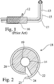
- FIG. 1 is a side view of an insulated heated gas delivery line according to the prior art.
- a tape line heater 13 is run along the pipe 15, following all of the bends 17, turns, and tees of the pipe.
- a layer of insulation material 12 is placed around the pipe by an assembler. This foam insulation is then manually wrapped with tape 16 along the length of the pipe. The entire insulating process is very time consuming and labor intensive.
- the invention provides a removable insulation jacket for fluid carrying conduits, such as heated gas delivery lines.
- Insulation material is affixed or abutted to a semi-rigid, resilient shell to form an insulation jacket.
- the insulation jacket is placed around, and securely encloses, the conduit.
- the jacket is then disengageably sealed, securing the insulation about the conduit.
- the insulation jacket is preferably pleated to conform to any bends and curves that may occur along the length of the conduit. Sections of the insulation jacket are releasably joined to one another by such fasteners as snaps, tape, rings, and junctions.
- the invention provides a removable jacket for thermally insulating fluid carrying conduits, such as heated gas lines. It is also expected that the invention is readily applicable to any other fluid carrying conduit, such as pipelines that are not heated, but that are preferably insulated, and pipelines that are cooled, and that should be insulated to maintain a lower than ambient temperature within the pipeline.
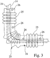
- Fig. 2 is a cross-sectional view of an insulation jacket 18 that is useful for insulating a fluid carrying conduit, such as a heated gas delivery line.
- a heater line 21 may also be affixed to the conduit (see Fig. 3) within the confines of the insulating jacket if the conduit is to be heated.
- the insulation jacket 18 typically has an inner diameter that is sufficient to accommodate and completely surround a fluid carrying conduit 14.
- an inner surface of the insulation jacket may include an insulation layer 20 which may be preformed to conform to the shape of the conduit, and which is composed of an insulating material, such as a fiber based material, or a closed cell foam or polymeric material.
- the insulating material is typically 1/4-inch to three inches in thickness. However, the thickness of the material is readily varied to provide the required level of insulation for a particular application.
- an optional molded inner backing layer 19 may also be included in conjunction with the insulation layer to provide a rigid, yet resilient surface to which the insulating layer may be affixed and which, in connection with an outer shell (discussed below), forms a sandwich-like structure.
- the outer shell 22 may be joined to the insulation material to form an insulation jacket.
- the outer shell is made of a semi-rigid, yet resilient material that removably secures the insulation material about the conduit.
- the outer shell may be formed of such materials as rubberized cloth or polymeric materials, such as polystyrene and polyvinyl chloride.
- the insulation jacket forms a sandwich-like assembly, preferably where the thickness and type of insulation maintain the outer surface of the outer shell at a temperature that is not sufficiently hot that it can burn a worker who may come into contact with the insulation jacket.
- the insulation jacket includes an axial opening the extends along the length of the insulation jacket, and from the outer surface of the outer shell to the inner surface of the backing layer.
- the insulation jacket is thus readily engaged with, and placed around, the conduit along the length of the conduit.
- the insulating jacket includes two edges 23, 24 that extend axially and thereby define the opening. The edges are arranged to either tightly abut one another or such that one edge slightly overlaps the other edge, such that the insulation jacket is disengageably sealed along the length of the opening to maintain thermal continuity about the circumference of, and along the length of, the insulation jacket.
- edges may be secured together to seal the insulation jacket by such means as friction, snaps, interlocking complementary male and female edges, clamps, tie ropes, Velcro-type arrangements, screws, and couplers.
- closure means may also include rings and sleeves adapted to cover a portion of the insulation jacket, thereby holding the opposing ends of consecutive insulating jacket sections together.
- the outer shell of the insulation jacket may be formed of a rigid and resilient polymer material that is molded to exert pressure upon the insulation layer when the insulation jacket is placed around the conduit, such that the insulation jacket may be sealed without the need of a fastener.
- the insulation jacket is preferably installed by cutting it to the length of the conduit, or by joining it to other insulation jackets, as required.
- the insulation jacket thus is an integrated insulator and sealing band, eliminating the need for manually wrapping the insulation layer with tape, and thereby obviating the need for wrapping and unwrapping the conduit as a part of a maintenance or repair regimen.
- the insulation jacket is preferably pleated (as discussed below) to flex when the insulation jacket is fitted over bends, curves, and tees that may be encountered along the length of the conduit, it is quickly and easily fitted over the conduit with minimal labor and material cost.
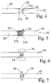
- Fig. 3 is a schematic view of the insulation jacket according to the preferred embodiment of the invention.
- the insulation jacket includes flexible pleats 25 that allow the insulation jacket to conform to bends and curves along the length of the conduit.
- Alternate embodiments of the invention may include separate pleated insulation jackets solely for insulating bends along the path of the conduit, while non-pleated insulation jackets may be provided to insulate straight lengths of the conduit.
- FIG. 3 A schematic view of a snap closure that releasably joins two sections of non-pleated insulation jackets 29, 32 is shown in Fig. 4.
- At least one female snap 28 is provided at an end 27a of a first insulation jacket 29.
- At least one complementary female snap 30 is positioned at an adjoining end 31a of a second insulation jacket 32. The male and female snaps are interengaged to join the insulation jackets together. Individual insulation jackets are readily detached from one another and unfastened to permit access to the underlying conduit and heater (if the conduit is heated).
- the snaps are preferably formed of a non-metallic material such as plastic or nylon, because metal is a thermal conductor and can thereby provide a heat sink that reduces the effectiveness of the insulating jacket, as well as provide a hot spot that might burn a worker when touched.
- Fig. 5 is a schematic view of a taped closure according to an alternate, equally preferred embodiment of the invention.
- the ends 27b, 31b of the first and second insulation jackets 29, 32 are brought together and wrapped with tape 33.
- This embodiment of the invention offers the advantage of providing a seal that is very efficient at holding the heat within the insulation jacket, yet in which the tape only need be removed at the point at which the two sections of insulating jacket are joined to effect maintenance or repair of the underlying conduit/heater.
- the insulation jackets are releasably joined together by means such as a junction closure 34 that provides a pair of opposing, coaxial recesses into which the respective ends of the two insulating jackets may be securely pressed to form a thermally insulative joint, as shown in Fig. 6; and a ring closure 36 that has an inner diameter sufficient to accommodate the outer diameter of the insulating jackets, and that is long enough that at least a portion of an end of each adjoining insulating jacket may be pressed into the ring to form a secure, thermally insulative joint, as shown in Fig. 7, and adapted to receive and hold together the insulation jacket ends.
- a junction closure 34 that provides a pair of opposing, coaxial recesses into which the respective ends of the two insulating jackets may be securely pressed to form a thermally insulative joint, as shown in Fig. 6
- a ring closure 36 that has an inner diameter sufficient to accommodate the outer diameter of the insulating jackets, and that is long enough that at least
- closure means may include, for example sleeves that cover the insulation jacket ends, clamps, tie ropes, Velcro-type arrangements, screws, and couplers.
- end of a first insulation jacket 49 includes a female member 38 that receives and securely holds a male end 40 of a second insulation jacket 48.
- the insulation jacket herein described may be used with other types of conduits, such as refrigerated pipe lines, and electrical conduits.
- the invention is equally applicable to conduits that include an auxiliary heater line, as well as conduits that transport heated fluids.
- the insulation jacket may also be used with heater units, boilers, generators, and refrigeration units.
- the invention is readily used in a semiconductor fabrication clean room, as well as for other industrial uses. Accordingly, the invention should only be limited by the Claims included below.
Landscapes
- Engineering & Computer Science (AREA)
- General Engineering & Computer Science (AREA)
- Mechanical Engineering (AREA)
- Thermal Insulation (AREA)
Applications Claiming Priority (2)
| Application Number | Priority Date | Filing Date | Title |
|---|---|---|---|
| US08/536,714 US5775379A (en) | 1995-09-29 | 1995-09-29 | Insulation jacket for fluid carrying conduits |
| US536714 | 1995-09-29 |
Publications (1)
| Publication Number | Publication Date |
|---|---|
| EP0766035A1 true EP0766035A1 (fr) | 1997-04-02 |
Family
ID=24139629
Family Applications (1)
| Application Number | Title | Priority Date | Filing Date |
|---|---|---|---|
| EP96113915A Withdrawn EP0766035A1 (fr) | 1995-09-29 | 1996-08-30 | Enveloppe calorifuge pour tuyaux de fluide |
Country Status (4)
| Country | Link |
|---|---|
| US (1) | US5775379A (fr) |
| EP (1) | EP0766035A1 (fr) |
| JP (1) | JPH09133288A (fr) |
| KR (1) | KR970016259A (fr) |
Cited By (4)
| Publication number | Priority date | Publication date | Assignee | Title |
|---|---|---|---|---|
| GB2342708A (en) * | 1998-10-13 | 2000-04-19 | Federal Mogul Technology Ltd | Flexible protective sleeve |
| WO2007062508A1 (fr) * | 2005-11-22 | 2007-06-07 | Pratt & Whitney Canada Corp. | Article isolé et procédé d’isolation de l’article |
| EP0896184B2 (fr) † | 1997-07-14 | 2008-01-02 | E. Missel GmbH & Co. | Revêtement isolant pour tuyaux |
| DE202011108011U1 (de) * | 2011-11-17 | 2013-02-18 | Doyma Gmbh & Co | Brandschutzvorrichtung mit integriertem Verschluss |
Families Citing this family (13)
| Publication number | Priority date | Publication date | Assignee | Title |
|---|---|---|---|---|
| US6196272B1 (en) | 1999-02-12 | 2001-03-06 | Mary Maureen Davis | Modular insulated pipe |
| US6315005B1 (en) | 2000-03-06 | 2001-11-13 | Sproule, Iii Charles G. | Water resistant adjustable jackets for insulated pipe bends |
| US6382260B1 (en) | 2000-03-06 | 2002-05-07 | Sproule, Iii Charles G. | Water resistant adjustable jackets for insulated pipe bends |
| JP2002181282A (ja) * | 2000-12-13 | 2002-06-26 | Takayuki Sawada | エルボ保護カバーおよびその製造方法 |
| US7451541B2 (en) * | 2005-02-04 | 2008-11-18 | Pratt & Whitney Canada Corp. | Method of heat shielding an inner tube |
| US20060272727A1 (en) * | 2005-06-06 | 2006-12-07 | Dinon John L | Insulated pipe and method for preparing same |
| US7596914B2 (en) * | 2005-12-15 | 2009-10-06 | Specified Technologies, Inc. | Universal firestopping collar assembly |
| US20100035078A1 (en) * | 2007-01-11 | 2010-02-11 | Staudt Eric K | Embossed thermal shield and methods of construction and installation |
| US20080169038A1 (en) * | 2007-01-11 | 2008-07-17 | Timothy David Sellis | Thermal shield and methods of construction and installation |
| US10208885B2 (en) * | 2008-04-07 | 2019-02-19 | Illinois Tool Works Inc. | Corrosion resistant sheet metal jacketing |
| US8783301B2 (en) | 2010-10-20 | 2014-07-22 | Charles G. Sproule, III | Water resistant adjustable jackets for insulated pipe and pipe bends |
| DE102014209826A1 (de) * | 2014-05-23 | 2015-11-26 | Contitech Ag | Isolierelement bzw. Isoliersystem zur Ummantelung eines Körpers |
| WO2026028257A1 (fr) * | 2024-07-29 | 2026-02-05 | カンケンテクノ株式会社 | Procédé et dispositif pour la fourniture de vapeur d'eau à une conduite de refoulement primaire |
Citations (5)
| Publication number | Priority date | Publication date | Assignee | Title |
|---|---|---|---|---|
| US3095337A (en) * | 1961-07-10 | 1963-06-25 | Gen Foam Plastics Corp | Semicylindrical foam elastomer insulation shell |
| US3126035A (en) * | 1964-03-24 | Espetvedt | ||
| GB2200713A (en) * | 1987-02-09 | 1988-08-10 | Yamato Kogyo Kk | Plastics cover for piping |
| US4823845A (en) * | 1987-09-04 | 1989-04-25 | Manville Corporation | Pipe insulation |
| US5069969A (en) * | 1990-02-28 | 1991-12-03 | Morgan Adhesives Co. | Pressure sensitive adhesive tape with central release liner |
Family Cites Families (10)
| Publication number | Priority date | Publication date | Assignee | Title |
|---|---|---|---|---|
| US2308343A (en) * | 1941-06-06 | 1943-01-12 | Wilkinson Rubber Linatex Ltd | Self-sealing petrol pipe |
| US2364332A (en) * | 1942-04-22 | 1944-12-05 | Wilkinson Rubber Linatex Ltd | Hose pipe |
| US3223125A (en) * | 1961-03-08 | 1965-12-14 | Jack A Melander | Device for forming annular body |
| US3563825A (en) * | 1965-01-26 | 1971-02-16 | Exxon Research Engineering Co | Method for insulating pipelines wherein more insulating material is above the center line of the pipe than below the center line |
| US3557840A (en) * | 1968-05-09 | 1971-01-26 | Atlas Chem Ind | Cellular plastic foam insulation board structures |
| DE1800863A1 (de) * | 1968-10-03 | 1970-05-27 | Kabel Metallwerke Ghh | Mit einem aufschaeumbaren Kunststoff thermisch isoliertes,koaxiales Rohrsystem |
| US3628572A (en) * | 1969-12-29 | 1971-12-21 | Owens Corning Fiberglass Corp | Pipe insulation and method of installing same |
| DK157627C (da) * | 1987-11-06 | 1993-02-08 | Rockwool Int | Element til isolering af isaer krumme roer |
| GB8918218D0 (en) * | 1989-08-09 | 1989-09-20 | Boc Group Plc | Thermal insulation |
| US5400602A (en) * | 1993-07-08 | 1995-03-28 | Cryomedical Sciences, Inc. | Cryogenic transport hose |
-
1995
- 1995-09-29 US US08/536,714 patent/US5775379A/en not_active Expired - Fee Related
-
1996
- 1996-08-30 EP EP96113915A patent/EP0766035A1/fr not_active Withdrawn
- 1996-09-24 KR KR1019960041830A patent/KR970016259A/ko not_active Ceased
- 1996-09-27 JP JP8256790A patent/JPH09133288A/ja not_active Withdrawn
Patent Citations (5)
| Publication number | Priority date | Publication date | Assignee | Title |
|---|---|---|---|---|
| US3126035A (en) * | 1964-03-24 | Espetvedt | ||
| US3095337A (en) * | 1961-07-10 | 1963-06-25 | Gen Foam Plastics Corp | Semicylindrical foam elastomer insulation shell |
| GB2200713A (en) * | 1987-02-09 | 1988-08-10 | Yamato Kogyo Kk | Plastics cover for piping |
| US4823845A (en) * | 1987-09-04 | 1989-04-25 | Manville Corporation | Pipe insulation |
| US5069969A (en) * | 1990-02-28 | 1991-12-03 | Morgan Adhesives Co. | Pressure sensitive adhesive tape with central release liner |
Cited By (6)
| Publication number | Priority date | Publication date | Assignee | Title |
|---|---|---|---|---|
| EP0896184B2 (fr) † | 1997-07-14 | 2008-01-02 | E. Missel GmbH & Co. | Revêtement isolant pour tuyaux |
| GB2342708A (en) * | 1998-10-13 | 2000-04-19 | Federal Mogul Technology Ltd | Flexible protective sleeve |
| GB2342708B (en) * | 1998-10-13 | 2003-02-19 | Federal Mogul Technology Ltd | Flexible protective sleeve |
| WO2007062508A1 (fr) * | 2005-11-22 | 2007-06-07 | Pratt & Whitney Canada Corp. | Article isolé et procédé d’isolation de l’article |
| US7544890B2 (en) | 2005-11-22 | 2009-06-09 | Pratt & Whitney Canada Corp. | Insulated article and method of making same |
| DE202011108011U1 (de) * | 2011-11-17 | 2013-02-18 | Doyma Gmbh & Co | Brandschutzvorrichtung mit integriertem Verschluss |
Also Published As
| Publication number | Publication date |
|---|---|
| JPH09133288A (ja) | 1997-05-20 |
| KR970016259A (ko) | 1997-04-28 |
| US5775379A (en) | 1998-07-07 |
Similar Documents
| Publication | Publication Date | Title |
|---|---|---|
| US5775379A (en) | Insulation jacket for fluid carrying conduits | |
| US4791277A (en) | Heating and insulation arrangement for a network of installed pipes and method | |
| EP0616166B1 (fr) | Conduit de fluides chauffable | |
| US5713394A (en) | Reusable insulation jacket for tubing | |
| US5503193A (en) | Reusable insulation jacket for tubing | |
| US7626146B2 (en) | Modular heater systems | |
| JP4852647B2 (ja) | モジュール式ヒータシステム | |
| US4786088A (en) | Double-containment thermoplastic pipe assembly | |
| US6139068A (en) | Union lock for maintaining connection between two conduits | |
| US4472621A (en) | Separable junction for electrical skin-effect pipeline heating system | |
| US20200314967A1 (en) | Low Profile Heater Apparatus and Method of Manufacture | |
| US7694717B2 (en) | Profile traced insulated cover assembly | |
| US20170030503A1 (en) | Apparatus and method for securing pipe heaters and pipe insulation to pipe systems | |
| EP3548790B1 (fr) | Appareil de serrage et procédé d'utilisation de celui-ci | |
| KR20020020827A (ko) | 히터 장치 | |
| RU2449202C2 (ru) | Система электрического термостатирования трубопроводов или баков | |
| JPH1047581A (ja) | 配管用加熱装置 | |
| GB2283798A (en) | Improvements in or relating to insulation means | |
| JPH04244693A (ja) | 加熱装置を備えた可撓性パイプライン | |
| JPH059590Y2 (fr) | ||
| JP2002246157A (ja) | ヒータ線およびこれを用いた保温移送配管 | |
| DK169262B1 (da) | Varmefordelende monteringssystem til fastspænding af varme-/kølerør på isolerede rør for flydende eller luftformige medier. | |
| RU2069808C1 (ru) | Трубопровод | |
| JPH0235292A (ja) | 流体移送用複合管 | |
| SU1620766A1 (ru) | Трубопровод с электрообогревом |
Legal Events
| Date | Code | Title | Description |
|---|---|---|---|
| PUAI | Public reference made under article 153(3) epc to a published international application that has entered the european phase |
Free format text: ORIGINAL CODE: 0009012 |
|
| AK | Designated contracting states |
Kind code of ref document: A1 Designated state(s): DE GB |
|
| 17P | Request for examination filed |
Effective date: 19970930 |
|
| STAA | Information on the status of an ep patent application or granted ep patent |
Free format text: STATUS: THE APPLICATION HAS BEEN WITHDRAWN |
|
| 17Q | First examination report despatched |
Effective date: 19980922 |
|
| 18W | Application withdrawn |
Withdrawal date: 19981022 |