EP0765733A2 - Verfahren zum Vermindern von Linsen-Fehlern bei der Herstellung von Kontaktlinsen-Halbzeugen - Google Patents
Verfahren zum Vermindern von Linsen-Fehlern bei der Herstellung von Kontaktlinsen-Halbzeugen Download PDFInfo
- Publication number
- EP0765733A2 EP0765733A2 EP96307058A EP96307058A EP0765733A2 EP 0765733 A2 EP0765733 A2 EP 0765733A2 EP 96307058 A EP96307058 A EP 96307058A EP 96307058 A EP96307058 A EP 96307058A EP 0765733 A2 EP0765733 A2 EP 0765733A2
- Authority
- EP
- European Patent Office
- Prior art keywords
- mold
- lens
- contact
- contact lens
- convex
- Prior art date
- Legal status (The legal status is an assumption and is not a legal conclusion. Google has not performed a legal analysis and makes no representation as to the accuracy of the status listed.)
- Granted
Links
Images

Classifications
-
- B—PERFORMING OPERATIONS; TRANSPORTING
- B29—WORKING OF PLASTICS; WORKING OF SUBSTANCES IN A PLASTIC STATE IN GENERAL
- B29D—PRODUCING PARTICULAR ARTICLES FROM PLASTICS OR FROM SUBSTANCES IN A PLASTIC STATE
- B29D11/00—Producing optical elements, e.g. lenses or prisms
- B29D11/00009—Production of simple or compound lenses
- B29D11/00038—Production of contact lenses
- B29D11/00125—Auxiliary operations, e.g. removing oxygen from the mould, conveying moulds from a storage to the production line in an inert atmosphere
-
- B—PERFORMING OPERATIONS; TRANSPORTING
- B29—WORKING OF PLASTICS; WORKING OF SUBSTANCES IN A PLASTIC STATE IN GENERAL
- B29C—SHAPING OR JOINING OF PLASTICS; SHAPING OF MATERIAL IN A PLASTIC STATE, NOT OTHERWISE PROVIDED FOR; AFTER-TREATMENT OF THE SHAPED PRODUCTS, e.g. REPAIRING
- B29C33/00—Moulds or cores; Details thereof or accessories therefor
- B29C33/56—Coatings, e.g. enameled or galvanised; Releasing, lubricating or separating agents
- B29C33/60—Releasing, lubricating or separating agents
-
- B—PERFORMING OPERATIONS; TRANSPORTING
- B29—WORKING OF PLASTICS; WORKING OF SUBSTANCES IN A PLASTIC STATE IN GENERAL
- B29D—PRODUCING PARTICULAR ARTICLES FROM PLASTICS OR FROM SUBSTANCES IN A PLASTIC STATE
- B29D11/00—Producing optical elements, e.g. lenses or prisms
- B29D11/00009—Production of simple or compound lenses
- B29D11/00038—Production of contact lenses
- B29D11/00125—Auxiliary operations, e.g. removing oxygen from the mould, conveying moulds from a storage to the production line in an inert atmosphere
- B29D11/00192—Demoulding, e.g. separating lenses from mould halves
Definitions
- This invention relates to methods for reduction of defects in, and an improvement in yield, in the production of contact lens blanks. More particularly, it provides measures to control and minimize lens blank defects known as lens holes.
- lens blank defects specifically lens holes.
- RMM reactive monomer mix
- a concave or frontcurve mold formed from a hydrophobic polymer such as polystyrene
- a convex or backcurve mold is then brought into proximate engagement with the frontcurve mold to form and shape the lens blank therebetween.
- a mechanically associated assembly formed from the frontcurve mold/RMM/backcurve mold is traversed through a UV curing tunnel under conditions to cure the RMM.
- the cured lens blank products associated with the forming molds are then dissociated by removing the backcurve mold.
- the cured lens/frontcurve assembly is then traversed through leaching and hydration tanks, and a contact lens is thereby produced.
- the continuous process implementing the complete manufacturing process utilizes a lens mold manufacturing zone, comprising first and second injection molding stations for the formation of concave and convex lens molds, respectively, and includes a transport line upon which concave and convex lens parts may be conveyed from zone to zone; an enclosed zone ('nitrogen tunnel') maintained under nitrogen for degassing mold halves or sections; a filling zone for filling concave mold sections with reactive monomer composition, registering concave and convex mold sections in aligned relation, and engaging same in mating molding relation optionally under vacuum conditions, and precuring said reactive monomer composition with ultraviolet light to a gel-like state, and a curing zone in which the cure is completed and the finished lens blank readied for demolding.
- a lens mold manufacturing zone comprising first and second injection molding stations for the formation of concave and convex lens molds, respectively, and includes a transport line upon which concave and convex lens parts may be conveyed from zone to zone; an enclosed zone ('nitrogen
- transport means generally one or more conveyors upon or in relation to which lens molds are assembled, arranged or interleaved in the course of conveyance through the said zones or stations in operational sequence.
- the lens molds may for convenience be situated in or upon mini-pallets (for example, fabricated of cast aluminum, stainless steel or the like) containing a number of lens molds (for example eight) arranged regularly thereon in spatial relation correlated with the treatment stations and the automated material transfer equipment where employed. All of the conveyance belts or tunnels are under nitrogen or inert gaseous blankets.
- the concave or frontcurve mold incorporating an optical molding surface together with a peripheral zone or flange for interactive engagement with the convex or backcurve mold is traversed through a stamping station in which the peripheral flange portion of the mold is treated with a surfactant material without contact with the optical surface of the mold.
- the mold is thereafter filled, sometimes to overflowing with reactive monomer mix whereupon the frontcurve mold is engaged in mating relation with the convex or hackcurve mold, (the optical surface of which is typically untreated); the paired, juxtaposed mold assembly including the RMM molded therebetween, passed to a curing station and thence to a first demolding station at which the mold sections are disengaged.
- the excess material is separated from the remainder of the cured lens blank and retained with the convex or backcurve mold; the optical portion of the lens then is retained by the frontcurve mold, whereupon the excess waste material may be removed from the backcurve mold by any suitable mechanical means, wherefore the frontcurve mold associated with the retained lens blank free of excess peripheral material is passed to leaching and hydration stations, ultimately to be demolded, the contact lenses to be collected, and prepared for shipment.
- injection molds #1 and #2 shown at steps 101 and 102 in the flow diagram of Figure 1, mold respectively front curve and back curve lens mold parts or sections; they may be located in tandem as shown in Figure 2 or to shorten exposure to the atmosphere still further, they may be located in a common plane intersecting a bifurcated transport line, even perpendicularly oriented thereto in the same plane.
- Robotic means 103,104 are provided adjacent the mold registry and engagement station for receiving concave and convex lens molds, respectively and transferring said mold part to a low oxygen environment at a high production cycle rate, as noted at step 105.
- the pallets containing concave and convex lens mold sections are ordered into interleaved relation and degassed when enclosed in feed conveyor such that automated equipment may effect their operative interengagement into molding relation.
- the sequencing conveyor 32 including the interleaving station 40 is enclosed and pressurized over its entire length with an inert gas, conveniently nitrogen.
- an inert gas conveniently nitrogen.
- the amount of nitrogen is not critical, it being suitable to use just enough nitrogen pressure to effectively exclude the atmosphere under the operating conditions experienced.
- the freshly prepared lens mold blanks are degassed as indicated at step 106 in Figure 1.
- the concave lens molds are filled with the reactive monomer composition at step 107 and the concave and convex lens molds are placed into registry and urged into complementary molding relation.
- the filling and assembly zone 50 surrounds a portion of the conveying or transport means 32, which delivers to the zone pallets concave and convex lens mold sections, respectively, and at the terminus of the zone carries pallets of paired and filled molds to the procure zone.
- the filling and assembly zone illustrated in Figure 2 at 50 is defined by a geometrically appropriate, transparent enclosure, generally of rectangular cross-section, formed of any suitable thermoplastic or metal and thermoplastic construction.
- the concave lens mold sections are filled with degassed monomer composition from step 108, and then transported to an assembly module optionally having a vacuum chamber formed intermittently within the nitrogen tunnel in which filled concave lens molds are engaged with convex mold sections in vertical alignment and in mating relation, such that the reactive monomer composition is trapped between the optical surfaces of the respective mold sections and at least partially sealed by the engagement of the parting edge formed peripherally in each of the lens mold sections. If present, the vacuum is released. Then, the mated mold is passed through nitrogen to the precure station, an integral part of the nitrogen tunnel.
- the incipient lens monomer is precured at step 109 in the precure module 60 of the present invention.
- the process of the procure involves clamping the mold halves in registration and then precuring the monomer or monomer mixture to a gel like state.
- the polymerization of the monomer or monomer mixture is completed in curing tunnel 75 as indicated at step 110 with irradiation.
- the monomer/diluent mixture is then cured in a UV oven whereby polymerization is completed in the monomer(s).
- This irradiation with actinic visible or ultraviolet radiation produces a polymer/solvent mixture in the shape of the final desired hydrogel.
- the cure zone also has a source of heat which is effective to raise the temperature of the polymerizable composition to a temperature sufficient to assist the propagation of the polymerization and to counteract the tendency of the polymerizable composition to shrink during the period that it is exposed to the ultraviolet radiation.
- the two halves of the mold are separated during a demolding step leaving the contact lens in the first or front curve mold half 10, from which it is subsequently removed. It should be mentioned that the front and back curve mold halves are used for a single molding and then discarded or disposed of.
- Heating the back curve lens mold creates differential expansion of the heated mold polymer relative to the cooler lens polymer which shifts one surface with respect to the other.
- the resultant shear force breaks the polymerized lens/polymer mold adhesion and assists in the separation of mold portions.
- the greater the temperature gradient between the surfaces of the mold portions the greater the shearing force and the easier the mold portions separate. This effect is greatest when there is maximum thermal gradient.
- heat is lost through conduction from the back mold portion into the lens polymer and the front mold portion, and then collectively into the surrounding environment.
- the heated back mold portion is, therefore, promptly removed so that very little energy is transferred to the polymer lens, avoiding the possibility of thermal decomposition of the lens.
- the heating may be accomplished by techniques known to one skilled in the art such as by steam, laser and the like. The process of laser demolding is described in U.S. Patent No. 5,294,379 to Ross et al.
- the heating step is hot air or steam, after the heating step, the back curve is pried from the front curve and mold in the mold assembly, as indicated at Step 111. If on the other hand, the heating is by laser or infrared, no prying is used and the back curve separates spontaneously from the front curve.
- the demolding assemblies of the mold separation apparatus 90 each physically pry the back curve mold half 30 from the front curve half 10 of each contact lens mold to physically expose each contact lens situated in the lens mold for conveyance to a hydration station for hydration of the lenses.
- the prying process occurs under carefully controlled conditions, so that the back curve half 30 will be separated from the front curve half 10 without destroying the integrity of the lens formed in the lens mold.
- each pallet containing the front curve mold halves with an exposed polymerized contact lens therein is subsequently transported to a hydration station for hydration and demolding from the front curve lens mold, inspection and packaging, as indicated at Step 112.
- Lens defects occur for many reasons, including simple misalignment of manufacturing equipment, but as the latter is readily correctable through engineering adjustment, interest is focussed principally on lens holes and puddles formed in the course of filling and curing steps, employing the reactive monomer mix (RMM).
- RMM reactive monomer mix
- Lens holes include voids i.e. areas which contain no monomer, pits i.e. areas of nonuniform thickness, and other similar regularities such as uneven edges, being a function of the efficiency of spreading of the reactive monomer mix on the surface of the convex backcurve mold when the two mold halves are joined.
- Puddles another lens defect, in random or tree branch shapes generally found along the lens edge, are generated during the curing step, and are associated with the concave or frontcurve mold.
- hydrophilic contact lenses from adherent mold surfaces subsequent to the completion of the contact lens molding process can be facilitated or improved upon, as is set forth in the disclosure of U.S. Patent 5,264,161 to Druskis et al. In that instance, surfactants are introduced in solution into a hydration bath employed in the molding cavities for molding the hydrophilic polymeric structures or contact lenses.
- the surfactant which is dispersed in the hydration bath in concentrations not exceeding 10% by weight aids in facilitating release of the lenses from adherent contiguous mold surfaces being separated, the function of such surfactant being to reduce the surface tension properties of water or liquids, and to thereby reduce the level of adherence between components consisting, on the one hand, of the contact lenses and, on the other hand, the mold surfaces which become adherent during molding.
- Numerous types of surfactants are disclosed in this patent publication, such as polymeric surfactants including polyoxyethylene sorbitan mono-oleates, which are especially suitable for releasing in an undamaged state any hydrophilic polymer articles from adherent mold surfaces which are constituted of plastic materials.
- U.S. Patent 4,159,292 describes the use of silicone wax, stearic acid and mineral oil as additives for plastic mold compositions to improve the contact lens release from the plastic molds.
- the present invention is directed to a method for the modification of the surface energy of hydrophobic contact lens molds to improve wettability and release characteristics thereof to reactive monomer mixtures for hydrophilic hydrogel contact lenses, comprising predominantly acrylate monomers, said method comprising coating the surface of at least one of the mating optical surfaces of said molds with an effective amount of 0.05 to 0.5 by weight of a surfactant, prior to contact of said mold surface with said reactive monomer mixture.
- the present invention further relates to a method for producing hydrogel contact lens blanks comprising forming a lens blank from a UV curable monomer composition adapted for hydrogel contact lenses between mating concave and convex mold surfaces including the steps of depositing the monomer composition in and upon the concave mold surface and engaging the monomer composition with the mating convex mold surface to thereby conform the monomer mixture into the contact lens shape for UV curing, the improvement which comprises applying to the contact surface of the convex mold a surface active agent, to increase the surface area comprising high surface energy domains, in an amount sufficient to reduce lens hole defects realized in contact lens blanks so produced.
- the present invention is still further directed to a method for the modification of the contact surface of a convex mold composed of polystyrene for the production of hydrogel contact lens blanks, to increase the surface areas of high energy domains, thereby to increase the wettability of said surface by a hydrophilic monomer composition for the molding of hydrogel contact lens blanks comprising providing to said contact surface in or prior to the molding cycle a uniform application of a surfactant sufficient to reduce lens hole defects in said contact lens blanks.
- a method for minimizing lens hole defects in the manufacture of hydrogel contact lens comprising modifying the surface energy characteristics of the convex or backcurve mold surface for contact with the reactive monomer mixture for said hydrogel contact lens structures. More specifically, the high energy surface area in the contact face of the convex or backcurve mold is modified to enhance its wettability by the reactive monomer mix.
- the convex mold is pretreated by application of a surface active agent to at least the contact face of the mold by applying, as by spraying, dipping or any other suitable means.
- Such pretreatment may be effected, for example, by spraying on the contact face of the convex mold a surfactant such as Tween 80, Glucam P40 or Glucam DOE 120 appropriately in a solvent vehicle therefor such as water, alcohol or mixtures thereof, to provide a concentration of 0.05 to 5.0% w/w of surfactant.
- the pretreatment may be applied in conjunction with i.e. to precede each mold cycle or may be effected intermittently, to maintain the required surface energy requirements for reduction of lens hole defects.
- the amount of surfactant to be employed will also be gauged by a certain balance between measures taken to ensure desired lens release preferentially from the convex molding surface at this stage; and lens demolding from the concave or frontcurve mold following cure.
- the concave or frontcurve mold may be formed from a composition incorporating a compatible agent such as zinc stearate whereas the surface of the convex or backcurve mold is treated periodically with a surfactant in accordance with this invention as aforesaid.
- lens hole defects can be reduced by as much as several percent in a high speed automated pilot production line thereby effecting substantial economic savings while increasing efficiency of the manufacturing operation.
- Figure 1 is a flow diagram of the continuous process for contact lens production, including molding, treatment and handling of the molds and contact lenses in a low oxygen environment.
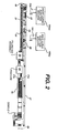
- Figure 2 is a top elevational planar view of the production line system.
- the interfacial tension between the reactive monomer mix, more specifically the advancing meniscus thereof, and the optical surface of the convex or backcurve mold is controlled and minimized by normalizing and extending the surface areas representing high surface energy domains in the convex mold contact surface.
- This is accomplished by the temporal or transient application of a surfactant to the optical surface of the convex mold in amount and characteristics effective to increase the population of the high surface energy areas on the convex mold surface to afford improved wettability by the RMM and effecting a differential in surface energy as between the respective mold halves, to overcome the energy required to separate the two mold halves so to preferentially effect the retention of the optical lens portion on the frontcurve mold.
- the differential referred to favors release from the convex surface, especially because the benefits of reduced lens defects arising from poor wetting of the convex surface with RMM can thereby also be realized.
- surfactant material employed herein is not critical, insofar as it is capable in wetting characteristics relative to RMM and in differential release characteristics relative to the companion mold surface to which it is not applied to achieve the benefits of the invention as outlined herein.
- the surfactant is absorbed into the RMM, or remains to a certain extent on the surface of the lens after hydration, it will be selected with regard to its physiological or pharmaceutical acceptability for human use in eye contact.
- the surface tension modifying characteristics of the surfactant material in the circumstances obtaining will be assessed relative to the desired differential release property; and the surface energy modifying characteristics will be assessed relative to the enhanced wettability for the RMM in relation to the mold surface (in particular, the convex mold surface, as aforesaid) in a manner well known to the artisan.
- the surfactant material is also selected for compatibility with the mold materials and the reactive monomer mix. While, as a consequence, amounts to be applied may differ in response to these characteristics, it has been found that in most cases, a selected application to the mold surface in the range of 0.05 to 5.0 weight % of a solution of the surfactant material is sufficient, usually 0.05 to 2.0 weight %.
- the application of the surfactant where applied to the frontcurve mold remains effective in facilitating release of the contact lens blank from the mold surface after hydration, that is, release from the concave or frontcurve mold, without application of heat or special mechanical manipulation.
- surfactants antistatic agents, ionic surfactants, non-ionic surfactants or lubricant formulations may be employed in the present invention.
- the surfactant constitutes a solution or dispersion of the surface active agents in an essentially inert vehicle to facilitate application to the mold surface by spraying, wiping, vapor deposition, sponging, dipping or the like.
- water, an alkanol or mixtures there may be satisfactorily and economically used to constitute a solution or dispersion of the surface active agent.
- Tween 80 a polyethylene oxide sorbitan monooleate
- Glucamate DOE-120 a polyethylene oxide sorbitan monooleate
- Glucam P-10 a 10 mole propoxylate of methylglucose, available from Amerchol Corporation.
- water soluble or water dispersible materials are preferred for ease of application.
- the mold materials are typically manufactured from hydrophobic materials such as polypropylene or polystyrene, the wettability efficiency for these materials is significant.
- the surfactant is constituted of Tween 80 (registered trademark); i.e., a Polysorbate 80.
- Tween 80 registered trademark
- a Polysorbate 80 This is basically polyethylene oxide sorbitan mono-oleate or the like equivalent, and consists of an oleate ester of sorbitol and its anhydrides copolymerized with approximately 20 moles of ethylene oxide for each mole of sorbitol and sorbitol anhydrides, of generally the formula: [Sum of w, x, y, z is 20; R is (C 17 H 33 )COO]
- Larostat 264 A a soy dimethyl ethyl ammonium ethosulfate sold by PPG
- Armostat 410 an ethoxylated tertiary amine sold by Akzo
- Cystat SN 3-lauramidopropyl trimethylammonium methyl sulfate sold by Cytec
- Atmer 163 N,N-bis (2-hydroxyethyl) alkylamine
- quaternary compounds include the diamidoamines, the imidazoliniums, the dialkyl dimethyl quaternaries, the dialkoxy alkyl quarternaries, and the monoalkyl trimethyl quaternaries. Certain of these materials offer the further advantage of being soluble in RMM and hence are conveniently resorbed into the lens material, leaving the mold surface unaffected upon release and therefore more readily recycled for further use, without cleansing to a base, or neutral condition.
- suitable surfactant materials may be selected from those disclosed in Kirk Othmer, Encyclopedia of Chemical Technology , Vol. 22, p. 379-384 (1983).
- the surface active agent may be applied to the mold surface by spraying or swabbing or dipping, as aforesaid, such that the surface is evenly coated therewith.
- the mold is merely drip-dried with or without the aid of heat and stockpiled for use in the manufacturing process.
- the amount of surfactant so applied is adapted to provide a uniform coating of a 0.05 to 0.5 weight % solution of surfactant on the surface of the mold, as aforesaid.
- the application of the surfactant may alternately be suitably integrated with the manufacturing process such that the mold may be treated immediately prior to their interpolation with the transport mechanism, or just prior to the filling operation, such that the surface thereof is fully wetted, i.e., undried at the point of contact with the reactive monomer mixture.
- the surfactant material such as Tween 80 may be incorporated in the reactive monomer mix at concentrations selected to reduce and control lens hole defects without inducing puddling on the concave mold.
- the molds can be made from any thermoplastic material which is suitable for mass production and can be molded to an optical quality surface and with mechanical properties which will allow the mold to maintain its critical dimensions under the process conditions employed in the process discussed in detail below, and which will allow polymerization with the initiator and radiant energy source contemplated.
- the concave and convex mold members can thus be made from thermoplastic resins.
- suitable materials include polyolefins such as low, medium, and high density polyethylene, polypropylene, including copolymers thereof; poly-4-methylpentene; and polystyrene.
- Other suitable materials are polyacetal resins, polyacrylethers, polyarylether sulfones, nylon 6, nylon 66 and nylon 11.
- Thermoplastic polyesters and various fluorinated materials such as the fluorinated ethylene propylene copolymers and ethylene fluoroethylene copolymers may also be utilized.
- the most preferred material for the molds used in the present process is polystyrene which does not crystallize, has low shrinkage, and can be injection molded at relatively low temperature/to surfaces of optical quality. It will be understood that other thermoplastics, including those mentioned above, may be used provided they have these same properties. Certain copolymers or blends of polyolefins that exhibit these desirable characteristics are also suitable for the present purposes as are polystyrene copolymers and blends having such characteristics, as described more fully in U.S. Patent No. 4,565,348.
- the soft contact lens blanks are formed from a reactive monomer composition which typically incorporates in addition to the reactive monomer a water displaceable diluent in the case of the preparation of a hydrophilic lens, a polymerization catalyst to assist in curing the reactive monomer, a cross-linking agent and often a surfactant to aid in mold release.
- a reactive monomer composition typically incorporates in addition to the reactive monomer a water displaceable diluent in the case of the preparation of a hydrophilic lens, a polymerization catalyst to assist in curing the reactive monomer, a cross-linking agent and often a surfactant to aid in mold release.
- the curable compositions preferably include copolymers based on 2-hydroxyethyl methacrylate ("HEMA”) and one or more comonomers such as 2-hydroxyethyl acrylate, methyl acrylate, methyl methacrylate, vinyl pyrrolidone, N-vinyl acrylamide, hydroxypropyl methacrylate, hydroxyethyl acrylate, hydroxy propyl acrylate, isobutyl methacrylate, styrene, ethoxyethyl methacrylate, methoxy triethyleneglycol methacrylate, glycidyl methacrylate, diacetone acrylamide, vinyl acetate, acrylamide, hydroxytrimethylene acrylate, methoxyethyl methacrylate, acrylic acid, methacrylic acid, glyceryl methacrylate, and dimethylamino ethyl acrylate.
- HEMA 2-hydroxyethyl methacrylate
- compositions are disclosed in U.S. Patent No. 4,495,313 to Larsen, U.S. Patent No. 5,039,459 to Larsen et al. and U.S. Patent No. 4,680,336 to Larsen et al.
- Such compositions comprise anhydrous mixtures of a polymerizable hydrophilic hydroxy ester of acrylic acid, displaceable ester of boric acid and a polyhydroxyl compound having preferably at least 3 hydroxyl groups. Polymerization of such compositions, followed by displacement of the boric acid ester with water, yields a hydrophilic contact lens.
- the mold assembly utilized in the present invention may be employed to make hydrophobic or rigid contact lenses, but the manufacture of hydrophilic lenses is preferred.
- the polymerizable compositions preferably contain a small amount of a cross-linking agent, usually from 0.05 to 2% and most frequently from 0.05 to 1.0%, of a diester or triester.
- a cross-linking agent usually from 0.05 to 2% and most frequently from 0.05 to 1.0%, of a diester or triester.
- representative cross linking agents include: ethylene glycol diacrylate, ethylene glycol dimethacrylate, 1,2-butylene dimethacrylate, 1,3-butylene dimethacrylate, 1,4-butylene dimethacrylate, propylene glycol diacrylate, propylene glycol dimethacrylate, diethylglycol dimethacrylate, glycol dimethacrylate, diethylglycol dimethacrylate, dipropylene glycol dimethacrylate, diethylene glycol diacrylate, dipropylene glycol diacrylate, glycerine trimethacrylate, trimethylol propane triacrylate, trimethylo
- the polymerizable compositions generally also include a catalyst, usually from about 0.05 to 1% of a free radical catalyst.
- a catalyst usually from about 0.05 to 1% of a free radical catalyst.
- Typical examples of such catalysts include lauroyl peroxide, benzoyl peroxide, isopropyl percarbonate, azobisisobutyronitrile and known redox system such as the ammonium persulfate-sodium metabisulfite combination and the like.
- Irradiation by ultraviolet light, electron beam or a radioactive source may also be employed to catalyze the polymerization reaction, optionally with the addition of a polymerization initiator.
- Representative initiators include camphorquinone, ethyl-4-(N,N-dimethyl-amino)benzoate, and 4-(2-hydroxyethoxy)phenyl-2-hydroxyl-2-propyl ketone.
- Polymerization of the polymerizable composition in the mold assembly is preferably carried out by exposing the composition to polymerization initiating conditions.
- the preferred technique is to include in the composition initiators which work upon expose to ultraviolet radiation; and exposing the composition to ultraviolet radiation of an intensity and duration effective to initiate polymerization and to allow it to proceed.
- the mold halves are preferably transparent to ultraviolet radiation.
- the monomer is again exposed to ultraviolet radiation to a cure step in which the polymerization is permitted to proceed to completion. The required duration of the remainder of the reaction can readily be ascertained experimentally for any polymerizable composition.
- the mold assembly comprises at least two pieces, a female concave piece (frontcurve) and a male convex piece (backcurve), forming a cavity therebetween, and when said pieces are mated, at least one piece having a flange thereabout.
- the mold assembly comprises a front mold half and a back mold half in contact therewith, thereby defining and enclosing a cavity therebetween , and a polymerizable composition in said cavity in contact with said mold halves, the front mold of which has a central curved section with a concave section with a concave surface, a convex surface and circular circumferential edge, wherein the portion of said concave surface in contact with said polymerizable composition has the curvature of the frontcurve of a contact lens to be produced in said mold assembly and is sufficiently smooth that the surface of a contact lens formed by polymerization of said polymerizable composition in contact with said surface is optically acceptable, said front mold also having an annular flange integral with and surrounding said circular circumferential edge and extending therefrom in a plane normal to the axis and extending from said flange, while the back mold has a central curved section with a concave surface, convex surface and circular circumferential edge, wherein the portion of said
- the inner concave surface of the front mold half defines the outer surface of the contact lens, while the outer convex surface of the base mold half defines the inner surface of the contact lens which rests upon the edge.
- a convex mold surface which has been pretreated with the surfactant, as aforesaid. is brought into mating engagement with a frontcurve mold and the reactive monomer mix filling the molding cavity therebetween, during which process the optical surface of the convex mold contacts and by reason of its modified surface is efficiently wetted by the RMM such that the advancing meniscus uniformly coats the mold surface without the formation of lens hole defects.
- the convex mold when mechanically separated from the concave mold by reason of its modified surface, efficiently (and consistently throughout the process, involving an interaction of similarly treated molds) releases the lens blank (which remains with the concave mold for curing) without tearing or otherwise damaging the lens blank.
- the frontcurve mold is formed from a composition which comprises an added mold release agent such as zinc stearate, which aids in demolding of the lens blank after hydration.
- an added mold release agent such as zinc stearate
- its surface energy characteristics have been modified and an additional level of surfactant may be required in application to the convex mold surface to balance the release characteristics in such manner as to assure release of the lens blank for retention by the concave or frontcurve mold surface.
- Convex molds were immersed in 2% aqueous solutions of Larostat 264 A (PPG), Armostat 410 (Akzo) and Cystat SN (Cytec), respectively, and then dried under ambient conditions for 48 hours.
- the thus formed coating rendered the surface more wettable by the RMM, a HEMA based composition.
- Polystyrene contact lens molds were swabbed with Glucam P-10, Tween 80 and an aqueous dispersion of Glucam DOE 120, respectively, and the molds were utilized in molding contact lenses employing a reactive monomer mix comprising 96.8% HEMA, 1.97% methacrylic acid, 0.78% ethylene glycol dimethacrylate, and 0.1% of trimethylolpropane trimethacrylate and 0.34% of Darvocur 1173 dispersed (48% RMM) in glycerin boric acid ester as an inert water displaceable diluent.
- the mold halves were readily separated without defects.
- Dimethyl tallow ammonium chloride in solvent/propellant was sprayed onto the optical surface of a backcurve mold.
- a toner powder test showed that the surfactant actives were well dispersed across the mold surface.
Landscapes
- Engineering & Computer Science (AREA)
- Mechanical Engineering (AREA)
- Health & Medical Sciences (AREA)
- Manufacturing & Machinery (AREA)
- Ophthalmology & Optometry (AREA)
- Eyeglasses (AREA)
- Moulds For Moulding Plastics Or The Like (AREA)
- Casting Or Compression Moulding Of Plastics Or The Like (AREA)
- Addition Polymer Or Copolymer, Post-Treatments, Or Chemical Modifications (AREA)
- Solid State Image Pick-Up Elements (AREA)
Applications Claiming Priority (2)
| Application Number | Priority Date | Filing Date | Title |
|---|---|---|---|
| US08/536,944 US5849222A (en) | 1995-09-29 | 1995-09-29 | Method for reducing lens hole defects in production of contact lens blanks |
| US536944 | 1995-09-29 |
Publications (3)
| Publication Number | Publication Date |
|---|---|
| EP0765733A2 true EP0765733A2 (de) | 1997-04-02 |
| EP0765733A3 EP0765733A3 (de) | 1997-10-08 |
| EP0765733B1 EP0765733B1 (de) | 2002-05-08 |
Family
ID=24140562
Family Applications (1)
| Application Number | Title | Priority Date | Filing Date |
|---|---|---|---|
| EP96307058A Expired - Lifetime EP0765733B1 (de) | 1995-09-29 | 1996-09-27 | Verfahren zum Vermindern von Linsen-Fehlern bei der Herstellung von Kontaktlinsen-Halbzeugen |
Country Status (9)
| Country | Link |
|---|---|
| US (1) | US5849222A (de) |
| EP (1) | EP0765733B1 (de) |
| JP (1) | JP4121577B2 (de) |
| AT (1) | ATE217255T1 (de) |
| AU (1) | AU722583B2 (de) |
| CA (1) | CA2186566C (de) |
| DE (1) | DE69621090T2 (de) |
| SG (1) | SG102521A1 (de) |
| TW (1) | TW527276B (de) |
Cited By (9)
| Publication number | Priority date | Publication date | Assignee | Title |
|---|---|---|---|---|
| WO2003095171A1 (en) * | 2002-05-13 | 2003-11-20 | Novartis Ag | Pretreatment of contact lens moulds |
| WO2004022114A1 (en) * | 2002-09-09 | 2004-03-18 | Johnson & Johnson Vision Care, Inc. | Methods of inhibiting the adherence of contact lenses to their packaging |
| WO2006117131A1 (en) * | 2005-04-29 | 2006-11-09 | Novartis Ag | Lens molds with coating |
| WO2007064565A1 (en) * | 2005-11-29 | 2007-06-07 | Bausch & Lomb Incorporated | Method for coating lens material |
| EP1818692A3 (de) * | 2006-02-08 | 2010-05-19 | Johson & Johnson Vision Care Inc. | Ablösungshilfen zur Ablösung ophthalmischer Silikon-Wasserstoff-Linsen |
| US7790824B2 (en) | 2007-07-25 | 2010-09-07 | Alcon, Inc. | High refractive index ophthalmic device materials |
| US8163358B2 (en) | 2009-02-18 | 2012-04-24 | Synergeyes, Inc. | Surface modification of contact lenses |
| WO2015084562A1 (en) * | 2013-12-03 | 2015-06-11 | Johnson & Johnson Vision Care, Inc. | Method for treating a contact lens mold |
| CN116655852A (zh) * | 2023-06-07 | 2023-08-29 | 爱生华(苏州)光学有限公司 | 一种便于脱模的硅水凝胶隐形眼镜的制备方法 |
Families Citing this family (101)
| Publication number | Priority date | Publication date | Assignee | Title |
|---|---|---|---|---|
| WO2000076738A1 (en) | 1999-06-11 | 2000-12-21 | Bausch & Lomb Incorporated | Lens molds with protective coatings for production of contact lenses and other ophthalmic products |
| US7432634B2 (en) | 2000-10-27 | 2008-10-07 | Board Of Regents, University Of Texas System | Remote center compliant flexure device |
| US6873087B1 (en) | 1999-10-29 | 2005-03-29 | Board Of Regents, The University Of Texas System | High precision orientation alignment and gap control stages for imprint lithography processes |
| US6921615B2 (en) * | 2000-07-16 | 2005-07-26 | Board Of Regents, The University Of Texas System | High-resolution overlay alignment methods for imprint lithography |
| EP2270592B1 (de) | 2000-07-17 | 2015-09-02 | Board of Regents, The University of Texas System | Verfahren zur Bildung einer Struktur auf einem Substrat |
| US20050160011A1 (en) * | 2004-01-20 | 2005-07-21 | Molecular Imprints, Inc. | Method for concurrently employing differing materials to form a layer on a substrate |
| US6954275B2 (en) | 2000-08-01 | 2005-10-11 | Boards Of Regents, The University Of Texas System | Methods for high-precision gap and orientation sensing between a transparent template and substrate for imprint lithography |
| AU2001286573A1 (en) | 2000-08-21 | 2002-03-04 | Board Of Regents, The University Of Texas System | Flexure based macro motion translation stage |
| JP2004523906A (ja) | 2000-10-12 | 2004-08-05 | ボード・オブ・リージエンツ,ザ・ユニバーシテイ・オブ・テキサス・システム | 室温かつ低圧マイクロおよびナノ転写リソグラフィのためのテンプレート |
| US6964793B2 (en) | 2002-05-16 | 2005-11-15 | Board Of Regents, The University Of Texas System | Method for fabricating nanoscale patterns in light curable compositions using an electric field |
| US7037639B2 (en) | 2002-05-01 | 2006-05-02 | Molecular Imprints, Inc. | Methods of manufacturing a lithography template |
| US7179079B2 (en) | 2002-07-08 | 2007-02-20 | Molecular Imprints, Inc. | Conforming template for patterning liquids disposed on substrates |
| US6926929B2 (en) * | 2002-07-09 | 2005-08-09 | Molecular Imprints, Inc. | System and method for dispensing liquids |
| US7019819B2 (en) * | 2002-11-13 | 2006-03-28 | Molecular Imprints, Inc. | Chucking system for modulating shapes of substrates |
| US7077992B2 (en) | 2002-07-11 | 2006-07-18 | Molecular Imprints, Inc. | Step and repeat imprint lithography processes |
| US6908861B2 (en) * | 2002-07-11 | 2005-06-21 | Molecular Imprints, Inc. | Method for imprint lithography using an electric field |
| US7442336B2 (en) * | 2003-08-21 | 2008-10-28 | Molecular Imprints, Inc. | Capillary imprinting technique |
| US7070405B2 (en) | 2002-08-01 | 2006-07-04 | Molecular Imprints, Inc. | Alignment systems for imprint lithography |
| US7027156B2 (en) * | 2002-08-01 | 2006-04-11 | Molecular Imprints, Inc. | Scatterometry alignment for imprint lithography |
| US7641840B2 (en) | 2002-11-13 | 2010-01-05 | Molecular Imprints, Inc. | Method for expelling gas positioned between a substrate and a mold |
| US6871558B2 (en) | 2002-12-12 | 2005-03-29 | Molecular Imprints, Inc. | Method for determining characteristics of substrate employing fluid geometries |
| US20040112862A1 (en) * | 2002-12-12 | 2004-06-17 | Molecular Imprints, Inc. | Planarization composition and method of patterning a substrate using the same |
| US7365103B2 (en) * | 2002-12-12 | 2008-04-29 | Board Of Regents, The University Of Texas System | Compositions for dark-field polymerization and method of using the same for imprint lithography processes |
| US7323130B2 (en) * | 2002-12-13 | 2008-01-29 | Molecular Imprints, Inc. | Magnification correction employing out-of-plane distortion of a substrate |
| US7186656B2 (en) | 2004-05-21 | 2007-03-06 | Molecular Imprints, Inc. | Method of forming a recessed structure employing a reverse tone process |
| US7179396B2 (en) | 2003-03-25 | 2007-02-20 | Molecular Imprints, Inc. | Positive tone bi-layer imprint lithography method |
| US7122079B2 (en) | 2004-02-27 | 2006-10-17 | Molecular Imprints, Inc. | Composition for an etching mask comprising a silicon-containing material |
| US7396475B2 (en) | 2003-04-25 | 2008-07-08 | Molecular Imprints, Inc. | Method of forming stepped structures employing imprint lithography |
| US6951173B1 (en) | 2003-05-14 | 2005-10-04 | Molecular Imprints, Inc. | Assembly and method for transferring imprint lithography templates |
| US7307118B2 (en) | 2004-11-24 | 2007-12-11 | Molecular Imprints, Inc. | Composition to reduce adhesion between a conformable region and a mold |
| US7157036B2 (en) | 2003-06-17 | 2007-01-02 | Molecular Imprints, Inc | Method to reduce adhesion between a conformable region and a pattern of a mold |
| US7150622B2 (en) | 2003-07-09 | 2006-12-19 | Molecular Imprints, Inc. | Systems for magnification and distortion correction for imprint lithography processes |
| US7136150B2 (en) | 2003-09-25 | 2006-11-14 | Molecular Imprints, Inc. | Imprint lithography template having opaque alignment marks |
| US8211214B2 (en) | 2003-10-02 | 2012-07-03 | Molecular Imprints, Inc. | Single phase fluid imprint lithography method |
| US7090716B2 (en) * | 2003-10-02 | 2006-08-15 | Molecular Imprints, Inc. | Single phase fluid imprint lithography method |
| US7261830B2 (en) * | 2003-10-16 | 2007-08-28 | Molecular Imprints, Inc. | Applying imprinting material to substrates employing electromagnetic fields |
| US7122482B2 (en) | 2003-10-27 | 2006-10-17 | Molecular Imprints, Inc. | Methods for fabricating patterned features utilizing imprint lithography |
| US20050098534A1 (en) * | 2003-11-12 | 2005-05-12 | Molecular Imprints, Inc. | Formation of conductive templates employing indium tin oxide |
| US20050156353A1 (en) * | 2004-01-15 | 2005-07-21 | Watts Michael P. | Method to improve the flow rate of imprinting material |
| US20050158419A1 (en) * | 2004-01-15 | 2005-07-21 | Watts Michael P. | Thermal processing system for imprint lithography |
| US7019835B2 (en) * | 2004-02-19 | 2006-03-28 | Molecular Imprints, Inc. | Method and system to measure characteristics of a film disposed on a substrate |
| US8076386B2 (en) | 2004-02-23 | 2011-12-13 | Molecular Imprints, Inc. | Materials for imprint lithography |
| US7906180B2 (en) | 2004-02-27 | 2011-03-15 | Molecular Imprints, Inc. | Composition for an etching mask comprising a silicon-containing material |
| US20050189676A1 (en) * | 2004-02-27 | 2005-09-01 | Molecular Imprints, Inc. | Full-wafer or large area imprinting with multiple separated sub-fields for high throughput lithography |
| US7140861B2 (en) | 2004-04-27 | 2006-11-28 | Molecular Imprints, Inc. | Compliant hard template for UV imprinting |
| US20050253307A1 (en) * | 2004-05-11 | 2005-11-17 | Molecualr Imprints, Inc. | Method of patterning a conductive layer on a substrate |
| WO2005119802A2 (en) | 2004-05-28 | 2005-12-15 | Board Of Regents, The University Of Texas System | Adaptive shape substrate support system and method |
| US20050270516A1 (en) * | 2004-06-03 | 2005-12-08 | Molecular Imprints, Inc. | System for magnification and distortion correction during nano-scale manufacturing |
| US20070228593A1 (en) | 2006-04-03 | 2007-10-04 | Molecular Imprints, Inc. | Residual Layer Thickness Measurement and Correction |
| US7785526B2 (en) * | 2004-07-20 | 2010-08-31 | Molecular Imprints, Inc. | Imprint alignment method, system, and template |
| US20060017876A1 (en) * | 2004-07-23 | 2006-01-26 | Molecular Imprints, Inc. | Displays and method for fabricating displays |
| US7309225B2 (en) | 2004-08-13 | 2007-12-18 | Molecular Imprints, Inc. | Moat system for an imprint lithography template |
| US7105452B2 (en) * | 2004-08-13 | 2006-09-12 | Molecular Imprints, Inc. | Method of planarizing a semiconductor substrate with an etching chemistry |
| US7939131B2 (en) | 2004-08-16 | 2011-05-10 | Molecular Imprints, Inc. | Method to provide a layer with uniform etch characteristics |
| US7282550B2 (en) * | 2004-08-16 | 2007-10-16 | Molecular Imprints, Inc. | Composition to provide a layer with uniform etch characteristics |
| US7547504B2 (en) | 2004-09-21 | 2009-06-16 | Molecular Imprints, Inc. | Pattern reversal employing thick residual layers |
| US7252777B2 (en) * | 2004-09-21 | 2007-08-07 | Molecular Imprints, Inc. | Method of forming an in-situ recessed structure |
| US7041604B2 (en) * | 2004-09-21 | 2006-05-09 | Molecular Imprints, Inc. | Method of patterning surfaces while providing greater control of recess anisotropy |
| US7205244B2 (en) | 2004-09-21 | 2007-04-17 | Molecular Imprints | Patterning substrates employing multi-film layers defining etch-differential interfaces |
| US7241395B2 (en) * | 2004-09-21 | 2007-07-10 | Molecular Imprints, Inc. | Reverse tone patterning on surfaces having planarity perturbations |
| US20060062922A1 (en) | 2004-09-23 | 2006-03-23 | Molecular Imprints, Inc. | Polymerization technique to attenuate oxygen inhibition of solidification of liquids and composition therefor |
| US7244386B2 (en) | 2004-09-27 | 2007-07-17 | Molecular Imprints, Inc. | Method of compensating for a volumetric shrinkage of a material disposed upon a substrate to form a substantially planar structure therefrom |
| US7292326B2 (en) | 2004-11-30 | 2007-11-06 | Molecular Imprints, Inc. | Interferometric analysis for the manufacture of nano-scale devices |
| US7630067B2 (en) | 2004-11-30 | 2009-12-08 | Molecular Imprints, Inc. | Interferometric analysis method for the manufacture of nano-scale devices |
| US20070231421A1 (en) | 2006-04-03 | 2007-10-04 | Molecular Imprints, Inc. | Enhanced Multi Channel Alignment |
| US7357876B2 (en) | 2004-12-01 | 2008-04-15 | Molecular Imprints, Inc. | Eliminating printability of sub-resolution defects in imprint lithography |
| US7811505B2 (en) | 2004-12-07 | 2010-10-12 | Molecular Imprints, Inc. | Method for fast filling of templates for imprint lithography using on template dispense |
| US7635263B2 (en) | 2005-01-31 | 2009-12-22 | Molecular Imprints, Inc. | Chucking system comprising an array of fluid chambers |
| US7636999B2 (en) | 2005-01-31 | 2009-12-29 | Molecular Imprints, Inc. | Method of retaining a substrate to a wafer chuck |
| US7256131B2 (en) | 2005-07-19 | 2007-08-14 | Molecular Imprints, Inc. | Method of controlling the critical dimension of structures formed on a substrate |
| US7759407B2 (en) | 2005-07-22 | 2010-07-20 | Molecular Imprints, Inc. | Composition for adhering materials together |
| US8808808B2 (en) | 2005-07-22 | 2014-08-19 | Molecular Imprints, Inc. | Method for imprint lithography utilizing an adhesion primer layer |
| US8557351B2 (en) | 2005-07-22 | 2013-10-15 | Molecular Imprints, Inc. | Method for adhering materials together |
| US7799249B2 (en) * | 2005-08-09 | 2010-09-21 | Coopervision International Holding Company, Lp | Systems and methods for producing silicone hydrogel contact lenses |
| US7320587B2 (en) * | 2005-08-09 | 2008-01-22 | Cooper Vision, Inc. | Contact lens molds and systems and methods for producing same |
| US20070037897A1 (en) * | 2005-08-12 | 2007-02-15 | Guigui Wang | Method for making contact lenses |
| US7665981B2 (en) | 2005-08-25 | 2010-02-23 | Molecular Imprints, Inc. | System to transfer a template transfer body between a motion stage and a docking plate |
| US7670534B2 (en) | 2005-09-21 | 2010-03-02 | Molecular Imprints, Inc. | Method to control an atmosphere between a body and a substrate |
| US8142703B2 (en) * | 2005-10-05 | 2012-03-27 | Molecular Imprints, Inc. | Imprint lithography method |
| US7803308B2 (en) | 2005-12-01 | 2010-09-28 | Molecular Imprints, Inc. | Technique for separating a mold from solidified imprinting material |
| US7906058B2 (en) | 2005-12-01 | 2011-03-15 | Molecular Imprints, Inc. | Bifurcated contact printing technique |
| CN104317161A (zh) | 2005-12-08 | 2015-01-28 | 分子制模股份有限公司 | 用于衬底双面图案形成的方法和系统 |
| US7670530B2 (en) | 2006-01-20 | 2010-03-02 | Molecular Imprints, Inc. | Patterning substrates employing multiple chucks |
| TW200801794A (en) | 2006-04-03 | 2008-01-01 | Molecular Imprints Inc | Method of concurrently patterning a substrate having a plurality of fields and a plurality of alignment marks |
| US7802978B2 (en) | 2006-04-03 | 2010-09-28 | Molecular Imprints, Inc. | Imprinting of partial fields at the edge of the wafer |
| US8850980B2 (en) | 2006-04-03 | 2014-10-07 | Canon Nanotechnologies, Inc. | Tessellated patterns in imprint lithography |
| US8142850B2 (en) | 2006-04-03 | 2012-03-27 | Molecular Imprints, Inc. | Patterning a plurality of fields on a substrate to compensate for differing evaporation times |
| US7547398B2 (en) | 2006-04-18 | 2009-06-16 | Molecular Imprints, Inc. | Self-aligned process for fabricating imprint templates containing variously etched features |
| US8012395B2 (en) | 2006-04-18 | 2011-09-06 | Molecular Imprints, Inc. | Template having alignment marks formed of contrast material |
| US7854867B2 (en) * | 2006-04-21 | 2010-12-21 | Molecular Imprints, Inc. | Method for detecting a particle in a nanoimprint lithography system |
| US8215946B2 (en) | 2006-05-18 | 2012-07-10 | Molecular Imprints, Inc. | Imprint lithography system and method |
| US7811483B2 (en) * | 2006-06-01 | 2010-10-12 | Coopervision International Holding Company, Lp | Delensing of ophthalmic lenses using gas |
| US7968018B2 (en) * | 2007-04-18 | 2011-06-28 | Coopervision International Holding Company, Lp | Use of surfactants in extraction procedures for silicone hydrogel ophthalmic lenses |
| WO2010036639A1 (en) * | 2008-09-24 | 2010-04-01 | Novartis Ag | Method for cast molding contact lenses |
| US8313675B2 (en) * | 2009-08-31 | 2012-11-20 | Coopervision International Holding Company, Lp | Demolding of ophthalmic lenses during the manufacture thereof |
| CN103052364B (zh) * | 2010-07-30 | 2015-12-02 | 诺华股份有限公司 | 具有富水表面的硅水凝胶透镜 |
| SG190218A1 (en) | 2010-11-10 | 2013-06-28 | Novartis Ag | Method for making contact lenses |
| WO2013060787A1 (en) * | 2011-10-28 | 2013-05-02 | Novartis Ag | Method for molding an ophthalmic lens and device for applying a coating to the surface of an ophthalmic lens mold |
| WO2017194095A1 (en) * | 2016-05-10 | 2017-11-16 | Carl Zeiss Vision International Gmbh | Mold and process for preparing spectacle lenses |
| US11256003B2 (en) | 2017-12-13 | 2022-02-22 | Alcon Inc. | Weekly and monthly disposable water gradient contact lenses |
| CN113736005A (zh) * | 2021-09-08 | 2021-12-03 | 安徽新涛光电科技有限公司 | 透镜用亚克力浇铸板及其制备方法 |
Family Cites Families (11)
| Publication number | Priority date | Publication date | Assignee | Title |
|---|---|---|---|---|
| US4159292A (en) * | 1977-05-25 | 1979-06-26 | Neefe Optical Lab. Inc. | Method of controlling the release of a cast plastic lens from a resinous lens mold |
| JPS5695932A (en) * | 1979-12-28 | 1981-08-03 | Tokyo Contact Lens Kenkyusho:Kk | Hydrophilic treatment of surface of methyl methacrylate resin molded article |
| CS239282B1 (en) * | 1983-08-17 | 1986-01-16 | Otto Wichterle | Preparation method of objects made from hydrophilic gelsnamely contact lences by polymer casting |
| US4680336A (en) * | 1984-11-21 | 1987-07-14 | Vistakon, Inc. | Method of forming shaped hydrogel articles |
| JPH01302201A (ja) * | 1988-05-30 | 1989-12-06 | Dainippon Printing Co Ltd | レンズシート成形用樹脂組成物 |
| US4983332A (en) * | 1989-08-21 | 1991-01-08 | Bausch & Lomb Incorporated | Method for manufacturing hydrophilic contact lenses |
| JPH04189112A (ja) * | 1990-11-22 | 1992-07-07 | Seiko Epson Corp | プラスチックレンズの製造方法 |
| US5264161A (en) * | 1991-09-05 | 1993-11-23 | Bausch & Lomb Incorporated | Method of using surfactants as contact lens processing aids |
| US5326505A (en) * | 1992-12-21 | 1994-07-05 | Johnson & Johnson Vision Products, Inc. | Method for treating an ophthalmic lens mold |
| US5542978A (en) * | 1994-06-10 | 1996-08-06 | Johnson & Johnson Vision Products, Inc. | Apparatus for applying a surfactant to mold surfaces |
| US5551663A (en) * | 1994-09-20 | 1996-09-03 | Soane Technologies, Inc. | Plastic molds for ophthalmic devices and methods for forming same |
-
1995
- 1995-09-29 US US08/536,944 patent/US5849222A/en not_active Expired - Lifetime
-
1996
- 1996-09-11 SG SG9610574A patent/SG102521A1/en unknown
- 1996-09-11 AU AU65566/96A patent/AU722583B2/en not_active Expired
- 1996-09-26 CA CA002186566A patent/CA2186566C/en not_active Expired - Lifetime
- 1996-09-27 JP JP27534496A patent/JP4121577B2/ja not_active Expired - Lifetime
- 1996-09-27 EP EP96307058A patent/EP0765733B1/de not_active Expired - Lifetime
- 1996-09-27 AT AT96307058T patent/ATE217255T1/de not_active IP Right Cessation
- 1996-09-27 DE DE69621090T patent/DE69621090T2/de not_active Expired - Lifetime
- 1996-11-11 TW TW085113735A patent/TW527276B/zh not_active IP Right Cessation
Cited By (17)
| Publication number | Priority date | Publication date | Assignee | Title |
|---|---|---|---|---|
| US6867172B2 (en) | 2000-12-07 | 2005-03-15 | Johnson & Johnson Vision Care, Inc. | Methods of inhibiting the adherence of lenses to their packaging |
| WO2003095171A1 (en) * | 2002-05-13 | 2003-11-20 | Novartis Ag | Pretreatment of contact lens moulds |
| CN100581592C (zh) * | 2002-09-09 | 2010-01-20 | 庄臣及庄臣视力保护公司 | 抑制接触透镜与其包装材料粘着的方法 |
| GB2408035B (en) * | 2002-09-09 | 2006-03-15 | Johnson & Johnson Vision Care | Methods of inhibiting the adherence of contact lenses to their packaging |
| GB2408035A (en) * | 2002-09-09 | 2005-05-18 | Johnson & Johnson Vision Care | Methods of inhibiting the adherence of contact lenses to their packaging |
| AU2003268249B2 (en) * | 2002-09-09 | 2009-09-03 | Johnson & Johnson Vision Care, Inc. | Methods of inhibiting the adherence of contact lenses to their packaging |
| WO2004022114A1 (en) * | 2002-09-09 | 2004-03-18 | Johnson & Johnson Vision Care, Inc. | Methods of inhibiting the adherence of contact lenses to their packaging |
| KR101017230B1 (ko) * | 2002-09-09 | 2011-02-25 | 존슨 앤드 존슨 비젼 케어, 인코포레이티드 | 콘택트 렌즈가 이의 팩키지에 부착되는 것을 억제하는 방법 |
| CN101166623B (zh) * | 2005-04-29 | 2010-12-29 | 诺瓦提斯公司 | 具有涂层的透镜模具 |
| WO2006117131A1 (en) * | 2005-04-29 | 2006-11-09 | Novartis Ag | Lens molds with coating |
| WO2007064565A1 (en) * | 2005-11-29 | 2007-06-07 | Bausch & Lomb Incorporated | Method for coating lens material |
| EP1818692A3 (de) * | 2006-02-08 | 2010-05-19 | Johson & Johnson Vision Care Inc. | Ablösungshilfen zur Ablösung ophthalmischer Silikon-Wasserstoff-Linsen |
| AU2007200531B2 (en) * | 2006-02-08 | 2012-01-12 | Johnson & Johnson Vision Care, Inc. | Facilitating release of silicone hydrogel ophthalmic lenses |
| US7790824B2 (en) | 2007-07-25 | 2010-09-07 | Alcon, Inc. | High refractive index ophthalmic device materials |
| US8163358B2 (en) | 2009-02-18 | 2012-04-24 | Synergeyes, Inc. | Surface modification of contact lenses |
| WO2015084562A1 (en) * | 2013-12-03 | 2015-06-11 | Johnson & Johnson Vision Care, Inc. | Method for treating a contact lens mold |
| CN116655852A (zh) * | 2023-06-07 | 2023-08-29 | 爱生华(苏州)光学有限公司 | 一种便于脱模的硅水凝胶隐形眼镜的制备方法 |
Also Published As
| Publication number | Publication date |
|---|---|
| JP4121577B2 (ja) | 2008-07-23 |
| DE69621090T2 (de) | 2002-10-10 |
| US5849222A (en) | 1998-12-15 |
| SG102521A1 (en) | 2004-03-26 |
| ATE217255T1 (de) | 2002-05-15 |
| AU722583B2 (en) | 2000-08-10 |
| CA2186566C (en) | 2007-01-02 |
| EP0765733A3 (de) | 1997-10-08 |
| MX9604513A (es) | 1997-07-31 |
| JPH09183131A (ja) | 1997-07-15 |
| DE69621090D1 (de) | 2002-06-13 |
| CA2186566A1 (en) | 1997-03-30 |
| TW527276B (en) | 2003-04-11 |
| AU6556696A (en) | 1997-04-10 |
| EP0765733B1 (de) | 2002-05-08 |
Similar Documents
| Publication | Publication Date | Title |
|---|---|---|
| EP0765733B1 (de) | Verfahren zum Vermindern von Linsen-Fehlern bei der Herstellung von Kontaktlinsen-Halbzeugen | |
| CA2186565C (en) | Method for transiently wetting lens molds in production of contact lens blanks to reduce lens hole defects | |
| US5690865A (en) | Mold material with additives | |
| EP0765721B1 (de) | Giessform zur Herstellung von Kontaktlinsen | |
| EP0686486B1 (de) | Spritzgiessformteile und Spritzgiessenanlage zur Herstellung von Kontakt-Linsen | |
| EP0785854B2 (de) | Verfahren zur behandlung von kunststoffgiessformen | |
| DE69528686T2 (de) | Sauerstoffarmes Verfahren zur Herstellung von weichen Kontakt-Linsen | |
| BR0109438B1 (pt) | método para fabricar uma lente oftálmica e molde para fabricar lentes oftálmicas. | |
| EP0420403A1 (de) | Verfahren zur Herstellung von hydrophilen Kontaktlinsen | |
| MXPA96004513A (en) | Method for reducing hole faults in the lens in the production of templates for conta lenses | |
| MXPA96004425A (en) | Molding material made with aditi | |
| MXPA96004509A (en) | Method for moisturizing moisturizing molds for lenses in the production of templates for contact lenses, to reduce the defects by holes in the lenses | |
| JP2006150964A (ja) | 二段階眼用レンズ離型法 |
Legal Events
| Date | Code | Title | Description |
|---|---|---|---|
| PUAI | Public reference made under article 153(3) epc to a published international application that has entered the european phase |
Free format text: ORIGINAL CODE: 0009012 |
|
| AK | Designated contracting states |
Kind code of ref document: A2 Designated state(s): AT BE CH DE DK ES FR GB GR IE IT LI NL PT SE |
|
| PUAL | Search report despatched |
Free format text: ORIGINAL CODE: 0009013 |
|
| AK | Designated contracting states |
Kind code of ref document: A3 Designated state(s): AT BE CH DE DK ES FR GB GR IE IT LI NL PT SE |
|
| 17P | Request for examination filed |
Effective date: 19980313 |
|
| 17Q | First examination report despatched |
Effective date: 19990708 |
|
| GRAG | Despatch of communication of intention to grant |
Free format text: ORIGINAL CODE: EPIDOS AGRA |
|
| GRAG | Despatch of communication of intention to grant |
Free format text: ORIGINAL CODE: EPIDOS AGRA |
|
| GRAH | Despatch of communication of intention to grant a patent |
Free format text: ORIGINAL CODE: EPIDOS IGRA |
|
| GRAH | Despatch of communication of intention to grant a patent |
Free format text: ORIGINAL CODE: EPIDOS IGRA |
|
| REG | Reference to a national code |
Ref country code: GB Ref legal event code: IF02 |
|
| GRAA | (expected) grant |
Free format text: ORIGINAL CODE: 0009210 |
|
| AK | Designated contracting states |
Kind code of ref document: B1 Designated state(s): AT BE CH DE DK ES FR GB GR IE IT LI NL PT SE |
|
| PG25 | Lapsed in a contracting state [announced via postgrant information from national office to epo] |
Ref country code: NL Free format text: LAPSE BECAUSE OF FAILURE TO SUBMIT A TRANSLATION OF THE DESCRIPTION OR TO PAY THE FEE WITHIN THE PRESCRIBED TIME-LIMIT Effective date: 20020508 Ref country code: LI Free format text: LAPSE BECAUSE OF FAILURE TO SUBMIT A TRANSLATION OF THE DESCRIPTION OR TO PAY THE FEE WITHIN THE PRESCRIBED TIME-LIMIT Effective date: 20020508 Ref country code: GR Free format text: LAPSE BECAUSE OF FAILURE TO SUBMIT A TRANSLATION OF THE DESCRIPTION OR TO PAY THE FEE WITHIN THE PRESCRIBED TIME-LIMIT Effective date: 20020508 Ref country code: CH Free format text: LAPSE BECAUSE OF FAILURE TO SUBMIT A TRANSLATION OF THE DESCRIPTION OR TO PAY THE FEE WITHIN THE PRESCRIBED TIME-LIMIT Effective date: 20020508 Ref country code: BE Free format text: LAPSE BECAUSE OF FAILURE TO SUBMIT A TRANSLATION OF THE DESCRIPTION OR TO PAY THE FEE WITHIN THE PRESCRIBED TIME-LIMIT Effective date: 20020508 Ref country code: AT Free format text: LAPSE BECAUSE OF FAILURE TO SUBMIT A TRANSLATION OF THE DESCRIPTION OR TO PAY THE FEE WITHIN THE PRESCRIBED TIME-LIMIT Effective date: 20020508 |
|
| REF | Corresponds to: |
Ref document number: 217255 Country of ref document: AT Date of ref document: 20020515 Kind code of ref document: T |
|
| REG | Reference to a national code |
Ref country code: CH Ref legal event code: EP |
|
| REG | Reference to a national code |
Ref country code: IE Ref legal event code: FG4D |
|
| REF | Corresponds to: |
Ref document number: 69621090 Country of ref document: DE Date of ref document: 20020613 |
|
| PG25 | Lapsed in a contracting state [announced via postgrant information from national office to epo] |
Ref country code: SE Free format text: LAPSE BECAUSE OF FAILURE TO SUBMIT A TRANSLATION OF THE DESCRIPTION OR TO PAY THE FEE WITHIN THE PRESCRIBED TIME-LIMIT Effective date: 20020808 Ref country code: PT Free format text: LAPSE BECAUSE OF FAILURE TO SUBMIT A TRANSLATION OF THE DESCRIPTION OR TO PAY THE FEE WITHIN THE PRESCRIBED TIME-LIMIT Effective date: 20020808 Ref country code: DK Free format text: LAPSE BECAUSE OF FAILURE TO SUBMIT A TRANSLATION OF THE DESCRIPTION OR TO PAY THE FEE WITHIN THE PRESCRIBED TIME-LIMIT Effective date: 20020808 |
|
| NLV1 | Nl: lapsed or annulled due to failure to fulfill the requirements of art. 29p and 29m of the patents act | ||
| ET | Fr: translation filed | ||
| REG | Reference to a national code |
Ref country code: CH Ref legal event code: PL |
|
| PG25 | Lapsed in a contracting state [announced via postgrant information from national office to epo] |
Ref country code: ES Free format text: LAPSE BECAUSE OF FAILURE TO SUBMIT A TRANSLATION OF THE DESCRIPTION OR TO PAY THE FEE WITHIN THE PRESCRIBED TIME-LIMIT Effective date: 20021128 |
|
| PLBE | No opposition filed within time limit |
Free format text: ORIGINAL CODE: 0009261 |
|
| STAA | Information on the status of an ep patent application or granted ep patent |
Free format text: STATUS: NO OPPOSITION FILED WITHIN TIME LIMIT |
|
| 26N | No opposition filed |
Effective date: 20030211 |
|
| REG | Reference to a national code |
Ref country code: FR Ref legal event code: PLFP Year of fee payment: 20 |
|
| PGFP | Annual fee paid to national office [announced via postgrant information from national office to epo] |
Ref country code: GB Payment date: 20150923 Year of fee payment: 20 Ref country code: IE Payment date: 20150909 Year of fee payment: 20 Ref country code: DE Payment date: 20150922 Year of fee payment: 20 |
|
| PGFP | Annual fee paid to national office [announced via postgrant information from national office to epo] |
Ref country code: FR Payment date: 20150629 Year of fee payment: 20 |
|
| PGFP | Annual fee paid to national office [announced via postgrant information from national office to epo] |
Ref country code: IT Payment date: 20150925 Year of fee payment: 20 |
|
| REG | Reference to a national code |
Ref country code: DE Ref legal event code: R071 Ref document number: 69621090 Country of ref document: DE |
|
| REG | Reference to a national code |
Ref country code: GB Ref legal event code: PE20 Expiry date: 20160926 |
|
| PG25 | Lapsed in a contracting state [announced via postgrant information from national office to epo] |
Ref country code: GB Free format text: LAPSE BECAUSE OF EXPIRATION OF PROTECTION Effective date: 20160926 |
|
| REG | Reference to a national code |
Ref country code: IE Ref legal event code: MK9A |
|
| PG25 | Lapsed in a contracting state [announced via postgrant information from national office to epo] |
Ref country code: IE Free format text: LAPSE BECAUSE OF EXPIRATION OF PROTECTION Effective date: 20160927 |