EP0765713A2 - Abrasive sheets - Google Patents
Abrasive sheets Download PDFInfo
- Publication number
- EP0765713A2 EP0765713A2 EP96119673A EP96119673A EP0765713A2 EP 0765713 A2 EP0765713 A2 EP 0765713A2 EP 96119673 A EP96119673 A EP 96119673A EP 96119673 A EP96119673 A EP 96119673A EP 0765713 A2 EP0765713 A2 EP 0765713A2
- Authority
- EP
- European Patent Office
- Prior art keywords
- sheet
- tip portion
- body portion
- abrasive sheet
- sanding
- Prior art date
- Legal status (The legal status is an assumption and is not a legal conclusion. Google has not performed a legal analysis and makes no representation as to the accuracy of the status listed.)
- Granted
Links
- 238000005498 polishing Methods 0.000 claims abstract description 13
- 230000000295 complement effect Effects 0.000 claims description 5
- 239000000428 dust Substances 0.000 claims description 5
- XEEYBQQBJWHFJM-UHFFFAOYSA-N Iron Chemical compound [Fe] XEEYBQQBJWHFJM-UHFFFAOYSA-N 0.000 claims description 4
- 229910052742 iron Inorganic materials 0.000 claims description 2
- 238000000034 method Methods 0.000 claims 4
- 244000137852 Petrea volubilis Species 0.000 description 9
- 238000004519 manufacturing process Methods 0.000 description 4
- 239000003082 abrasive agent Substances 0.000 description 1
- 238000000605 extraction Methods 0.000 description 1
- 239000011521 glass Substances 0.000 description 1
- 239000000463 material Substances 0.000 description 1
- 230000004048 modification Effects 0.000 description 1
- 238000012986 modification Methods 0.000 description 1
- 239000011347 resin Substances 0.000 description 1
- 229920005989 resin Polymers 0.000 description 1
- 238000005096 rolling process Methods 0.000 description 1
- 239000004576 sand Substances 0.000 description 1
- 238000010626 work up procedure Methods 0.000 description 1
Images
Classifications
-
- B—PERFORMING OPERATIONS; TRANSPORTING
- B24—GRINDING; POLISHING
- B24D—TOOLS FOR GRINDING, BUFFING OR SHARPENING
- B24D11/00—Constructional features of flexible abrasive materials; Special features in the manufacture of such materials
- B24D11/008—Finishing manufactured abrasive sheets, e.g. cutting, deforming
-
- B—PERFORMING OPERATIONS; TRANSPORTING
- B24—GRINDING; POLISHING
- B24B—MACHINES, DEVICES, OR PROCESSES FOR GRINDING OR POLISHING; DRESSING OR CONDITIONING OF ABRADING SURFACES; FEEDING OF GRINDING, POLISHING, OR LAPPING AGENTS
- B24B23/00—Portable grinding machines, e.g. hand-guided; Accessories therefor
- B24B23/04—Portable grinding machines, e.g. hand-guided; Accessories therefor with oscillating grinding tools; Accessories therefor
-
- Y—GENERAL TAGGING OF NEW TECHNOLOGICAL DEVELOPMENTS; GENERAL TAGGING OF CROSS-SECTIONAL TECHNOLOGIES SPANNING OVER SEVERAL SECTIONS OF THE IPC; TECHNICAL SUBJECTS COVERED BY FORMER USPC CROSS-REFERENCE ART COLLECTIONS [XRACs] AND DIGESTS
- Y10—TECHNICAL SUBJECTS COVERED BY FORMER USPC
- Y10T—TECHNICAL SUBJECTS COVERED BY FORMER US CLASSIFICATION
- Y10T428/00—Stock material or miscellaneous articles
- Y10T428/15—Sheet, web, or layer weakened to permit separation through thickness
-
- Y—GENERAL TAGGING OF NEW TECHNOLOGICAL DEVELOPMENTS; GENERAL TAGGING OF CROSS-SECTIONAL TECHNOLOGIES SPANNING OVER SEVERAL SECTIONS OF THE IPC; TECHNICAL SUBJECTS COVERED BY FORMER USPC CROSS-REFERENCE ART COLLECTIONS [XRACs] AND DIGESTS
- Y10—TECHNICAL SUBJECTS COVERED BY FORMER USPC
- Y10T—TECHNICAL SUBJECTS COVERED BY FORMER US CLASSIFICATION
- Y10T428/00—Stock material or miscellaneous articles
- Y10T428/24—Structurally defined web or sheet [e.g., overall dimension, etc.]
- Y10T428/24008—Structurally defined web or sheet [e.g., overall dimension, etc.] including fastener for attaching to external surface
- Y10T428/24017—Hook or barb
-
- Y—GENERAL TAGGING OF NEW TECHNOLOGICAL DEVELOPMENTS; GENERAL TAGGING OF CROSS-SECTIONAL TECHNOLOGIES SPANNING OVER SEVERAL SECTIONS OF THE IPC; TECHNICAL SUBJECTS COVERED BY FORMER USPC CROSS-REFERENCE ART COLLECTIONS [XRACs] AND DIGESTS
- Y10—TECHNICAL SUBJECTS COVERED BY FORMER USPC
- Y10T—TECHNICAL SUBJECTS COVERED BY FORMER US CLASSIFICATION
- Y10T428/00—Stock material or miscellaneous articles
- Y10T428/24—Structurally defined web or sheet [e.g., overall dimension, etc.]
- Y10T428/24273—Structurally defined web or sheet [e.g., overall dimension, etc.] including aperture
-
- Y—GENERAL TAGGING OF NEW TECHNOLOGICAL DEVELOPMENTS; GENERAL TAGGING OF CROSS-SECTIONAL TECHNOLOGIES SPANNING OVER SEVERAL SECTIONS OF THE IPC; TECHNICAL SUBJECTS COVERED BY FORMER USPC CROSS-REFERENCE ART COLLECTIONS [XRACs] AND DIGESTS
- Y10—TECHNICAL SUBJECTS COVERED BY FORMER USPC
- Y10T—TECHNICAL SUBJECTS COVERED BY FORMER US CLASSIFICATION
- Y10T428/00—Stock material or miscellaneous articles
- Y10T428/24—Structurally defined web or sheet [e.g., overall dimension, etc.]
- Y10T428/24355—Continuous and nonuniform or irregular surface on layer or component [e.g., roofing, etc.]
- Y10T428/24372—Particulate matter
Definitions
- This invention relates to abrasive sheets, such as sandpaper, glass paper or any sheet material used for sanding or polishing.
- Hand-held electric sanders are well known. Many such sanders are designed to carry rectangular sand paper sheets of quarter size, third size or half size, more usually third size sheets. Although such sanders have been very popular, they have not always enabled a user to sand in tight corners, for example. Hence, sanders have been designed to accommodate triangular sheets of sand paper or sheets of sand paper having a shape similar to an iron base. Both of these sheet shapes enable the user of a sander to reach into tight corners of a workpiece to achieve complete sanding of the workpiece.
- a triangular sand paper sheet By providing a sand paper sheet which is triangular, the sheet is effectively provided with three different tips. Hence, since it is usually the tip of a sand paper sheet which wears out first, a triangular sand paper sheet can be made to last up to three times as long as a sheet with only one tip simply by removing the sheet from the base of the sander, rotating the sheet through 120° and replacing the sheet on the sander base. This can, of course, be done twice before the three tips of the sand paper sheet are worn out.
- the iron-shaped sand paper sheet has only tip for use in tight corners of a workpiece.
- the sheet does, however, in general have a greater surface area than a triangular sheet which can be useful when a significant amount of plane sanding is also required.
- the rounded edges of the iron-shaped sheet in the regions approaching the tip of the sheet enable the sander to work up close to a surface perpendicular to the work surface being sanded by the sander, by virtue of the sander "rolling" along the perpendicular surface.
- the present invention aims to improve upon the known prior art iron-shaped sanding sheets by providing a sheet having a plurality of tips.
- an abrasive sheet for a sanding or polishing machine comprising a body portion and a tip portion providing a working point, the tip portion being defined by a weakened region between the body portion and the tip portion, wherein the tip portion can be separated from the body portion, turned through an angle and re-positioned adjacent the body portion to change the working point.
- a complete sanding sheet having an iron-shape for example, can be manufactured from a single sheet, and yet the sheet can still have more than one working point to enable the sheet to last longer, during use.
- the weakened region may comprise a line of perforations.
- a score line may be drawn on the sheet, during manufacture, to define the weakened region.
- Other ways of producing a weakened region may, of course, alternatively be used.
- the tip portion preferably includes four working points.
- an abrasive sheet according to the present invention has a third more working points than a prior art triangular abrasive sheet, for example.
- the tip portion includes four working points, the tip portion is preferably substantially square.
- the tip portion preferably has sides which, when the tip portion is in position adjacent the body portion, complement the sides of the body portion to produce an iron-shaped sheet. More particularly, if the sheet is an iron-shaped sheet, the sides of the tip portion will bulge slightly outwardly to define the curvature of the sheet adjacent the working points. As mentioned above, if a curved surface is provided, it enables the sanding machine to "roll" along a perpendicular wall adjacent a workpiece, thereby sanding right into the corner between the perpendicular wall and the workpiece.
- Apertures may be provided in the sheet through which dust and debris can be removed by a sanding machine, during use.
- dust extraction equipment such as suction devices.
- the attachment means may be hooks or eyes of a VELCRO (Registered Trade Mark)-type fastening system.
- the sanding or polishing machine to which the sheet is to be applied must also be provided with eyes or hooks to receive the hooks or eyes of the abrasive sheet. If a VELCRO-type system is used, the tip portion of the sheet can simply be pulled away from the base of the sanding machine, turned through an angle and placed back on the base of the sanding machine. Hence, a new working point can be provided within seconds.
- an iron-shaped abrasive sheet 1 comprises a body portion 3 and a tip portion 5.
- the sheet 1, during manufacture, is simply cut from a third-size abrasive sheet.
- a line of perforations 7 is also formed during manufacture to define the extent of the tip portion.
- the tip portion 5 is, however, still attached to the body portion 3 at the end of the manufacture of the abrasive sheet 1, so that a complete sheet is purchased by a user of a sanding or polishing machine with a pre-defined working point 11.
- a plurality of apertures 9 are formed in the sheet 1 through which dust and debris can be removed by a suction device of a sanding machine, during use.
- the arrangement of apertures 9 will, of course, need to be designed to satisfy the suction ducts formed in the sanding machine with which the abrasive sheet is to be used.
- the tip portion 5 of the abrasive sheet 1 has edges which are shaped to complement the edges of the body portion 3 to define a complete iron-shape, as shown. Further, if the tip portion 5 is removed from the body portion 3 by tearing of the perforations 7, as shown in Figure 2, the tip portion 5 can be rotated through an angle of, say, 90° and replaced in position adjacent the body portion 3 to produce, once again, an iron-shaped abrasive sheet 1. The working point 11 of the abrasive sheet 1 will, however, have changed.
- the tip portion 5 has four working points 11. Hence, the tip portion 5 can be rotated three times after a working point 11 has been worn out before the complete tip portion becomes useless. This is clearly a significant advantage over the triangular sheets of the prior art.
- the abrasive sheet 1 comprises a support medium 13, such a mesh or web, carrying on one side a layer 15 of abrasive material in a resin and on the other side a layer 17 of loops or eyes of a VELCRO-type fastening system.
- the hooks or eyes of the layer 17 are designed to cooperate with hooks on a base (not shown) of a sanding machine to hold the abrasive sheet 1 in position on the base of the sanding machine.
- a VELCRO-type fastening system By using a VELCRO-type fastening system, the tip portion 5 can easily be removed, rotated and reinstated in position on the base of the sanding machine.
- tip portions 5 having two, three, five, six, seven etc working points 11 could, in theory, alternatively be used.
Landscapes
- Engineering & Computer Science (AREA)
- Mechanical Engineering (AREA)
- Polishing Bodies And Polishing Tools (AREA)
Abstract
Description
- This invention relates to abrasive sheets, such as sandpaper, glass paper or any sheet material used for sanding or polishing.
- Hand-held electric sanders are well known. Many such sanders are designed to carry rectangular sand paper sheets of quarter size, third size or half size, more usually third size sheets. Although such sanders have been very popular, they have not always enabled a user to sand in tight corners, for example. Hence, sanders have been designed to accommodate triangular sheets of sand paper or sheets of sand paper having a shape similar to an iron base. Both of these sheet shapes enable the user of a sander to reach into tight corners of a workpiece to achieve complete sanding of the workpiece.
- By providing a sand paper sheet which is triangular, the sheet is effectively provided with three different tips. Hence, since it is usually the tip of a sand paper sheet which wears out first, a triangular sand paper sheet can be made to last up to three times as long as a sheet with only one tip simply by removing the sheet from the base of the sander, rotating the sheet through 120° and replacing the sheet on the sander base. This can, of course, be done twice before the three tips of the sand paper sheet are worn out.
- In contrast to a triangular sand paper sheet, the iron-shaped sand paper sheet has only tip for use in tight corners of a workpiece. The sheet does, however, in general have a greater surface area than a triangular sheet which can be useful when a significant amount of plane sanding is also required. Further, the rounded edges of the iron-shaped sheet in the regions approaching the tip of the sheet enable the sander to work up close to a surface perpendicular to the work surface being sanded by the sander, by virtue of the sander "rolling" along the perpendicular surface.
- In view of the foregoing, the present invention aims to improve upon the known prior art iron-shaped sanding sheets by providing a sheet having a plurality of tips.
- According to the present invention, there is provided an abrasive sheet for a sanding or polishing machine, comprising a body portion and a tip portion providing a working point, the tip portion being defined by a weakened region between the body portion and the tip portion, wherein the tip portion can be separated from the body portion, turned through an angle and re-positioned adjacent the body portion to change the working point.
- By virtue of the removable tip portion, a complete sanding sheet having an iron-shape, for example, can be manufactured from a single sheet, and yet the sheet can still have more than one working point to enable the sheet to last longer, during use.
- The weakened region may comprise a line of perforations. Alternatively, a score line may be drawn on the sheet, during manufacture, to define the weakened region. Other ways of producing a weakened region may, of course, alternatively be used.
- The tip portion preferably includes four working points. As a result of this, an abrasive sheet according to the present invention has a third more working points than a prior art triangular abrasive sheet, for example.
- If the tip portion includes four working points, the tip portion is preferably substantially square.
- The tip portion preferably has sides which, when the tip portion is in position adjacent the body portion, complement the sides of the body portion to produce an iron-shaped sheet. More particularly, if the sheet is an iron-shaped sheet, the sides of the tip portion will bulge slightly outwardly to define the curvature of the sheet adjacent the working points. As mentioned above, if a curved surface is provided, it enables the sanding machine to "roll" along a perpendicular wall adjacent a workpiece, thereby sanding right into the corner between the perpendicular wall and the workpiece.
- Apertures may be provided in the sheet through which dust and debris can be removed by a sanding machine, during use. With this in mind, many sanding machines now incorporate dust extraction equipment, such as suction devices.
- Although many different ways of attaching an abrasive sheet to a sanding or polishing machine are known, it is preferable that means are provided on one side of the sheet for attaching the sheet to a sanding or polishing machine. The attachment means may be hooks or eyes of a VELCRO (Registered Trade Mark)-type fastening system. In such a case, the sanding or polishing machine to which the sheet is to be applied must also be provided with eyes or hooks to receive the hooks or eyes of the abrasive sheet. If a VELCRO-type system is used, the tip portion of the sheet can simply be pulled away from the base of the sanding machine, turned through an angle and placed back on the base of the sanding machine. Hence, a new working point can be provided within seconds.
- A specific embodiment of the present invention is now described, by way of example only, with reference to the accompanying drawings, in which:
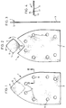
- Figure 1 is a plan view of an abrasive sheet according to the present invention;
- Figure 2 is a plan view of the sheet of Figure 1 with the tip portion of the sheet separated from the body portion of the sheet;
- Figure 3 is a side view of the sheet of Figure 1; and
- Figure 4 is an enlarged sectional side view in the direction IV-IV shown in Figure 1.
- With reference to the drawings, an iron-shaped abrasive sheet 1 comprises a
body portion 3 and atip portion 5. The sheet 1, during manufacture, is simply cut from a third-size abrasive sheet. A line of perforations 7 is also formed during manufacture to define the extent of the tip portion. Thetip portion 5 is, however, still attached to thebody portion 3 at the end of the manufacture of the abrasive sheet 1, so that a complete sheet is purchased by a user of a sanding or polishing machine with a pre-definedworking point 11. - A plurality of
apertures 9 are formed in the sheet 1 through which dust and debris can be removed by a suction device of a sanding machine, during use. The arrangement ofapertures 9 will, of course, need to be designed to satisfy the suction ducts formed in the sanding machine with which the abrasive sheet is to be used. - As can be seen from Figure 1, the
tip portion 5 of the abrasive sheet 1 has edges which are shaped to complement the edges of thebody portion 3 to define a complete iron-shape, as shown. Further, if thetip portion 5 is removed from thebody portion 3 by tearing of the perforations 7, as shown in Figure 2, thetip portion 5 can be rotated through an angle of, say, 90° and replaced in position adjacent thebody portion 3 to produce, once again, an iron-shaped abrasive sheet 1. The workingpoint 11 of the abrasive sheet 1 will, however, have changed. - As shown in the Figures, the
tip portion 5 has fourworking points 11. Hence, thetip portion 5 can be rotated three times after a workingpoint 11 has been worn out before the complete tip portion becomes useless. This is clearly a significant advantage over the triangular sheets of the prior art. - As can be seen from Figure 4 of the drawings, the abrasive sheet 1 comprises a
support medium 13, such a mesh or web, carrying on one side alayer 15 of abrasive material in a resin and on the other side alayer 17 of loops or eyes of a VELCRO-type fastening system. The hooks or eyes of thelayer 17 are designed to cooperate with hooks on a base (not shown) of a sanding machine to hold the abrasive sheet 1 in position on the base of the sanding machine. By using a VELCRO-type fastening system, thetip portion 5 can easily be removed, rotated and reinstated in position on the base of the sanding machine. - Although not specifically disclosed in the drawings,
tip portions 5 having two, three, five, six, seven etcworking points 11 could, in theory, alternatively be used. - It will of course be under stood that the present invention has been described above purely by way of example, and that modifications of detail can be made within the scope of the invention.
Claims (19)
- An abrasive sheet for a sanding or polishing machine characterised in that said sheet comprises a body portion and a tip portion associated therewith, in which said tip portion may be positioned adjacent the body portion to present a working point, whereby said tip portion is rotatable through an angle to be re-positioned adjacent the body portion to change the working point.
- An abrasive sheet as claimed in claim 1 wherein the tip portion includes four working points.
- An abrasive sheet as claimed in claim 2 wherein the tip portion is substantially square.
- An abrasive sheet as claimed in any one of the preceding claims wherein the tip portion has sides which, when the tip portion is in position adjacent the body portion, complement the sides of the body portion to produce an iron-shaped sheet.
- An abrasive sheet as claimed in any one of the preceding claims wherein apertures are provided in the sheet through which dust and debris can be removed by a sanding machine during use.
- An abrasive sheet as claimed in any one of the preceding claims wherein means are provided on one side of the sheet for attaching the sheet to a sanding or polishing machine.
- A method of providing a plurality of working points on an abrasive sheet for a sanding or polishing machine, in which said sheet comprises a body portion, characterised by the steps of providing said body portion with an associated tip portion, said tip portion providing a plurality of working points, positioning said tip portion adjacent the body portion for presenting a working point, rotating said tip portion through a predetermined angle and repositioning it adjacent the body portion to change the working point.
- A method as claimed in claim 7 in which said tip portion is attached to said body portion by a weakened region defining said tip portion, comprising the step of separating said tip portion from said body portion along said weakened region.
- A method as claimed in either claim 7 or claim 8 in which said tip portion comprises four working points, wherein said tip portion is rotated through a predetermined angle of substantially 90°.
- A method as claimed in any one of claims 7 to 9 in which the tip portion is repositioned adjacent the body portion following rotation to complement the sides of the body portion to produce an iron-shaped sheet.
- An abrasive sheet for a sanding or polishing machine characterised by said sheet comprising a plurality of portions, which portions of the plurality may be orientated relative to one another in more than one combination such that the abrasive sheet has an iron shape for each combination and wherein the or each combination provides a different working point.
- An abrasive sheet for a sanding or polishing machine, comprising a body portion and a tip portion providing a working point, the tip portion being defined by a weakened region between the body portion and the tip portion, wherein the tip portion can be separated from the body portion, turned through an angle and re-positioned adjacent the body portion to change the working point.
- An abrasive sheet as claimed in claim 12, wherein the weakened region comprises a line of perforations.
- An abrasive sheet as claimed in claim 12 or claim 13, wherein the tip portion includes four working points.
- An abrasive sheet as claimed in claim 14, wherein the tip portion is substantially square.
- An abrasive sheet as claimed in any preceding claim, wherein the tip portion has sides which, when the tip portion is in position adjacent the body portion, complement the sides of the body portion to produce an iron-shaped sheet.
- An abrasive sheet as claimed in any preceding claim, wherein apertures are provided in the sheet through which dust and debris can be removed by a sanding machine, during use.
- An abrasive sheet as claimed in any preceding claim, wherein means are provided on one side of the sheet for attaching the sheet to a sanding or polishing machine.
- An abrasive sheet as claimed in claim 18, wherein the attachment means are books or eyes of a VELCRO-type fastening system.
Applications Claiming Priority (3)
| Application Number | Priority Date | Filing Date | Title |
|---|---|---|---|
| GB9417272 | 1994-08-25 | ||
| GB9417272A GB9417272D0 (en) | 1994-08-25 | 1994-08-25 | Abrasive sheets |
| EP95305596A EP0699505B1 (en) | 1994-08-25 | 1995-08-10 | Abrasive sheets |
Related Parent Applications (2)
| Application Number | Title | Priority Date | Filing Date |
|---|---|---|---|
| EP95305596.9 Division | 1995-08-10 | ||
| EP95305596A Division EP0699505B1 (en) | 1994-08-25 | 1995-08-10 | Abrasive sheets |
Publications (3)
| Publication Number | Publication Date |
|---|---|
| EP0765713A2 true EP0765713A2 (en) | 1997-04-02 |
| EP0765713A3 EP0765713A3 (en) | 1997-07-30 |
| EP0765713B1 EP0765713B1 (en) | 2001-02-21 |
Family
ID=10760455
Family Applications (2)
| Application Number | Title | Priority Date | Filing Date |
|---|---|---|---|
| EP95305596A Expired - Lifetime EP0699505B1 (en) | 1994-08-25 | 1995-08-10 | Abrasive sheets |
| EP96119673A Expired - Lifetime EP0765713B1 (en) | 1994-08-25 | 1995-08-10 | Abrasive sheets |
Family Applications Before (1)
| Application Number | Title | Priority Date | Filing Date |
|---|---|---|---|
| EP95305596A Expired - Lifetime EP0699505B1 (en) | 1994-08-25 | 1995-08-10 | Abrasive sheets |
Country Status (6)
| Country | Link |
|---|---|
| US (1) | US6045887A (en) |
| EP (2) | EP0699505B1 (en) |
| CA (1) | CA2156199C (en) |
| DE (3) | DE69520143T2 (en) |
| ES (2) | ES2102904T3 (en) |
| GB (1) | GB9417272D0 (en) |
Families Citing this family (15)
| Publication number | Priority date | Publication date | Assignee | Title |
|---|---|---|---|---|
| GB2305875A (en) * | 1995-10-04 | 1997-04-23 | Black & Decker Inc | Detail sanding platen having heat sink adjacent pointed tip |
| GB2305876A (en) * | 1995-10-04 | 1997-04-23 | Black & Decker Inc | Detail sanding platen having detachable portion adjacent pointed tip for replacement when worn |
| NL1015488C2 (en) * | 2000-06-21 | 2001-12-28 | Skil Europ Bv | Orbital sander with interchangeable part of sanding sole. |
| US20020132087A1 (en) * | 2001-03-14 | 2002-09-19 | Wolfgang Coronel | Female engaging surface fastener having a backing and method of making same |
| US20030152737A1 (en) * | 2002-02-08 | 2003-08-14 | Shermer Jason C. | Universal abrasive sheet |
| USD468613S1 (en) | 2002-02-08 | 2003-01-14 | Black & Decker Inc. | Abrasive sheet |
| GB2402641B (en) * | 2003-06-12 | 2005-05-25 | Bosch Gmbh Robert | Sanding plate for a motor-driven hand-held sanding tool |
| USD718601S1 (en) * | 2011-10-31 | 2014-12-02 | 3M Innovative Properties Company | Abrasive article |
| USD718600S1 (en) * | 2011-10-31 | 2014-12-02 | 3M Innovative Properties Company | Abrasive article |
| DE102012004457A1 (en) * | 2012-03-08 | 2013-09-12 | Robert Bosch Gmbh | application tool |
| USD734116S1 (en) * | 2012-06-27 | 2015-07-14 | Kwai Sun Oliver Wong | Replacement head for a hand-held sanding implement |
| DE102012215914A1 (en) * | 2012-09-07 | 2014-03-13 | Robert Bosch Gmbh | Grinding disk for releasably connecting with tool retainer of e.g. vibratory or multi-grinder, has material weakening partially formed in main extending direction of break section, and introduced into base body by laser cutting process |
| CN105150092B (en) * | 2014-06-10 | 2017-06-30 | 南京德朔实业有限公司 | Suitable for the base plate of sander |
| US10611000B1 (en) * | 2019-04-16 | 2020-04-07 | Thomas E. Foster | Flexible sanding block using hook and loop fastener |
| USD915855S1 (en) * | 2019-04-18 | 2021-04-13 | Mirka Ltd | Abrasive sheet |
Family Cites Families (17)
| Publication number | Priority date | Publication date | Assignee | Title |
|---|---|---|---|---|
| US449930A (en) * | 1891-04-07 | dubey | ||
| US1139541A (en) * | 1913-06-17 | 1915-05-18 | Carl Krug | Abrading-disk. |
| US1635350A (en) * | 1923-10-16 | 1927-07-12 | Harry C Simons | Sand, emery, or other abrasive paper, cloth, or the like |
| US2815617A (en) * | 1956-02-17 | 1957-12-10 | Merit Products Inc | Abrasive pad |
| US4274232A (en) * | 1977-09-14 | 1981-06-23 | Minnesota Mining And Manufacturing Company | Friction grip pad |
| US5123216A (en) * | 1985-11-15 | 1992-06-23 | C. & E. Fein Gmbh & Co. | Portable grinder |
| DE3706906A1 (en) * | 1987-03-04 | 1988-09-15 | Fein C & E | GRINDING BODY FOR MOTOR DRIVEN GRINDERS |
| US4930267A (en) * | 1989-05-04 | 1990-06-05 | Demand Products, Inc. | Sanding rasp |
| US5170595A (en) * | 1990-12-19 | 1992-12-15 | Wiand Ronald C | Pull tab for velcro backed marble grinding pad and method for removal |
| US5197998A (en) * | 1992-01-31 | 1993-03-30 | Minnesota Mining And Manufacturing Company | Method of making a folded abrasive article |
| JP2829224B2 (en) * | 1992-08-14 | 1998-11-25 | リョービ モーター プロダクツ コーポレーション | Polishing equipment |
| US5533926A (en) * | 1992-09-04 | 1996-07-09 | Ryobi North America | Sandpaper pad and pad support for a detail sander |
| US5398457A (en) * | 1992-12-11 | 1995-03-21 | Updegrave; Scott A. | Edge and corner sanding attachment |
| DE4303044A1 (en) * | 1993-02-04 | 1994-08-11 | Bosch Gmbh Robert | Hand tool for surface processing |
| GB2275007B (en) * | 1993-02-16 | 1996-01-10 | Unicorn Abrasives Uk Ltd | Abrasive elements |
| USD355105S (en) | 1993-04-20 | 1995-02-07 | Ryobi Motor Products Corp. | Abrasive pad |
| USD389388S (en) | 1996-03-05 | 1998-01-20 | Black & Decker Inc. | Sanding sheet |
-
1994
- 1994-08-25 GB GB9417272A patent/GB9417272D0/en active Pending
-
1995
- 1995-08-10 DE DE69520143T patent/DE69520143T2/en not_active Expired - Lifetime
- 1995-08-10 ES ES95305596T patent/ES2102904T3/en not_active Expired - Lifetime
- 1995-08-10 EP EP95305596A patent/EP0699505B1/en not_active Expired - Lifetime
- 1995-08-10 ES ES96119673T patent/ES2154779T3/en not_active Expired - Lifetime
- 1995-08-10 DE DE29521379U patent/DE29521379U1/en not_active Expired - Lifetime
- 1995-08-10 DE DE69500366T patent/DE69500366T2/en not_active Expired - Lifetime
- 1995-08-10 EP EP96119673A patent/EP0765713B1/en not_active Expired - Lifetime
- 1995-08-16 CA CA002156199A patent/CA2156199C/en not_active Expired - Lifetime
-
1997
- 1997-03-06 US US08/812,199 patent/US6045887A/en not_active Expired - Lifetime
Non-Patent Citations (1)
| Title |
|---|
| None |
Also Published As
| Publication number | Publication date |
|---|---|
| CA2156199A1 (en) | 1996-02-26 |
| DE69520143T2 (en) | 2001-08-23 |
| DE69520143D1 (en) | 2001-03-29 |
| EP0699505B1 (en) | 1997-06-18 |
| DE29521379U1 (en) | 1997-02-27 |
| ES2102904T3 (en) | 1997-08-01 |
| CA2156199C (en) | 2001-11-27 |
| DE69500366T2 (en) | 1997-10-02 |
| US6045887A (en) | 2000-04-04 |
| DE69500366D1 (en) | 1997-07-24 |
| GB9417272D0 (en) | 1994-10-19 |
| EP0765713A3 (en) | 1997-07-30 |
| EP0699505A1 (en) | 1996-03-06 |
| ES2154779T3 (en) | 2001-04-16 |
| EP0765713B1 (en) | 2001-02-21 |
Similar Documents
| Publication | Publication Date | Title |
|---|---|---|
| EP0765713B1 (en) | Abrasive sheets | |
| US8597087B2 (en) | Universal abrasive sheet | |
| US6368199B1 (en) | Backing plates for abrasive disks | |
| EP0882551B1 (en) | Sanding disks | |
| CA2265263C (en) | Universal abrasive disc | |
| US6007415A (en) | Sanding disks | |
| EP0619165A1 (en) | Abrasive article | |
| EP1397230B1 (en) | Abrasive sheet having slots for dust extraction, surface finishing machine and support for said abrasive sheet | |
| US3890746A (en) | Flapper wheel | |
| US6632131B1 (en) | Combination rotary cutting and sanding blade | |
| US6491576B1 (en) | Grinding tool | |
| GB2244945A (en) | Sanding block for use with abrasive bands | |
| JPS6237639Y2 (en) | ||
| JP3020249U (en) | Polishing equipment for blades | |
| JPH069869U (en) | Polishing tool | |
| JPH0432216Y2 (en) | ||
| HK1055921A (en) | Universal abrasive sheet | |
| GB2253630A (en) | Abrasive sheets |
Legal Events
| Date | Code | Title | Description |
|---|---|---|---|
| PUAI | Public reference made under article 153(3) epc to a published international application that has entered the european phase |
Free format text: ORIGINAL CODE: 0009012 |
|
| AC | Divisional application: reference to earlier application |
Ref document number: 699505 Country of ref document: EP |
|
| AK | Designated contracting states |
Kind code of ref document: A2 Designated state(s): CH DE ES FR GB IT LI |
|
| 17P | Request for examination filed |
Effective date: 19970416 |
|
| PUAL | Search report despatched |
Free format text: ORIGINAL CODE: 0009013 |
|
| EL | Fr: translation of claims filed | ||
| 111L | Licence recorded |
Free format text: 970507 0100 BLACK & DECKER (FRANCE) SARL |
|
| AK | Designated contracting states |
Kind code of ref document: A3 Designated state(s): CH DE ES FR GB IT LI |
|
| 111L | Licence recorded |
Free format text: 970507 0100 BLACK & DECKER (FRANCE) S.A.S. |
|
| 17Q | First examination report despatched |
Effective date: 19971222 |
|
| GRAG | Despatch of communication of intention to grant |
Free format text: ORIGINAL CODE: EPIDOS AGRA |
|
| GRAG | Despatch of communication of intention to grant |
Free format text: ORIGINAL CODE: EPIDOS AGRA |
|
| GRAH | Despatch of communication of intention to grant a patent |
Free format text: ORIGINAL CODE: EPIDOS IGRA |
|
| GRAH | Despatch of communication of intention to grant a patent |
Free format text: ORIGINAL CODE: EPIDOS IGRA |
|
| GRAA | (expected) grant |
Free format text: ORIGINAL CODE: 0009210 |
|
| AC | Divisional application: reference to earlier application |
Ref document number: 699505 Country of ref document: EP |
|
| AK | Designated contracting states |
Kind code of ref document: B1 Designated state(s): CH DE ES FR GB IT LI |
|
| REG | Reference to a national code |
Ref country code: CH Ref legal event code: EP |
|
| REF | Corresponds to: |
Ref document number: 69520143 Country of ref document: DE Date of ref document: 20010329 |
|
| ITF | It: translation for a ep patent filed | ||
| REG | Reference to a national code |
Ref country code: ES Ref legal event code: FG2A Ref document number: 2154779 Country of ref document: ES Kind code of ref document: T3 |
|
| REG | Reference to a national code |
Ref country code: CH Ref legal event code: NV Representative=s name: PATENTANWALTSBUREAU R. A. MASPOLI |
|
| ET | Fr: translation filed | ||
| PLBE | No opposition filed within time limit |
Free format text: ORIGINAL CODE: 0009261 |
|
| STAA | Information on the status of an ep patent application or granted ep patent |
Free format text: STATUS: NO OPPOSITION FILED WITHIN TIME LIMIT |
|
| REG | Reference to a national code |
Ref country code: GB Ref legal event code: IF02 |
|
| 26N | No opposition filed | ||
| PGFP | Annual fee paid to national office [announced via postgrant information from national office to epo] |
Ref country code: CH Payment date: 20130828 Year of fee payment: 19 Ref country code: ES Payment date: 20130826 Year of fee payment: 19 Ref country code: DE Payment date: 20130828 Year of fee payment: 19 |
|
| PGFP | Annual fee paid to national office [announced via postgrant information from national office to epo] |
Ref country code: FR Payment date: 20130819 Year of fee payment: 19 Ref country code: GB Payment date: 20130827 Year of fee payment: 19 |
|
| PGFP | Annual fee paid to national office [announced via postgrant information from national office to epo] |
Ref country code: IT Payment date: 20130823 Year of fee payment: 19 |
|
| REG | Reference to a national code |
Ref country code: DE Ref legal event code: R119 Ref document number: 69520143 Country of ref document: DE |
|
| REG | Reference to a national code |
Ref country code: CH Ref legal event code: PL |
|
| GBPC | Gb: european patent ceased through non-payment of renewal fee |
Effective date: 20140810 |
|
| PG25 | Lapsed in a contracting state [announced via postgrant information from national office to epo] |
Ref country code: CH Free format text: LAPSE BECAUSE OF NON-PAYMENT OF DUE FEES Effective date: 20140831 Ref country code: LI Free format text: LAPSE BECAUSE OF NON-PAYMENT OF DUE FEES Effective date: 20140831 Ref country code: IT Free format text: LAPSE BECAUSE OF NON-PAYMENT OF DUE FEES Effective date: 20140810 |
|
| REG | Reference to a national code |
Ref country code: DE Ref legal event code: R119 Ref document number: 69520143 Country of ref document: DE Effective date: 20150303 |
|
| REG | Reference to a national code |
Ref country code: FR Ref legal event code: ST Effective date: 20150430 |
|
| PG25 | Lapsed in a contracting state [announced via postgrant information from national office to epo] |
Ref country code: GB Free format text: LAPSE BECAUSE OF NON-PAYMENT OF DUE FEES Effective date: 20140810 Ref country code: DE Free format text: LAPSE BECAUSE OF NON-PAYMENT OF DUE FEES Effective date: 20150303 |
|
| PG25 | Lapsed in a contracting state [announced via postgrant information from national office to epo] |
Ref country code: FR Free format text: LAPSE BECAUSE OF NON-PAYMENT OF DUE FEES Effective date: 20140901 |
|
| REG | Reference to a national code |
Ref country code: ES Ref legal event code: FD2A Effective date: 20150925 |
|
| PG25 | Lapsed in a contracting state [announced via postgrant information from national office to epo] |
Ref country code: ES Free format text: LAPSE BECAUSE OF NON-PAYMENT OF DUE FEES Effective date: 20140811 |