EP0765620A1 - Vorrichtung zum Hoch- und Herschwenken von Sitzen für eine Teleskoptribüne - Google Patents
Vorrichtung zum Hoch- und Herschwenken von Sitzen für eine Teleskoptribüne Download PDFInfo
- Publication number
- EP0765620A1 EP0765620A1 EP96114954A EP96114954A EP0765620A1 EP 0765620 A1 EP0765620 A1 EP 0765620A1 EP 96114954 A EP96114954 A EP 96114954A EP 96114954 A EP96114954 A EP 96114954A EP 0765620 A1 EP0765620 A1 EP 0765620A1
- Authority
- EP
- European Patent Office
- Prior art keywords
- turning
- coupling pin
- foot members
- drive shaft
- foot
- Prior art date
- Legal status (The legal status is an assumption and is not a legal conclusion. Google has not performed a legal analysis and makes no representation as to the accuracy of the status listed.)
- Granted
Links
Images

Classifications
-
- E—FIXED CONSTRUCTIONS
- E04—BUILDING
- E04H—BUILDINGS OR LIKE STRUCTURES FOR PARTICULAR PURPOSES; SWIMMING OR SPLASH BATHS OR POOLS; MASTS; FENCING; TENTS OR CANOPIES, IN GENERAL
- E04H3/00—Buildings or groups of buildings for public or similar purposes; Institutions, e.g. infirmaries or prisons
- E04H3/10—Buildings or groups of buildings for public or similar purposes; Institutions, e.g. infirmaries or prisons for meetings, entertainments, or sports
- E04H3/12—Tribunes, grandstands or terraces for spectators
- E04H3/123—Telescopic grandstands
-
- A—HUMAN NECESSITIES
- A47—FURNITURE; DOMESTIC ARTICLES OR APPLIANCES; COFFEE MILLS; SPICE MILLS; SUCTION CLEANERS IN GENERAL
- A47C—CHAIRS; SOFAS; BEDS
- A47C1/00—Chairs adapted for special purposes
- A47C1/12—Theatre, auditorium or similar chairs
- A47C1/126—Theatre, auditorium or similar chairs stowable in floor or wall
Definitions
- the present invention relates to the improvement of a turning up and down apparatus for telescopic tiered spectator's seats (hereinafter, abbreviated as a "turning up and down apparatus" installed in halls, gymnasiums and the like.
- Conventional turning up and down apparatuses are arranged such that telescopic spectator's seats, in which a plurality of platforms having seat raising up type chairs installed thereof and arranged in tiers to have a different height are connected to one another to sequentially increase their height, are extended as a whole when the spectator's seats are spread and accommodated in an accommodating space when they are not spread.
- the foot members of the chair are turned up or down by the forward or rearward rotation of a drive shaft and the drive shaft is directly rotated by a motor through a reduction gear (described in Japanese Unexamined Utility Model Publication No. 59-67452).
- the rotational speed of 1800 rpm is reduced to 1/200 of it in the motor and the resultant rotational speed is reduced to 1/2.8 of it by a power unit gear portion, that is, the original rotational speed is reduced to 3.21 rpm of it by the total reduction ratio of 1/560
- the rotational speed of 1500 rpm is reduced to 1/200 of it in the motor and the resultant rotational speed is reduced 1/2.8 of it by the power unit gear portion, that is, the original rotational speed is reduced to 2.68 rpm by the total reduction ratio of 1/560 and there is provided a toggle link mechanism for preventing the rotation of the chairs.
- An object of the present invention is to provide a compact turning up and down apparatus capable of saving energy and space and lowering cost by solving the above problems.
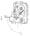
- a turning up and down apparatus for telescopic tiered spectator's seats of the present invention is arranged such that the foot members (3) of each of the chairs are pivotally supported at the lower ends thereof so as to rotate about a spindle (2) as a fulcrum, a drive shaft (14) is disposed to which transmitted is the rotation of an output shaft (10) which is rotated by a forward and rearward rotatable motor (9) disposed on each of the platforms, the rotation of the output shaft (10) being reduced through the combination of gear trains, and the front ends of boomerang-shaped links (23) are coupled with the foot members (3) by a foot member coupling pin (24) and the rear ends thereof are supported by a rear end coupling pin (21), wherein when the foot members (3) are in a turned up state, since the links (23) are pressed against the drive shaft (14) and the center (P) of the rear end coupling pin (21) is located at the position which is determined by getting over the straight line a small angle ( ⁇ ) clockwise which is extended from the center (Q) of the foot
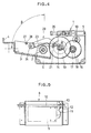
- FIG. 1 to FIG. 4 do not show chairs and components located in the vicinity thereof, a plurality of platforms of telescopic tiered spectator's seats, which have seat raising up type chairs installed thereon and are arranged in tiers to have a different height, are operably connected to one another to sequentially increase their height and seat raising up type chairs are installed on the platform in each tier, each of the platforms being arranged to extend forward and contract rearward.
- a plurality of the chairs each having a seat are disposed adjacent to one another in a lateral line with intervals therebetween in the right to left direction on the upper surface of each platform on the side near to the rear end thereof and a turning up and down apparatus 1 is disposed in correspondence to each chair.
- the turning up and down apparatus 1 and a drive unit 8 will be described below.
- the drive unit 8 is mounted in a fixed frame 13 as a unit as a whole in such an arrangement that a geared motor 9 with a brake rotatable forward and rearward is disposed in the fixed frame 13 and an output shaft 10 coupled with the shaft of the motor 9 through spur gears 11, 12 is pivotally supported by bearings at the both ends thereof.
- the rotation of the geared motor 9 is transmitted to the output shaft 10 through the spur gears 11 and 12 so that it is rotated forward and rearward.
- the turning up and down apparatus 1 includes foot members 3 fixed to and standing from a spindle 2, a passing-through bar 4 fixed to the upper ends of the foot members 3 and disposed laterally and a turning up and down chair fixed to and standing from the passing-through bar 4 at the respective lower ends thereof in a lengthwise direction from the right to the left with intervals therebetween.
- the chair is composed of support legs, a seat, arms and a back (the chair is not shown in the drawings).
- the foot members 3 are pivotally mounted to rotate a rotational angle ⁇ (usually 90°) using the spindle 2 of the turning up and down unit 1 as a fulcrum, respectively, so that the chair on the foot members 3 can be turned up and down as a whole. That is, a lateral decorated box 6 which is long in the right to left direction is disposed on the upper surface of the platform at the rear portion thereof and the turning up and down unit 1 having the spindle 2 is fixedly disposed with intervals on the right and left sides thereof so as to be accommodated in the decorated box 6.
- a rotational angle ⁇ usually 90°
- the output shaft 10 projects from the drive unit 8 to both the right and left directions or to any one of the right and left directions and introduced into the turning up and down unit 1.
- the turning up and down unit 1 has respective gear trains arranged such that the output shaft 10 rotatably passes through the box-shaped fixed frame 5 of the decorated box 6 on the upper rear portion thereof in the right to left direction, the rotational speed of the output shaft 10 is reduced in a first stage through the small gear 15 fixedly mounted to the output shaft 10 and a large gear 16 and further reduced in a second stage through the small gear 18 fixedly mounted to the gear shaft 17 of the large gear 16 and the large gear 19 fixedly mounted to a drive shaft 14 located approximately at the center of the fixed frame 5.
- the spindle 2 is laterally disposed in the right to left direction at a front lower portion of the drive shaft 14 and rotatably supports the foot members 3 at the lower ends thereof at positions spaced apart from each other and a turning up and down mechanism 20 is disposed in the fixed frame 5 which rotates the foot members 3 the aforesaid rotational angle ⁇ (usually 90°) about the spindle 2 to thereby turn up or down the foot members 3 as the drive shaft 14 rotates a rotational angle ⁇ forward and rearward.
- a turning up and down mechanism 20 is disposed in the fixed frame 5 which rotates the foot members 3 the aforesaid rotational angle ⁇ (usually 90°) about the spindle 2 to thereby turn up or down the foot members 3 as the drive shaft 14 rotates a rotational angle ⁇ forward and rearward.
- the turning up and down mechanism 20 is composed of a pair of right and left boomerang-shaped links 23, 23 supported by a foot member coupling pin 24 at the front end thereof which passes through the foot members 3 at a position thereof a little higher than the intermediate position in the vertical direction of the foot members 3 and a rear end coupling pin 21 at the rear end thereof which passes through the large gear 19 integrally mounted to the drive shaft 14 at a position near to the end of the gear 19 to thereby couple the rear end coupling pin 21 of the large gear 19 which is rotated by the forward and rearward rotation of the drive shaft 14 with the foot member coupling pin 24.
- the large gear 19 is rotated forward and rearward the rotational angle ⁇ by the forward and rearward rotation of the drive shaft 14 integrally therewith and the links 23, 23 are pushed out forward or pulled in rearward by the rotation of the large gear 19, so that the foot members 3 are rotated the rotational angle ⁇ (usually 90°) about the spindle 2 as a fulcrum and can be turned up or down.
- the apparatus can be made compact. Further, a degree of freedom in design can be increased by changing the position where the rear end coupling pin 21 is mounted.
- the fine adjustment of the angle ⁇ between the line QC and the line CP is made possible by such an arrangement that adjusting bolts 26 finely adjustable forward and rearward are disposed on the upper portion plate of the fixed frame 5 and stoppers 27 fixed to the grooves 28 defined to the turning up foot members 3 by welding or the like serve to determine stop positions and the adjusting bolts 26 are finely adjusted forward and rearward.
- the rotational speed of the output shaft 10 transmitted from the motor 9 being rotated is reduced by the combination of the gear trains composed of the small gears and the large gears as described above, the rotational speed is transmitted to the drive shaft 14 by being reduced to a final rotational speed preferably in the two stages of the small and large gear trains such as the gear trains composed of, for example, the gears 15, 16 and the gears 18, 19.
- the volume of the motor 9 can be reduced, the diameter of the output shaft 10 can be reduced due to the power transmission at high rotation and low torque, a phase difference and a power loss caused by twist can be removed and the turning up and down apparatus can save energy and space and lower cost.
- a less amount of power loss is caused because the rotational speed is reduced by the gear trains in place of a worm nd a worm gear, thus energy can be saved.
- the rotational speed of a geared motor used as the motor 9 is transmitted to the output shaft 10 by being reduced to 1/30 of it, the numbers of the teeth of the gears 15, 16, 18, 19 of the gear trains are set to 16, 74, 14 and 62 to thereby reduce the rotational speed of the drive shaft 14 to 1/20.482 of that of the output shaft 10 and the speed reduction ratio of the rotational speed to be transmitted from the motor 9 to the drive shaft 14 is set to 1/614.46.
- the rotational angle ⁇ of the drive shaft 14 when it is rotated forward and rearward (which is the same as the rotational angle of the large gear 9 when it is rotated forward and rearward) is set to 200°.
- the present invention when the foot members are in a turned up state, since the links are pressed against the drive shaft and the center of the rear end coupling pin is located at the position which is determined by getting over the straight line a small angle clockwise which is extended from the center of the foot member coupling pin through the center of the drive shaft, even if an external force for turning down the foot members forward is applied, the turning down thereof forward can be perfectly prevented. Further, the rear end coupling pin is mounted to the large gear by being passed through, the apparatus can be made compact.
Landscapes
- Engineering & Computer Science (AREA)
- Architecture (AREA)
- Civil Engineering (AREA)
- Structural Engineering (AREA)
- Health & Medical Sciences (AREA)
- Dentistry (AREA)
- General Health & Medical Sciences (AREA)
- Chairs For Special Purposes, Such As Reclining Chairs (AREA)
- Gear Transmission (AREA)
Applications Claiming Priority (3)
| Application Number | Priority Date | Filing Date | Title |
|---|---|---|---|
| JP7289113A JP2948516B2 (ja) | 1995-09-29 | 1995-09-29 | 伸縮式階段状観覧席の起立転倒装置 |
| JP28911395 | 1995-09-29 | ||
| JP289113/95 | 1995-09-29 |
Publications (2)
| Publication Number | Publication Date |
|---|---|
| EP0765620A1 true EP0765620A1 (de) | 1997-04-02 |
| EP0765620B1 EP0765620B1 (de) | 2001-07-11 |
Family
ID=17738959
Family Applications (1)
| Application Number | Title | Priority Date | Filing Date |
|---|---|---|---|
| EP96114954A Expired - Lifetime EP0765620B1 (de) | 1995-09-29 | 1996-09-18 | Vorrichtung zum Hoch- und Herschwenken von Sitzen für eine Teleskoptribüne |
Country Status (4)
| Country | Link |
|---|---|
| US (1) | US5819475A (de) |
| EP (1) | EP0765620B1 (de) |
| JP (1) | JP2948516B2 (de) |
| DE (1) | DE69613784T2 (de) |
Cited By (1)
| Publication number | Priority date | Publication date | Assignee | Title |
|---|---|---|---|---|
| WO2008132690A3 (en) * | 2007-04-26 | 2009-03-26 | Poltrona Frau Spa | A modular unit for a flooring structure for theatre auditoriums and the like |
Families Citing this family (12)
| Publication number | Priority date | Publication date | Assignee | Title |
|---|---|---|---|---|
| EP0969166B1 (de) * | 1998-01-14 | 2007-02-28 | KabushikiKaisha Kotobuki | Sitzaufbau und falteinrichtung für einen transportierbaren zuschauerplatz |
| US6539672B1 (en) | 1999-09-25 | 2003-04-01 | Colin C. Frost | Telescopic seating system tier catch and method |
| US6293053B1 (en) * | 1999-12-21 | 2001-09-25 | Specialty Supply & Installation | Non friction direct drive power system |
| US7303235B1 (en) * | 2004-01-20 | 2007-12-04 | Preferred Engineering | Chair for venues with tiered seating |
| KR100751386B1 (ko) * | 2004-08-31 | 2007-08-22 | 주식회사 유니테크 시스템 | 보조관람석단을 갖는 수납식 관람석 |
| CN101796254B (zh) * | 2007-06-08 | 2012-12-05 | 斯蒂尔戴科工业有限公司 | 讲台及用于讲台的支撑结构 |
| CA2740563C (en) * | 2008-11-21 | 2017-09-12 | Gestion Laforest Inc. | Removable seats system |
| EP2224076B1 (de) * | 2009-02-27 | 2013-06-05 | M-T Patents GmbH | Tribüne |
| US8438786B2 (en) * | 2009-07-23 | 2013-05-14 | Irwin Seating Company | Flexible venue system |
| US9115505B2 (en) * | 2011-07-22 | 2015-08-25 | Irwin Seating Company | Nosemount seating system |
| US9752338B2 (en) | 2014-08-10 | 2017-09-05 | Richard D. Strayer, JR. | Vertical support apparatus for a telescoping seating system |
| US11659929B2 (en) * | 2019-09-06 | 2023-05-30 | Hussey Seating Company | Double action nose mount quattro stanchion |
Citations (2)
| Publication number | Priority date | Publication date | Assignee | Title |
|---|---|---|---|---|
| JPS5967452U (ja) * | 1982-10-27 | 1984-05-07 | 株式会社コトブキ | 伸縮式階段状観覧席 |
| EP0452918A1 (de) * | 1990-04-18 | 1991-10-23 | Kabushiki Kaisha Kotobuki | Vorrichtung zum automatischen Aufrichten von Sitzen für eine Teleskoptribüne |
Family Cites Families (9)
| Publication number | Priority date | Publication date | Assignee | Title |
|---|---|---|---|---|
| US4063392A (en) * | 1977-02-11 | 1977-12-20 | American Seating Company | Telescoping seating system with automatically folding chairs |
| US4155202A (en) * | 1978-04-03 | 1979-05-22 | American Seating Company | Telescoping seating system with automatically folding chairs |
| US4446659A (en) * | 1982-12-20 | 1984-05-08 | American Seating Company | Automatic seating for telescoping row systems |
| JPS60102468A (ja) * | 1983-11-07 | 1985-06-06 | 株式会社コトブキ | 伸縮式階段状観覧席の椅子起立転倒装置 |
| JPS62201109A (ja) * | 1986-02-28 | 1987-09-04 | 株式会社コトブキ | 伸縮式階段状観覧席の椅子自動起立転倒装置 |
| US5271190A (en) * | 1990-11-30 | 1993-12-21 | Kabushiki Kaisha Kotobuki | Apparatus for opening and closing covering means for furniture raising/lowering type floor equipment |
| JP2579193Y2 (ja) * | 1991-10-31 | 1998-08-20 | 株式会社コトブキ | 移動観覧席用椅子 |
| JP2743712B2 (ja) * | 1992-05-18 | 1998-04-22 | コクヨ株式会社 | 伸縮移動観覧席における椅子の起伏機構 |
| FR2701642B1 (fr) * | 1993-02-17 | 1995-05-19 | Doublet Ets | Perfectionnements aux tribunes à gradins, à éléments télescopiques. |
-
1995
- 1995-09-29 JP JP7289113A patent/JP2948516B2/ja not_active Expired - Fee Related
-
1996
- 1996-09-18 EP EP96114954A patent/EP0765620B1/de not_active Expired - Lifetime
- 1996-09-18 DE DE69613784T patent/DE69613784T2/de not_active Expired - Lifetime
- 1996-09-27 US US08/723,221 patent/US5819475A/en not_active Expired - Lifetime
Patent Citations (2)
| Publication number | Priority date | Publication date | Assignee | Title |
|---|---|---|---|---|
| JPS5967452U (ja) * | 1982-10-27 | 1984-05-07 | 株式会社コトブキ | 伸縮式階段状観覧席 |
| EP0452918A1 (de) * | 1990-04-18 | 1991-10-23 | Kabushiki Kaisha Kotobuki | Vorrichtung zum automatischen Aufrichten von Sitzen für eine Teleskoptribüne |
Cited By (1)
| Publication number | Priority date | Publication date | Assignee | Title |
|---|---|---|---|---|
| WO2008132690A3 (en) * | 2007-04-26 | 2009-03-26 | Poltrona Frau Spa | A modular unit for a flooring structure for theatre auditoriums and the like |
Also Published As
| Publication number | Publication date |
|---|---|
| EP0765620B1 (de) | 2001-07-11 |
| JPH0996116A (ja) | 1997-04-08 |
| US5819475A (en) | 1998-10-13 |
| DE69613784T2 (de) | 2002-03-07 |
| DE69613784D1 (de) | 2001-08-16 |
| JP2948516B2 (ja) | 1999-09-13 |
Similar Documents
| Publication | Publication Date | Title |
|---|---|---|
| US5819475A (en) | Turning up and down apparatus for telescopic tiered spectator's seats | |
| KR200193359Y1 (ko) | 휠체어용 전동장치 | |
| AU736774B2 (en) | Transport device | |
| US5951444A (en) | Cable and pulley linkage for exercise machine | |
| US6763536B2 (en) | Motor adjustable support device for the upholstery of a piece of furniture that is used for sitting and/or laying upon | |
| US6029763A (en) | Worm gear assembly for a medical mobility apparatus permitting manual reverse mobility | |
| US6385801B1 (en) | Rocking bed | |
| US6152478A (en) | Wheelchair with a pivoting back, seat and leg supports | |
| US11540505B2 (en) | Motorized stand | |
| US5241914A (en) | Work table or office desk | |
| JPS60157935A (ja) | シ−ト調整装置 | |
| US4738445A (en) | Ergometer | |
| US6527340B1 (en) | Apparatus and method for tilting the seat of a wheelchair with a low profile linkage | |
| WO1999026517A1 (en) | An armchair with power-driven footrest, back and base seat | |
| US20110265784A1 (en) | Solar tracker | |
| JPS6316777Y2 (de) | ||
| JP2743712B2 (ja) | 伸縮移動観覧席における椅子の起伏機構 | |
| JP2554260Y2 (ja) | 折りたたみ椅子連動起立転倒装置 | |
| JP3080427B2 (ja) | パワーシート装置 | |
| KR0131939B1 (ko) | 상하 및 좌우 위치조정이 동시에 가능한 시트용 링크 | |
| EP0737491A1 (de) | Mehrzweckübungsgerät | |
| KR100255978B1 (ko) | 크레인의 유압시스템용 다중조종장치 | |
| CN212047720U (zh) | 一种太极休闲车 | |
| KR970001464Y1 (ko) | 의자등받이 구동장치 | |
| WO1996009196A1 (en) | Trailer support device |
Legal Events
| Date | Code | Title | Description |
|---|---|---|---|
| PUAI | Public reference made under article 153(3) epc to a published international application that has entered the european phase |
Free format text: ORIGINAL CODE: 0009012 |
|
| 17P | Request for examination filed |
Effective date: 19960918 |
|
| AK | Designated contracting states |
Kind code of ref document: A1 Designated state(s): BE DE ES FR GB IE IT LU NL |
|
| 17Q | First examination report despatched |
Effective date: 20000313 |
|
| GRAG | Despatch of communication of intention to grant |
Free format text: ORIGINAL CODE: EPIDOS AGRA |
|
| GRAG | Despatch of communication of intention to grant |
Free format text: ORIGINAL CODE: EPIDOS AGRA |
|
| GRAH | Despatch of communication of intention to grant a patent |
Free format text: ORIGINAL CODE: EPIDOS IGRA |
|
| GRAH | Despatch of communication of intention to grant a patent |
Free format text: ORIGINAL CODE: EPIDOS IGRA |
|
| GRAA | (expected) grant |
Free format text: ORIGINAL CODE: 0009210 |
|
| AK | Designated contracting states |
Kind code of ref document: B1 Designated state(s): BE DE ES FR GB IE IT LU NL |
|
| PG25 | Lapsed in a contracting state [announced via postgrant information from national office to epo] |
Ref country code: NL Free format text: LAPSE BECAUSE OF FAILURE TO SUBMIT A TRANSLATION OF THE DESCRIPTION OR TO PAY THE FEE WITHIN THE PRESCRIBED TIME-LIMIT Effective date: 20010711 Ref country code: IT Free format text: LAPSE BECAUSE OF FAILURE TO SUBMIT A TRANSLATION OF THE DESCRIPTION OR TO PAY THE FEE WITHIN THE PRESCRIBED TIME-LIMIT;WARNING: LAPSES OF ITALIAN PATENTS WITH EFFECTIVE DATE BEFORE 2007 MAY HAVE OCCURRED AT ANY TIME BEFORE 2007. THE CORRECT EFFECTIVE DATE MAY BE DIFFERENT FROM THE ONE RECORDED. Effective date: 20010711 Ref country code: BE Free format text: LAPSE BECAUSE OF FAILURE TO SUBMIT A TRANSLATION OF THE DESCRIPTION OR TO PAY THE FEE WITHIN THE PRESCRIBED TIME-LIMIT Effective date: 20010711 |
|
| REF | Corresponds to: |
Ref document number: 69613784 Country of ref document: DE Date of ref document: 20010816 |
|
| REG | Reference to a national code |
Ref country code: IE Ref legal event code: FG4D |
|
| PG25 | Lapsed in a contracting state [announced via postgrant information from national office to epo] |
Ref country code: LU Free format text: LAPSE BECAUSE OF NON-PAYMENT OF DUE FEES Effective date: 20010918 Ref country code: IE Free format text: LAPSE BECAUSE OF NON-PAYMENT OF DUE FEES Effective date: 20010918 |
|
| NLV1 | Nl: lapsed or annulled due to failure to fulfill the requirements of art. 29p and 29m of the patents act | ||
| ET | Fr: translation filed | ||
| REG | Reference to a national code |
Ref country code: GB Ref legal event code: IF02 |
|
| PG25 | Lapsed in a contracting state [announced via postgrant information from national office to epo] |
Ref country code: ES Free format text: LAPSE BECAUSE OF FAILURE TO SUBMIT A TRANSLATION OF THE DESCRIPTION OR TO PAY THE FEE WITHIN THE PRESCRIBED TIME-LIMIT Effective date: 20020131 |
|
| PLBE | No opposition filed within time limit |
Free format text: ORIGINAL CODE: 0009261 |
|
| STAA | Information on the status of an ep patent application or granted ep patent |
Free format text: STATUS: NO OPPOSITION FILED WITHIN TIME LIMIT |
|
| 26N | No opposition filed | ||
| REG | Reference to a national code |
Ref country code: IE Ref legal event code: MM4A |
|
| REG | Reference to a national code |
Ref country code: FR Ref legal event code: PLFP Year of fee payment: 20 |
|
| PGFP | Annual fee paid to national office [announced via postgrant information from national office to epo] |
Ref country code: GB Payment date: 20150916 Year of fee payment: 20 Ref country code: DE Payment date: 20150916 Year of fee payment: 20 |
|
| PGFP | Annual fee paid to national office [announced via postgrant information from national office to epo] |
Ref country code: FR Payment date: 20150811 Year of fee payment: 20 |
|
| REG | Reference to a national code |
Ref country code: DE Ref legal event code: R071 Ref document number: 69613784 Country of ref document: DE |
|
| REG | Reference to a national code |
Ref country code: GB Ref legal event code: PE20 Expiry date: 20160917 |
|
| PG25 | Lapsed in a contracting state [announced via postgrant information from national office to epo] |
Ref country code: GB Free format text: LAPSE BECAUSE OF EXPIRATION OF PROTECTION Effective date: 20160917 |