EP0764330B1 - Eeprom array with flash-like core - Google Patents
Eeprom array with flash-like core Download PDFInfo
- Publication number
- EP0764330B1 EP0764330B1 EP96907103A EP96907103A EP0764330B1 EP 0764330 B1 EP0764330 B1 EP 0764330B1 EP 96907103 A EP96907103 A EP 96907103A EP 96907103 A EP96907103 A EP 96907103A EP 0764330 B1 EP0764330 B1 EP 0764330B1
- Authority
- EP
- European Patent Office
- Prior art keywords
- byte
- data
- write cache
- cycle
- memory
- Prior art date
- Legal status (The legal status is an assumption and is not a legal conclusion. Google has not performed a legal analysis and makes no representation as to the accuracy of the status listed.)
- Expired - Lifetime
Links
Images


Classifications
-
- G—PHYSICS
- G11—INFORMATION STORAGE
- G11C—STATIC STORES
- G11C14/00—Digital stores characterised by arrangements of cells having volatile and non-volatile storage properties for back-up when the power is down
-
- G—PHYSICS
- G06—COMPUTING; CALCULATING OR COUNTING
- G06F—ELECTRIC DIGITAL DATA PROCESSING
- G06F11/00—Error detection; Error correction; Monitoring
- G06F11/07—Responding to the occurrence of a fault, e.g. fault tolerance
- G06F11/08—Error detection or correction by redundancy in data representation, e.g. by using checking codes
- G06F11/10—Adding special bits or symbols to the coded information, e.g. parity check, casting out 9's or 11's
- G06F11/1008—Adding special bits or symbols to the coded information, e.g. parity check, casting out 9's or 11's in individual solid state devices
- G06F11/1068—Adding special bits or symbols to the coded information, e.g. parity check, casting out 9's or 11's in individual solid state devices in sector programmable memories, e.g. flash disk
-
- G—PHYSICS
- G06—COMPUTING; CALCULATING OR COUNTING
- G06F—ELECTRIC DIGITAL DATA PROCESSING
- G06F12/00—Accessing, addressing or allocating within memory systems or architectures
- G06F12/02—Addressing or allocation; Relocation
- G06F12/08—Addressing or allocation; Relocation in hierarchically structured memory systems, e.g. virtual memory systems
- G06F12/0802—Addressing of a memory level in which the access to the desired data or data block requires associative addressing means, e.g. caches
- G06F12/0893—Caches characterised by their organisation or structure
-
- G—PHYSICS
- G11—INFORMATION STORAGE
- G11C—STATIC STORES
- G11C16/00—Erasable programmable read-only memories
- G11C16/02—Erasable programmable read-only memories electrically programmable
- G11C16/06—Auxiliary circuits, e.g. for writing into memory
- G11C16/10—Programming or data input circuits
- G11C16/14—Circuits for erasing electrically, e.g. erase voltage switching circuits
- G11C16/16—Circuits for erasing electrically, e.g. erase voltage switching circuits for erasing blocks, e.g. arrays, words, groups
-
- G—PHYSICS
- G11—INFORMATION STORAGE
- G11C—STATIC STORES
- G11C16/00—Erasable programmable read-only memories
- G11C16/02—Erasable programmable read-only memories electrically programmable
- G11C16/06—Auxiliary circuits, e.g. for writing into memory
- G11C16/26—Sensing or reading circuits; Data output circuits
-
- G—PHYSICS
- G11—INFORMATION STORAGE
- G11C—STATIC STORES
- G11C16/00—Erasable programmable read-only memories
- G11C16/02—Erasable programmable read-only memories electrically programmable
- G11C16/06—Auxiliary circuits, e.g. for writing into memory
- G11C16/34—Determination of programming status, e.g. threshold voltage, overprogramming or underprogramming, retention
- G11C16/3418—Disturbance prevention or evaluation; Refreshing of disturbed memory data
- G11C16/3431—Circuits or methods to detect disturbed nonvolatile memory cells, e.g. which still read as programmed but with threshold less than the program verify threshold or read as erased but with threshold greater than the erase verify threshold, and to reverse the disturbance via a refreshing programming or erasing step
-
- G—PHYSICS
- G06—COMPUTING; CALCULATING OR COUNTING
- G06F—ELECTRIC DIGITAL DATA PROCESSING
- G06F11/00—Error detection; Error correction; Monitoring
- G06F11/07—Responding to the occurrence of a fault, e.g. fault tolerance
- G06F11/08—Error detection or correction by redundancy in data representation, e.g. by using checking codes
- G06F11/10—Adding special bits or symbols to the coded information, e.g. parity check, casting out 9's or 11's
- G06F11/1008—Adding special bits or symbols to the coded information, e.g. parity check, casting out 9's or 11's in individual solid state devices
-
- G—PHYSICS
- G06—COMPUTING; CALCULATING OR COUNTING
- G06F—ELECTRIC DIGITAL DATA PROCESSING
- G06F2212/00—Indexing scheme relating to accessing, addressing or allocation within memory systems or architectures
- G06F2212/20—Employing a main memory using a specific memory technology
- G06F2212/202—Non-volatile memory
- G06F2212/2022—Flash memory
Definitions
- the invention relates to semiconductor electrically erasable read only memories (EEPROMs), particularly to the internal architecture of such devices.
- EEPROMs semiconductor electrically erasable read only memories
- EEPROMs have the ability to be electrically programmed and erased, and retain their data even after a power supply has been removed. However, they are limited in the number of times each storage cell can be programmed and erased, typically restricted to a few thousand program and erase cycles. An entire memory unit, such as a byte or group of bytes, must endure an erase cycle before new information can be written to any one bit or group of bits in a memory unit.
- Full-featured EEPROMs are those EEPROMs which are part of a memory system with a memory unit size corresponding to one byte of memory cells, and therefore provide write access to a minimum of one byte of memory at a time. This allows limiting their program and erase cycles to only those bytes which need to be changed and thereby increases the endurance of the memory component.
- the byte accessibility of full-featured EEPROMs also simplifies programming from the user's point of view since one only needs to communicate to the EEPROM the data one wishes to program and the address where the data is to be stored. However, the need to program, erase, and then reprogram each altered byte can require long programming times if the entire chip needs to be reprogrammed.
- a full-featured EEPROM memory system comprises a core array of storage cells, each cell including a select transistor in series with a variable threshold NMOS transistor. The array is organized into rows and columns with the intersection of a row and column comprising the address location of a storage cell.
- a typical prior art full-featured EEPROM core architecture is presented in Figure 1.
- a row of memory cells identified by a dedicated word line 11 electrically coupled to the control gates of all cell select transistors 21 within one row is equivalent to a memory page in addressable space.
- Each cell select transistor 21 together with a serially connected variable threshold transistor 19 constitutes one memory cell capable of storing one bit of information.
- a select transistor 21 electrically couples its serially connected variable threshold transistor 19 to a bit line 25 which is used to read the information stored in said variable threshold transistor 19. Because of the byte addressability of full-featured EEPROMs, the internal data organization of prior art full-featured EEPROMs was restricted to 8 bits, comprising one byte.
- This data organization necessitates the use of an extra byte select column line, 13, and byte select transistor 17 for every byte of memory cells, so that by means of the byte select column lines and the byte select transistors, only one sense line segment and thereby only one byte may be individually selected during programming.
- the byte select transistor 17 requires a relatively large silicon area.
- full-featured EEPROMs usually require some sort of error correction implementation which in order to detect and recover one lost bit of an 8 bit data word requires 4 parity bits for an increase in core memory area of about 50%.
- error correction implementation which in order to detect and recover one lost bit of an 8 bit data word requires 4 parity bits for an increase in core memory area of about 50%.
- the aforestated architectural characteristics of traditional full-featured EEPROMs have so far limited their densities to one megabit.
- Flash EEPROMs utilize one or two transistors per memory cell but do not include byte select column lines and byte select transistors. In this way, flash EEPROMs achieve a more compact design than full-featured EEPROMs, but they are not byte programmable. Flash EEPROMs have minimum write units consisting of blocks or sectors of storage cells. Typically, these blocks comprise one or more rows of the memory array. Flash EEPROMs group their columns by outputs, and not by byte. That is, all bits 0 of all words are adjacent.
- Flash EEPROMS thus eliminate the byte select lines and the byte select transistors of full-featured EEPROMs and can thereby achieve higher densities.
- the large memory blocks of flash EEPROMs limit the life of the entire chip.
- the entire block In order to reprogram one byte of a memory block, the entire block must first be read to a temporary holding memory, usually a cache, the byte in question is then edited within the holding cache, the entire flash memory block undergoes an erase cycle before the data in the holding cache can be written back to the same flash memory block, thus submitting many memory cells to unnecessary erase/write cycles and making poor use of available system cache space.
- the need for unnecessarily erasing/writing extra bytes can increase the average programming time of a flash chip if only a few bytes need re-programming at a time.
- U.S. Pat. No. 4,949,309 to Rao offers a chip with both full-featured and flash erase programming modes. This design eliminates the select transistor from traditional EEPROM memory cells in exchange for a more complicated word line decoding scheme, but retains the byte select lines and byte select transistors and incorporates an additional bulk erase line and bulk erase transistor for every pair of word lines.
- U.S. Pat. No. 5,191,556 to Radjy discloses a method for reducing the size of a flash memory block to a single memory page, one row of memory cells.
- the invention is defined in claim 1.
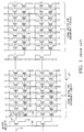
- Fig. 1 is a schematic transistor-level view of a portion of a prior art fully-featured EEPROM core array.
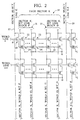
- Fig. 2 is a schematic transistor-level view of a portion of a flash-like EEPROM core organized in accord with the present invention.
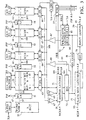
- Fig. 3 is a schematic block-diagram view of the EEPROM device of the present invention incorporating a memory core organized as in Fig. 2 and peripheral logic providing full-featured write access to that core.
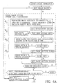
- Figs. 4A-4C are an operational flow chart of a write state machine in accord with the present invention.
- a memory core organization specific to the EEPROM architecture of the present invention divides a memory page, i.e. all storage cells within one row, into 2, 4 or more page sectors 33.
- Each storage cell comprises a cell select transistor 22 serially connected to a variable threshold storage transistor 24.
- the preferred EEPROM architecture uses a 16 bit or 32 bit internal data word architecture while maintaining 8 bit external byte read/write accessibility.
- the new core organization groups the bit lines not by byte or word, but by page sectors 33 with each page sector 33 consisting of multiple data words so that byte select lines and byte select transistors are no longer used.
- the new architecture employs a page sector select line 37 and a page sector select device implemented as a select latch for each page sector 33 and thus reduces or eliminates the use of depletion mode select transistors.
- the fore stated page sector select device may be implemented as a select transistor 40, as shown in Fig. 2.
- the data bits within each page sector 33 are arranged by rank, with bits of equal rank grouped together into blocks. unlike prior art which grouped bits by byte such that each group of bits would consist of one bit of rank 0, one bit of rank 1, one bit of rank 2, and so on up to a bit of rank 7.
- each page sector, 33 consists of thirty-two 16-bit words
- each page sector, 33 will be divided into sixteen bit line blocks, 31, with each bit line block consisting of 32 bits of equal rank.
- all bits of rank 0 within a page sector 33 are grouped contiguously within bit line block 0, 31, all bits of rank 1 within the same page sector 33 are grouped contiguously in bit line block 1, not shown, and so on up to bit line block 15, 35, in the case of a 16 bit wide word organization.
- the new EEPROM architecture also employs an ECC mechanism, 73, Hamming code based, to detect and automatically correct any one bit error per word, 2, 4 or more bytes long, which might have occurred during a read access of the memory core.
- ECC mechanism 73
- Hamming code based Hamming code based
- the use of a multi-byte data architecture greatly reduces the silicon area because the wider the word, the smaller the ratio between the ECC parity bits and the data bits. For example, to correct 1 bit of an 8 bit data word requires 4 parity bits for a bit-wide increase of 50% per data word, a 16 bit data word requires 5 parity bits for an increase of 31%, and a 32 bit data word requires 6 parity bits for an increase of only 19%.
- the present invention has an internal data architecture arranged by multi-byte words, but it communicates with a system user in bytes. As illustrated in Fig. 3, the circuit of the present invention accomplishes this through a series of multiplexing circuits, 75, which select which byte of a multi-byte word is sent out to the system user and de-multiplexing circuit, 79, for accepting byte-size data loaded in from the system user and, by means of a multiple write-clock implementation of the write-cache 83, grouping sequential byte-size data chunks into a multi-byte data word.
- the write cache 83 is the size of one core memory page and is implemented as an SRAM along with all its necessary control logic, such as a finite state machine and counters, to perform a read back cycle of an entire memory page during an erase/write cycle as explained below.
- Programming consists of three cycles; a load cycle, a read back cycle, and a load back cycle.
- the programming cycle begins with a user driven load cycle during which the system user loads new data into the write cache 83.
- the user typically provides the load clock through the WE% pin if CE% is kept low.
- the load clock could be provided through the CE% pin if the WE% pin is kept low.
- the corresponding byte flag of the selected byte address is activated. There are 2, 4 or more byte flags per multi-byte word, but the write cache is byte write-addressable.
- the WE% external clock drives an instruction decoder, not shown, which serves as an interface translating instruction modes from the system user into control signals for a Write State Machine, WSM 77.
- WSM 77 controls the different reading and writing stages of a program and erase cycle as well as the voltages and timings needed to adequately program and erase a cell as explained below.
- the load cycle terminates with a time-out protocol.
- EEPROMS While prior art EEPROMS have an instruction decoder to offer the system user access to the chip's internal functional modes, prior art EEPROMs limit the system user's access to only a few user modes.
- the new EEPROM architecture extends the usage of this instruction decoder to give the system user control of all user modes and test modes.
- the chip possesses an 8 bit mode register which the system user can load with a desired instruction mode ID byte through a software write protect protocol by using a predetermined dedicated sequence.
- the mode register is read by the instruction decoder which communicates the appropriate control signals to the WSM 77 for implementation.
- the WSM 77 Following the load cycle, programming control is transferred to the WSM 77, and it starts by initiating the read back cycle.
- the WSM 77 based on the page address latched at the end of the load cycle, the WSM 77 begins to read data from the corresponding core memory page as defined by a word line 57 into the write cache 83.
- the cache byte flags 85 are used to make sure not to overwrite any new data entered by the system user with the existing data being read from the memory core.
- the WSM 77 monitors an error signal, ERR 111 coming from the ECC unit 73 to detect if the ECC 73 has corrected at least one data word.
- the WSM 77 will set a corresponding programming page sector flag, 47-50, and proceed to program the corrected page sector as determined by one of the page sector sense lines 99-102 thereby refreshing that page sector. In this way the data retention capability of the chip is extended.
- the WSM 77 initiates an erase phase during which the page sectors, as defined by a corresponding page sector sense line 99-102, which have their page sector flag 47-50 activated will be erased. In this way, only the core memory page sectors which received new loaded data or which required the ECC 73 unit to recover lost data are erased.
- the chip will update only the page sectors which satisfy at least one of the following conditions: (1) The user has loaded at least one new byte in the corresponding page sector of the write cache 83; (2) During the read back cycle, the transfer of a page sector from the memory core into the write cache 83 used the ECC 73 to correct at least one error. If none of the page sectors satisfy any of the previously stated conditions, the chip will abort the programming cycle altogether. But if either of the conditions is met, the chip will reprogram only the selected page sectors, thus avoiding unnecessary stress on the core memory page and consequently improving the endurance of the EEPROM as compared to a prior art Flash EEPROM endurance levels.
- the WSM 77 now begins the load back cycle during which it transfers the data from the write cache 83 to the high voltage page sectors 43-46 in preparation of programming the corresponding core memory page sectors.
- the ECC unit 73 generates new parity bits for each data word in the write cache and sends the new parity bits to the high voltage page sectors 43-46, to be written into the memory core along with the data from the write cache.
- the WSM 77 finishes loading the high voltage page sectors 43-46, it applies high programming voltage only to those page sectors which are to be written to as determined by the previously stated conditions. With programming complete, the WSM 77 transfers control back to the address transition detection, ATD, circuit, not shown, which uses the transition of an address to synchronize the memory component's internal clock to the system external clock so that the chip may resume normal read mode.
- a word line 57 coming from the X-Select decoder 55 defines a memory page and is coupled to all word line latch banks, 51-54, and memory sectors 59-62.
- Each memory sector 59-62 consists of a multitude of page sectors with each page sector individually defined by a page sector sense line 99-102.
- a word line latch bank 51-54 is coupled only to its corresponding memory sector 59-62 through its own page sector sense line 99-102.
- word line latch bank "0", 51 is coupled only to page sectors within memory sector "0", 59, through its page sector sense lines 99.
- any combination of word line latch banks 51-54 can be active and thereby raise the page sector sense line of the selected page sector to the internal high programming voltage.
- the byte select transistor of prior art full-featured EEPROM architecture has been replaced by a sector select latch, driven by the page sector flags 47-50 and by the selected word line latch banks 51-54.
- a read cycle which is controlled by the ATD circuit, not shown, data is read by sense amps 67 and 69 through active Y-select pass transistors 63-66. Data bits are read by sense amps 67 and parity bits are read by sense amps 69.
- the master clock signal, "MCLK" 91 goes low and latches an entire word, data plus parity bits, into a master latch register 71.
- the ECC 73 matrix starts evaluating the raw data presented to it by the master latch register outputs.
- the slave clock signal, "SCLK" 93 which is out of phase with MCLK, goes high and lets the ECC outputs into the slave latch multiplexer register 75.
- This register accepts the corrected data word from the ECC outputs and selects only one byte from the multi-byte data word by using the least significant address bits, 95, A0 for a 16-bit-wide word or A1 and A0 for a 32-bit-wide data word.
- the outputs from the slave latch multiplexer register directly drive the chip output buffers 78, which additionally get their enable from the 0E% pin.
- SCLK goes low, thus providing a controlled old data hold time equal to the sensing time of the new data.
- MCLK goes high to let the sense amps 67 and 69 propagate their new outputs into the master latch register.
- the MCLK and SCLK internal clock signals are generated by an address transition detection, ATD, circuit, not shown, which synchronizes the chip read cycle with the system clock. It also protects the chip against the internal power rail noise generated by the high output switching currents.
- the programming instruction begins with a user driven load cycle during which input data from the system user is loaded into a low voltage SRAM write cache 83 instead of being loaded directly into a high voltage page as in prior art.
- the write cache 83 is organized by words 84 plus byte flags 85, but is byte-writable so when the user enters data in bytes, an input demultiplexer 79 presents to the write cache the appropriate byte, as determined by the lower address bits 95, to be arranged into a multi-byte word.
- the write cache distinguishes new data entered by the user from old data read from the memory core by associating a ninth bit, byte flag, to each byte of a word.
- all byte flags are set meaning that at this moment all data in the write cache is trash and can be replaced by data from the core memory when the read back cycle is initiated.
- the byte flag corresponding to the selected byte address inside the page is reset so that these addresses will not be written to from the core memory during the read back cycle.
- the write cache 83 will contain the new loaded data when the load back cycle is initiated and the write cache 83 starts loading its contents to the high voltage page sectors 43-46 in preparation of writing to the core memory.
- Each word line latch bank 51-54 has its own page sector flag 47-50.
- all page sector flags 47-50 are reset meaning that no word line latch bank 51-54, and consequently no page sector, is enabled. If at least one byte is loaded into a page sector of the write cache 83, the corresponding page sector flag 47-50 is set thereby enabling the word line latch bank which controls the corresponding core memory page sector as defined by a page sector sense line 99-102.
- the load cycle is terminated through a time-out period protocol as in prior art.
- the WSM has the capability of driving the internal word address bits in order to sweep the write cache 83 and the selected core memory page through the Y-select pass transistors 63-66.
- Figs. 4A-4C show an operational flow chart of the WSM including the instruction path taken under various instruction modes. For a programming instruction mode, following the load cycle time-out period, the WSM initiates a read back cycle. Each read word-step in the read back cycle has 4 phases as described below.
- the WSM 77 monitors the ECC error signal, ERR 111 as shown in phase 2 of Fig. 4A.
- ECC error signal ERR 111
- the WSM will set the page sector flag 47-50 of the corresponding word line latch bank 51-54 if not already set by the load cycle.
- the WSM 77 now starts an on chip high voltage pump, not shown, and then initiates the erase phase. Only the word line latch banks 51-54 with set page sector flags 47-50 will receive the erasing voltages. The corresponding core memory page sectors get erased. The WSM 77 also polls the on chip timer, not shown, to finish this erase phase. At the end of erase time, the WSM 77 performs an erase recovery, i.e. discharges the high voltage on the selected sense line sector segments.
- the WSM 77 starts the load back cycle. Again it sweeps the word address space and again each load word-step has 4 phases as defined below.
- the WSM 77 initiates the write phase. Again, only word line latch banks 51-54 with set page sector flags 47-50 will send a high programming voltage onto their page sector sense line 99-102. Within each active memory sector 59-62, only the bit lines with set high voltage page latches will actually get the high voltage and thus write to the storage cells on the selected core row. The selected word line 57 also gets the high voltage.
- the WSM 77 polls the on chip timer to finish this write phase. At the end of the write time, the WSM 77 performs a bit line recovery, i.e. discharges the high voltage on the selected bit lines, and then a word line recovery. The WSM 77 now discharges the on chip high voltage pump, and upon exit passes the chip control to the ATD circuitry so that the chip may resume the read mode.
- the circuit of the present invention also implements interruptible load cycles by introducing 3 new bits to the prior art method of polling the write status of a WSM 77. At the beginning of a load cycle, all 3 new status bits are reset and get set at different points during a write cycle as described below.
- the final load can actually be empty.
- the chip will observe the regular load cycle time-out interval and proceed with programming. It is precisely because the final load cycle can be empty, that the final load mode can be interrupted. Since the chip is using the on chip timer to count the load time-out, an interrupt will not prevent the chip from entering programming. In fact, immediately after giving the final load plus programming mode ID, the user system can proceed serving another process.
Landscapes
- Engineering & Computer Science (AREA)
- Theoretical Computer Science (AREA)
- Physics & Mathematics (AREA)
- General Engineering & Computer Science (AREA)
- General Physics & Mathematics (AREA)
- Quality & Reliability (AREA)
- Read Only Memory (AREA)
- Memory System Of A Hierarchy Structure (AREA)
- Techniques For Improving Reliability Of Storages (AREA)
Abstract
Description
- The invention relates to semiconductor electrically erasable read only memories (EEPROMs), particularly to the internal architecture of such devices.
- EEPROMs have the ability to be electrically programmed and erased, and retain their data even after a power supply has been removed. However, they are limited in the number of times each storage cell can be programmed and erased, typically restricted to a few thousand program and erase cycles. An entire memory unit, such as a byte or group of bytes, must endure an erase cycle before new information can be written to any one bit or group of bits in a memory unit.
- Full-featured EEPROMs are those EEPROMs which are part of a memory system with a memory unit size corresponding to one byte of memory cells, and therefore provide write access to a minimum of one byte of memory at a time. This allows limiting their program and erase cycles to only those bytes which need to be changed and thereby increases the endurance of the memory component. The byte accessibility of full-featured EEPROMs also simplifies programming from the user's point of view since one only needs to communicate to the EEPROM the data one wishes to program and the address where the data is to be stored. However, the need to program, erase, and then reprogram each altered byte can require long programming times if the entire chip needs to be reprogrammed. Additionally, because of their more complicated select circuitry, full-featured EEPROMs continue to lag behind other semiconductor memory technologies in terms of density and cost effectiveness. A full-featured EEPROM memory system comprises a core array of storage cells, each cell including a select transistor in series with a variable threshold NMOS transistor. The array is organized into rows and columns with the intersection of a row and column comprising the address location of a storage cell.
- A typical prior art full-featured EEPROM core architecture is presented in Figure 1. A row of memory cells identified by a
dedicated word line 11 electrically coupled to the control gates of all cellselect transistors 21 within one row is equivalent to a memory page in addressable space. Each cell selecttransistor 21 together with a serially connectedvariable threshold transistor 19 constitutes one memory cell capable of storing one bit of information. When aword line 11 is activated, aselect transistor 21 electrically couples its serially connectedvariable threshold transistor 19 to abit line 25 which is used to read the information stored in saidvariable threshold transistor 19. Because of the byte addressability of full-featured EEPROMs, the internal data organization of prior art full-featured EEPROMs was restricted to 8 bits, comprising one byte.
Asense line 15, which applies reading, programming and erasing voltages to the control gate of avariable threshold transistor 19 of a storage cell, is broken into segments coupling together the control gates of 8 consecutive storage variable threshold transistors, or onebyte 27. This data organization necessitates the use of an extra byte select column line, 13, and byte selecttransistor 17 for every byte of memory cells, so that by means of the byte select column lines and the byte select transistors, only one sense line segment and thereby only one byte may be individually selected during programming. The byte selecttransistor 17 requires a relatively large silicon area. Additionally, full-featured EEPROMs usually require some sort of error correction implementation which in order to detect and recover one lost bit of an 8 bit data word requires 4 parity bits for an increase in core memory area of about 50%. The aforestated architectural characteristics of traditional full-featured EEPROMs have so far limited their densities to one megabit. - The advent of flash EEPROMs, offered some answers to the density problems associated with full-featured EEPROMs. Flash EEPROMs utilize one or two transistors per memory cell but do not include byte select column lines and byte select transistors. In this way, flash EEPROMs achieve a more compact design than full-featured EEPROMs, but they are not byte programmable. Flash EEPROMs have minimum write units consisting of blocks or sectors of storage cells. Typically, these blocks comprise one or more rows of the memory array. Flash EEPROMs group their columns by outputs, and not by byte. That is, all bits 0 of all words are adjacent. Flash EEPROMS thus eliminate the byte select lines and the byte select transistors of full-featured EEPROMs and can thereby achieve higher densities. However, the large memory blocks of flash EEPROMs limit the life of the entire chip. In order to reprogram one byte of a memory block, the entire block must first be read to a temporary holding memory, usually a cache, the byte in question is then edited within the holding cache, the entire flash memory block undergoes an erase cycle before the data in the holding cache can be written back to the same flash memory block, thus submitting many memory cells to unnecessary erase/write cycles and making poor use of available system cache space. Additionally, the need for unnecessarily erasing/writing extra bytes can increase the average programming time of a flash chip if only a few bytes need re-programming at a time.
- Some prior art devices have sought to find a compromise between full-featured EEPROMs and flash EEPROMS. U.S. Pat. No. 4,949,309 to Rao offers a chip with both full-featured and flash erase programming modes. This design eliminates the select transistor from traditional EEPROM memory cells in exchange for a more complicated word line decoding scheme, but retains the byte select lines and byte select transistors and incorporates an additional bulk erase line and bulk erase transistor for every pair of word lines. U.S. Pat. No. 5,191,556 to Radjy discloses a method for reducing the size of a flash memory block to a single memory page, one row of memory cells. U.S. Pat. No. 5,317,535 to Talreja discusses an approach for increasing the data format of EEPROMs from 8 bits to 16 bits. U.S. Pat. No. 5,353,248 to Gupta describes an SRAM with backup flash memory of equal size on the same chip. This simplifies programming, but does not make efficient use of the flash memory. U.S. Pat. No. 5,359,569 to Fujita et al. simplifies the programming of flash memory from the user's point of view by incorporating a cache memory and control unit to manage the accessing of multiple flash components at the computer board level.
- It is an object of this invention to provide a method of writing data into an EEPROM while reducing the number of stressful program and erase cycles a memory cell undergoes.
- The invention is defined in
claim 1. - Fig. 1 is a schematic transistor-level view of a portion of a prior art fully-featured EEPROM core array.
- Fig. 2 is a schematic transistor-level view of a portion of a flash-like EEPROM core organized in accord with the present invention.
- Fig. 3 is a schematic block-diagram view of the EEPROM device of the present invention incorporating a memory core organized as in Fig. 2 and peripheral logic providing full-featured write access to that core.
- Figs. 4A-4C are an operational flow chart of a write state machine in accord with the present invention.
- With reference to Fig. 2, a memory core organization specific to the EEPROM architecture of the present invention divides a memory page, i.e. all storage cells within one row, into 2, 4 or
more page sectors 33. Each storage cell comprises a cellselect transistor 22 serially connected to a variablethreshold storage transistor 24. The preferred EEPROM architecture uses a 16 bit or 32 bit internal data word architecture while maintaining 8 bit external byte read/write accessibility. The new core organization groups the bit lines not by byte or word, but bypage sectors 33 with eachpage sector 33 consisting of multiple data words so that byte select lines and byte select transistors are no longer used. Instead, the new architecture employs a page sector selectline 37 and a page sector select device implemented as a select latch for eachpage sector 33 and thus reduces or eliminates the use of depletion mode select transistors. Alternatively, the fore stated page sector select device may be implemented as aselect transistor 40, as shown in Fig. 2. The data bits within eachpage sector 33 are arranged by rank, with bits of equal rank grouped together into blocks. unlike prior art which grouped bits by byte such that each group of bits would consist of one bit of rank 0, one bit ofrank 1, one bit ofrank 2, and so on up to a bit ofrank 7. In the present invention, if each page sector, 33, consists of thirty-two 16-bit words, then each page sector, 33, will be divided into sixteen bit line blocks, 31, with each bit line block consisting of 32 bits of equal rank. For example, all bits of rank 0 within apage sector 33 are grouped contiguously withinbit line block 0, 31, all bits ofrank 1 within thesame page sector 33 are grouped contiguously inbit line block 1, not shown, and so on up tobit line block - With reference to Fig. 3, the new EEPROM architecture also employs an ECC mechanism, 73, Hamming code based, to detect and automatically correct any one bit error per word, 2, 4 or more bytes long, which might have occurred during a read access of the memory core. The use of a multi-byte data architecture greatly reduces the silicon area because the wider the word, the smaller the ratio between the ECC parity bits and the data bits. For example, to correct 1 bit of an 8 bit data word requires 4 parity bits for a bit-wide increase of 50% per data word, a 16 bit data word requires 5 parity bits for an increase of 31%, and a 32 bit data word requires 6 parity bits for an increase of only 19%.
- The present invention has an internal data architecture arranged by multi-byte words, but it communicates with a system user in bytes. As illustrated in Fig. 3, the circuit of the present invention accomplishes this through a series of multiplexing circuits, 75, which select which byte of a multi-byte word is sent out to the system user and de-multiplexing circuit, 79, for accepting byte-size data loaded in from the system user and, by means of a multiple write-clock implementation of the write-
cache 83, grouping sequential byte-size data chunks into a multi-byte data word. Thewrite cache 83 is the size of one core memory page and is implemented as an SRAM along with all its necessary control logic, such as a finite state machine and counters, to perform a read back cycle of an entire memory page during an erase/write cycle as explained below. - Programming consists of three cycles; a load cycle, a read back cycle, and a load back cycle. The programming cycle begins with a user driven load cycle during which the system user loads new data into the
write cache 83. As with prior art EEPROMS, the user typically provides the load clock through the WE% pin if CE% is kept low. Alternatively, the load clock could be provided through the CE% pin if the WE% pin is kept low. At each load cycle, the corresponding byte flag of the selected byte address is activated. There are 2, 4 or more byte flags per multi-byte word, but the write cache is byte write-addressable. The WE% external clock drives an instruction decoder, not shown, which serves as an interface translating instruction modes from the system user into control signals for a Write State Machine,WSM 77. TheWrite State Machine 77 in turn controls the different reading and writing stages of a program and erase cycle as well as the voltages and timings needed to adequately program and erase a cell as explained below. As in prior art memory loads, the load cycle terminates with a time-out protocol. - While prior art EEPROMS have an instruction decoder to offer the system user access to the chip's internal functional modes, prior art EEPROMs limit the system user's access to only a few user modes. The new EEPROM architecture extends the usage of this instruction decoder to give the system user control of all user modes and test modes. The chip possesses an 8 bit mode register which the system user can load with a desired instruction mode ID byte through a software write protect protocol by using a predetermined dedicated sequence. The mode register is read by the instruction decoder which communicates the appropriate control signals to the
WSM 77 for implementation. - Following the load cycle, programming control is transferred to the
WSM 77, and it starts by initiating the read back cycle. During the read back cycle, based on the page address latched at the end of the load cycle, theWSM 77 begins to read data from the corresponding core memory page as defined by aword line 57 into thewrite cache 83. The cache byte flags 85 are used to make sure not to overwrite any new data entered by the system user with the existing data being read from the memory core. During the read back cycle of a core memory page, theWSM 77 monitors an error signal,ERR 111 coming from theECC unit 73 to detect if theECC 73 has corrected at least one data word. If theECC 73 has indeed corrected a data word then even if the user has not loaded any new data into thewrite cache 83, theWSM 77 will set a corresponding programming page sector flag, 47-50, and proceed to program the corrected page sector as determined by one of the page sector sense lines 99-102 thereby refreshing that page sector. In this way the data retention capability of the chip is extended. Once the core memory page has been written to thewrite cache 83, theWSM 77 initiates an erase phase during which the page sectors, as defined by a corresponding page sector sense line 99-102, which have their page sector flag 47-50 activated will be erased. In this way, only the core memory page sectors which received new loaded data or which required theECC 73 unit to recover lost data are erased. Therefore the chip will update only the page sectors which satisfy at least one of the following conditions: (1) The user has loaded at least one new byte in the corresponding page sector of thewrite cache 83; (2) During the read back cycle, the transfer of a page sector from the memory core into thewrite cache 83 used theECC 73 to correct at least one error. If none of the page sectors satisfy any of the previously stated conditions, the chip will abort the programming cycle altogether. But if either of the conditions is met, the chip will reprogram only the selected page sectors, thus avoiding unnecessary stress on the core memory page and consequently improving the endurance of the EEPROM as compared to a prior art Flash EEPROM endurance levels. - The
WSM 77 now begins the load back cycle during which it transfers the data from thewrite cache 83 to the high voltage page sectors 43-46 in preparation of programming the corresponding core memory page sectors. During the load back cycle, theECC unit 73 generates new parity bits for each data word in the write cache and sends the new parity bits to the high voltage page sectors 43-46, to be written into the memory core along with the data from the write cache. Once theWSM 77 finishes loading the high voltage page sectors 43-46, it applies high programming voltage only to those page sectors which are to be written to as determined by the previously stated conditions. With programming complete, theWSM 77 transfers control back to the address transition detection, ATD, circuit, not shown, which uses the transition of an address to synchronize the memory component's internal clock to the system external clock so that the chip may resume normal read mode. - With reference to Fig. 3, the memory core is segmented according to the memory page segmentation. A
word line 57 coming from theX-Select decoder 55 defines a memory page and is coupled to all word line latch banks, 51-54, and memory sectors 59-62. Each memory sector 59-62 consists of a multitude of page sectors with each page sector individually defined by a page sector sense line 99-102. A word line latch bank 51-54 is coupled only to its corresponding memory sector 59-62 through its own page sector sense line 99-102. For example, word line latch bank "0", 51, is coupled only to page sectors within memory sector "0", 59, through its page sector sense lines 99. In normal programming, any combination of word line latch banks 51-54 can be active and thereby raise the page sector sense line of the selected page sector to the internal high programming voltage. The byte select transistor of prior art full-featured EEPROM architecture has been replaced by a sector select latch, driven by the page sector flags 47-50 and by the selected word line latch banks 51-54. - Above the memory core there are the high voltage page sectors 43-46, a row of latches which selectively can raise the bit lines to the internal high voltage level.
- Below the memory core is the new architecture developed to control the data path necessary during a normal read cycle, read back cycle, load cycle, and load back cycle. The architecture can best be explained by discussing the data path of a normal read cycle and a program instruction.
- During a read cycle, which is controlled by the ATD circuit, not shown, data is read by
sense amps sense amps 67 and parity bits are read bysense amps 69. When the sensing time is up, the master clock signal, "MCLK" 91, goes low and latches an entire word, data plus parity bits, into amaster latch register 71. At the latest, beginning with the high to low MCLK transition, theECC 73 matrix starts evaluating the raw data presented to it by the master latch register outputs. The slave clock signal, "SCLK" 93, which is out of phase with MCLK, goes high and lets the ECC outputs into the slavelatch multiplexer register 75. This register accepts the corrected data word from the ECC outputs and selects only one byte from the multi-byte data word by using the least significant address bits, 95, A0 for a 16-bit-wide word or A1 and A0 for a 32-bit-wide data word. The outputs from the slave latch multiplexer register directly drive the chip output buffers 78, which additionally get their enable from the 0E% pin. At the next address change detected by the ATD circuit, SCLK goes low, thus providing a controlled old data hold time equal to the sensing time of the new data. MCLK goes high to let thesense amps - The MCLK and SCLK internal clock signals are generated by an address transition detection, ATD, circuit, not shown, which synchronizes the chip read cycle with the system clock. It also protects the chip against the internal power rail noise generated by the high output switching currents.
- The programming instruction begins with a user driven load cycle during which input data from the system user is loaded into a low voltage
SRAM write cache 83 instead of being loaded directly into a high voltage page as in prior art. Thewrite cache 83 is organized bywords 84 plus byte flags 85, but is byte-writable so when the user enters data in bytes, aninput demultiplexer 79 presents to the write cache the appropriate byte, as determined by thelower address bits 95, to be arranged into a multi-byte word. The write cache distinguishes new data entered by the user from old data read from the memory core by associating a ninth bit, byte flag, to each byte of a word. At the beginning of a load cycle, for example, all byte flags are set meaning that at this moment all data in the write cache is trash and can be replaced by data from the core memory when the read back cycle is initiated. With each load access made by the system user, the byte flag corresponding to the selected byte address inside the page is reset so that these addresses will not be written to from the core memory during the read back cycle. Thus thewrite cache 83 will contain the new loaded data when the load back cycle is initiated and thewrite cache 83 starts loading its contents to the high voltage page sectors 43-46 in preparation of writing to the core memory. - Each word line latch bank 51-54 has its own page sector flag 47-50. At the beginning of a load cycle, all page sector flags 47-50 are reset meaning that no word line latch bank 51-54, and consequently no page sector, is enabled. If at least one byte is loaded into a page sector of the
write cache 83, the corresponding page sector flag 47-50 is set thereby enabling the word line latch bank which controls the corresponding core memory page sector as defined by a page sector sense line 99-102. The load cycle is terminated through a time-out period protocol as in prior art. - From this moment, the programming control belongs to the
write state machine 77. The WSM has the capability of driving the internal word address bits in order to sweep thewrite cache 83 and the selected core memory page through the Y-select pass transistors 63-66. Figs. 4A-4C show an operational flow chart of the WSM including the instruction path taken under various instruction modes. For a programming instruction mode, following the load cycle time-out period, the WSM initiates a read back cycle. Each read word-step in the read back cycle has 4 phases as described below. - Phase 1: The SRAM columns are equalized at about VCC/2.
It is during this equalization time that the
WSM 77 may change the word addresses without upsetting the SRAM content. With an updated word address, the core is accessed by the data senseamps 67 and by theparity sense amps 69 and old raw data plus parity bits are presented to theECC circuit 73. - Phase 2: When the
ECC 73 has completed error correction, it will have valid data on its outputs and a set error signal,ERR 111, if the raw data had to be corrected. At the same time, the SRAM latches the byte flags onto its outputs and will maintain them latched until the next word-step. - Phase 3: The read back, RB,
gate 81 connects theECC 73 outputs to thewrite cache 83 inputs while theWSM 77 evaluates the byte flags. - Phase 4: Each byte in a word has its own SRAM write
clock signal, not shown, which arrives from the
WSM 77 only if the corresponding byte flag has been read as set during the previous phase. If the byte flag has been read as reset, meaning that this location contains newly loaded data, the write cache SRAM will not receive a write clock for the corresponding byte, so the new loaded data will be preserved in the write cache. -
- During the entire read back cycle, the
WSM 77 monitors the ECC error signal,ERR 111 as shown inphase 2 of Fig. 4A. When a word is read back with the usage of theECC 73 to correct it, theERR 111 signal is set and the WSM will set the page sector flag 47-50 of the corresponding word line latch bank 51-54 if not already set by the load cycle. - The
WSM 77 now starts an on chip high voltage pump, not shown, and then initiates the erase phase. Only the word line latch banks 51-54 with set page sector flags 47-50 will receive the erasing voltages. The corresponding core memory page sectors get erased. TheWSM 77 also polls the on chip timer, not shown, to finish this erase phase. At the end of erase time, theWSM 77 performs an erase recovery, i.e. discharges the high voltage on the selected sense line sector segments. - Next, the
WSM 77 starts the load back cycle. Again it sweeps the word address space and again each load word-step has 4 phases as defined below. - Phase 1: The SRAM columns are equalized at about VCC/2. It is during this equalization time that the WSM may change the word addresses without upsetting the SRAM content.
- Phase 2: The SRAM sense amps, not shown, read the new data, which until the next word-step will stay latched on the SRAM outputs, 87.
- Phase 3: The
ECC 73 is switched into parity generating mode, and its inputs are connected to the SRAM outputs 87 through the data bus, 107. This multiplexing function is delivered by themaster latch register 71, which has dual inputs controlled by the read backsignal RB 103 and the load backsignal LB 104. Both RB and LB are controlled by the WSM. At the end ofPhase 3, theECC 73output parity bits 89 are ready, and present the valid new parity information ontobus 109 to be written together with the SRAM data bits, 87. - Phase 4: The
SRAM output buffers 87drive bus 107 and the ECC parity output buffers 89drive bus 109, which writes the new word into the high voltage page sectors 43-46 through the appropriate Y-select pass transistors 63-66 and core bit lines. -
- The
WSM 77 initiates the write phase. Again, only word line latch banks 51-54 with set page sector flags 47-50 will send a high programming voltage onto their page sector sense line 99-102. Within each active memory sector 59-62, only the bit lines with set high voltage page latches will actually get the high voltage and thus write to the storage cells on the selected core row. The selectedword line 57 also gets the high voltage. TheWSM 77 polls the on chip timer to finish this write phase. At the end of the write time, theWSM 77 performs a bit line recovery, i.e. discharges the high voltage on the selected bit lines, and then a word line recovery. TheWSM 77 now discharges the on chip high voltage pump, and upon exit passes the chip control to the ATD circuitry so that the chip may resume the read mode. - The circuit of the present invention also implements interruptible load cycles by introducing 3 new bits to the prior art method of polling the write status of a
WSM 77. At the beginning of a load cycle, all 3 new status bits are reset and get set at different points during a write cycle as described below. - Bit: LOAD TIME-OUT WARNING ― Is set after 75% of the total time-out period of a load cycle has expired, and remains set until the exit of the WSM.
- Bit: ERASE ACTIVE ― Is set during the read back and erase phases.
- Bit: WRITE ACTIVE ― Is set during the load back and write phases.
-
- A typical interruptible load cycle would follow this flow:
- Part 1: The user system initiates a write cache clear
plus load only cycle by loading a mode ID which clears
the write cache SRAM and tells the chip not to proceed
with the core updating upon completion of the load cycle.
If during this load cycle, a higher priority interrupt
request arrives, the user system can safely grant the
interrupt request and postpone this load cycle. Upon
exit of the other process, the user system should use the
status query capability as follows:
- Check if the toggle bit is still active, meaning that the WSM is still active, by successive read cycles at the same address. If the toggle bit is toggling, then the user system should check the LOAD TIME-OUT WARNING bit. If it is still reset, then the user system still has at least 25% of the total load cycle time-out period to finish loading data, and so can safely resume the Load cycle. If the toggle bit is toggling but the LOAD TIME-OUT WARNING bit is already set, than the user system should let the chip complete the time-out interval and attempt to resume loading after the toggle bit ceases toggling indicating that the WSM is no longer active.
- If the toggle bit is no longer active, then
the user system can proceed with
part 2.
- Part 2: A Load Only should be loaded as mode ID to continue the loading cycle with the interrupt capability. The handshake provided by the status query should be used as described above.
- Part 3: Upon completion of the load cycle, i.e. when despite all interrupts the user system has managed to load all the new bytes in the selected page, or when the user system can disable all higher priority interrupts, a final load plus programming mode ID can be given to the chip to let it update the core with the new data loaded in the write cache.
-
- The final load can actually be empty. The chip will observe the regular load cycle time-out interval and proceed with programming. It is precisely because the final load cycle can be empty, that the final load mode can be interrupted. Since the chip is using the on chip timer to count the load time-out, an interrupt will not prevent the chip from entering programming. In fact, immediately after giving the final load plus programming mode ID, the user system can proceed serving another process.
Claims (11)
- A method of writing data into an EEPROM memory array of the type having a main memory core divided into a plurality of memory pages and a write cache using three cycles characterized by:(a) user input of byte-size data into said write cache;(b) reading back multi-byte data words from a selected main memory page into the write cache; and(c) loading back multi-byte data words from the write cache into the main memory core.
- The method of claim 1 wherein up to a memory page of byte-size data units is sequentially loaded into the write cache during the user input cycle and a cache flag bit is activated for each new byte-size data unit entered into the write cache.
- The method of claim 1 wherein said user input cycle is selectively interrupted without affecting said reading back and loading back cycles by utilizing two loading modes including a first Load Only mode for initiating a load-time-out period during which a user enters data without proceeding to the reading back cycle, and a second Final Load and Program mode used for proceeding to the read back cycle after the user has finished entering data and optionally proceeding directly to the reading back cycle without the need for the user to enter data;
said user input cycle being selectively interrupted by initiating the following sequence;(a) upon initiating a Load Only mode, if during loading an interrupt is received then leaving the loading cycle and addressing said interrupt;(b) upon returning from addressing said interrupt, verifying that said Load Only mode is still active and if not active then initiating another Load Only sequence, else if still active then determining if a specified amount of said load time-out period has not expired and if it has not expired then resuming loading at the point where the interrupt was received, else if more than the specified amount of the load time-out period has expired then waiting for the load time-out period to expire after which all previously entered data will be discarded and re-initiating another Load Only cycle; and(c) upon finishing loading, asserting a Final Load and Program mode and thereby allowing the initiation of the reading back cycle without the need for entering new data. - The method of claim 1 wherein each reading back cycle has four phases characterized by:(a) disabling the write cache while issuing an address of a multi-byte data word to be read from a memory sector within said memory page, with the multi-byte data word being presented to an error correction circuit;(b) issuing a valid error bit signal if the multi-byte data word had to be corrected, and if the multi-byte data word had to be corrected then targeting the memory sector from which the multi-byte data word was read for an erase and re-program sequence at the end of said reading back cycle in order to refresh the corrupted memory sector;(c) directing outputs from the error correction circuit to write cache inputs, with evaluation of the cache flag bits to determine if the write cache contains user input data at the selected address; and(d) if the cache flag bits are not activated indicating that no user input data exists at the selected address then enabling the write cache to receive a write signal for the directed outputs from said error correction circuit, else if the cache flag bit is activated then disabling the write cache from receiving a write signal whereupon said directed outputs from the error correction circuit will not be written into the write cache.
- The method of claim 4 wherein an entire main memory page of multi-byte data words are read during a reading back cycle.
- The method of claim 4 wherein said directing of outputs from the error correction circuit to the write cache inputs involves dividing a multi-byte data word into individual byte-size data units and sequentially directing each byte-size data unit of a multi-byte data word to the write cache inputs.
- The method of claim 4 wherein at the end of a reading back cycle, erasing is initiated to erase the memory sectors with addresses corresponding to new data written into the write cache as determined by the cache flag bits and with addresses corresponding to corrected multi-byte data words as determined by said valid error bit signal.
- The method of claim 1 wherein each loading back cycle has four phases characterized by:(a) disabling the write cache and issuing an cache address corresponding to data to be written into the main memory core;(b) enabling the write cache and outputting the contents therefrom of said cache address;(c) directing said write cache contents to a parity generating circuit for generating parity bits corresponding to said write cache contents; and(d) programming said write cache contents and parity bits into selected memory sectors of the main memory core.
- The method of claim 8 wherein an entire selected main memory core page is read during a reading back cycle and said write cache contents and parity bits are written into said main memory core at a memory location determined by a combination of said cache address and said selected main memory core page.
- The method of claim 8 wherein said parity generating circuit combines said write cache contents into a multi-byte word before generating said parity bits.
- The method of claim 8 wherein said selected memory sectors are determined by a combination of the address of user input data written into said write cache during said user input cycle and the address of any lost data during said reading back data cycle.
Priority Applications (1)
| Application Number | Priority Date | Filing Date | Title |
|---|---|---|---|
| EP01117713A EP1158533B1 (en) | 1995-03-17 | 1996-02-22 | Eeprom array with flash-like core |
Applications Claiming Priority (3)
| Application Number | Priority Date | Filing Date | Title |
|---|---|---|---|
| US08/405,884 US5606532A (en) | 1995-03-17 | 1995-03-17 | EEPROM array with flash-like core |
| US405884 | 1995-03-17 | ||
| PCT/US1996/002482 WO1996029704A1 (en) | 1995-03-17 | 1996-02-22 | Eeprom array with flash-like core |
Related Child Applications (1)
| Application Number | Title | Priority Date | Filing Date |
|---|---|---|---|
| EP01117713A Division EP1158533B1 (en) | 1995-03-17 | 1996-02-22 | Eeprom array with flash-like core |
Publications (3)
| Publication Number | Publication Date |
|---|---|
| EP0764330A1 EP0764330A1 (en) | 1997-03-26 |
| EP0764330A4 EP0764330A4 (en) | 2000-07-19 |
| EP0764330B1 true EP0764330B1 (en) | 2002-05-15 |
Family
ID=23605633
Family Applications (2)
| Application Number | Title | Priority Date | Filing Date |
|---|---|---|---|
| EP01117713A Expired - Lifetime EP1158533B1 (en) | 1995-03-17 | 1996-02-22 | Eeprom array with flash-like core |
| EP96907103A Expired - Lifetime EP0764330B1 (en) | 1995-03-17 | 1996-02-22 | Eeprom array with flash-like core |
Family Applications Before (1)
| Application Number | Title | Priority Date | Filing Date |
|---|---|---|---|
| EP01117713A Expired - Lifetime EP1158533B1 (en) | 1995-03-17 | 1996-02-22 | Eeprom array with flash-like core |
Country Status (8)
| Country | Link |
|---|---|
| US (2) | US5606532A (en) |
| EP (2) | EP1158533B1 (en) |
| JP (1) | JPH10500801A (en) |
| KR (1) | KR100348774B1 (en) |
| CN (2) | CN1110053C (en) |
| DE (2) | DE69621201T2 (en) |
| TW (1) | TW309616B (en) |
| WO (1) | WO1996029704A1 (en) |
Families Citing this family (174)
| Publication number | Priority date | Publication date | Assignee | Title |
|---|---|---|---|---|
| EP0617363B1 (en) * | 1989-04-13 | 2000-01-26 | SanDisk Corporation | Defective cell substitution in EEprom array |
| US5430859A (en) * | 1991-07-26 | 1995-07-04 | Sundisk Corporation | Solid state memory system including plural memory chips and a serialized bus |
| US5673417A (en) * | 1995-07-20 | 1997-09-30 | Inventec Corporation | Electronic organizer with a flash memory and associated data archiving |
| JP3941149B2 (en) * | 1996-12-03 | 2007-07-04 | ソニー株式会社 | Semiconductor nonvolatile memory device |
| KR100200922B1 (en) * | 1995-12-27 | 1999-06-15 | 윤종용 | Pumping voltage generator of semiconductor memory device |
| US5890192A (en) * | 1996-11-05 | 1999-03-30 | Sandisk Corporation | Concurrent write of multiple chunks of data into multiple subarrays of flash EEPROM |
| JP3411186B2 (en) * | 1997-06-06 | 2003-05-26 | シャープ株式会社 | Nonvolatile semiconductor memory device |
| DE19731954C2 (en) * | 1997-07-24 | 2000-08-24 | Bosch Gmbh Robert | Method for the detection of incorrectly programmed memory cells of a memory |
| US5930167A (en) * | 1997-07-30 | 1999-07-27 | Sandisk Corporation | Multi-state non-volatile flash memory capable of being its own two state write cache |
| TW337607B (en) | 1997-08-06 | 1998-08-01 | Mos Electronics Taiwan Inc | Process for forming a contact hole in an EEPROM with NOR construction |
| US6040216A (en) * | 1997-08-11 | 2000-03-21 | Mosel Vitelic, Inc. | Method (and device) for producing tunnel silicon oxynitride layer |
| US6000006A (en) * | 1997-08-25 | 1999-12-07 | Bit Microsystems, Inc. | Unified re-map and cache-index table with dual write-counters for wear-leveling of non-volatile flash RAM mass storage |
| JPH11176158A (en) * | 1997-12-10 | 1999-07-02 | Fujitsu Ltd | Latch circuit, data output circuit, and semiconductor device with it |
| TW425660B (en) | 1997-12-12 | 2001-03-11 | Mosel Vitelic Inc | Method of forming uniform dielectric layer between two conductive layers in integrated circuit |
| TW374939B (en) | 1997-12-19 | 1999-11-21 | Promos Technologies Inc | Method of formation of 2 gate oxide layers of different thickness in an IC |
| KR100266748B1 (en) * | 1997-12-31 | 2000-10-02 | 윤종용 | Semiconductor memory device and error correction method thereof |
| TW382801B (en) | 1998-02-25 | 2000-02-21 | Mosel Vitelic Inc | Method of forming two transistors having different threshold voltage in integrated circuit |
| TW480713B (en) * | 1998-03-03 | 2002-03-21 | Mosel Vitelic Inc | Method for forming different thickness of field oxide in integrated circuit and the structure of the same |
| US6136653A (en) | 1998-05-11 | 2000-10-24 | Mosel Vitelic, Inc. | Method and device for producing undercut gate for flash memory |
| US6261903B1 (en) | 1998-05-14 | 2001-07-17 | Mosel Vitelic, Inc. | Floating gate method and device |
| US6365455B1 (en) | 1998-06-05 | 2002-04-02 | Mosel Vitelic, Inc. | Flash memory process using polysilicon spacers |
| KR20010053128A (en) * | 1998-06-24 | 2001-06-25 | 인피니언 테크놀로지스 아게 | Electronic test memory device |
| JP3999900B2 (en) | 1998-09-10 | 2007-10-31 | 株式会社東芝 | Nonvolatile semiconductor memory |
| US6088268A (en) * | 1998-09-17 | 2000-07-11 | Atmel Corporation | Flash memory array with internal refresh |
| JP4074029B2 (en) | 1999-06-28 | 2008-04-09 | 株式会社東芝 | Flash memory |
| FR2798767B1 (en) * | 1999-09-16 | 2001-12-14 | St Microelectronics Sa | METHOD FOR WRITING IN PAGE MODE OF AN ELECTRICALLY PROGRAMMABLE / ERASABLE NON-VOLATILE MEMORY AND CORRESPONDING ARCHITECTURE |
| FR2802012B1 (en) | 1999-12-07 | 2002-02-15 | St Microelectronics Sa | FAST DRAM MEMORY |
| US6728913B1 (en) * | 2000-02-25 | 2004-04-27 | Advanced Micro Devices, Inc. | Data recycling in memory |
| US6731538B2 (en) * | 2000-03-10 | 2004-05-04 | Kabushiki Kaisha Toshiba | Semiconductor memory device including page latch circuit |
| JP2001297038A (en) | 2000-04-11 | 2001-10-26 | Toshiba Corp | Data storage device, recording medium, and recording medium control method |
| US6400603B1 (en) | 2000-05-03 | 2002-06-04 | Advanced Technology Materials, Inc. | Electronically-eraseable programmable read-only memory having reduced-page-size program and erase |
| US6950336B2 (en) * | 2000-05-03 | 2005-09-27 | Emosyn America, Inc. | Method and apparatus for emulating an electrically erasable programmable read only memory (EEPROM) using non-volatile floating gate memory cells |
| FR2809222A1 (en) * | 2000-05-17 | 2001-11-23 | St Microelectronics Sa | EEPROM MEMORY COMPRISING AN ERROR CORRECTION SYSTEM |
| DE60129294D1 (en) * | 2001-02-19 | 2007-08-23 | St Microelectronics Srl | A method for refreshing the stored data in an electrically erasable and programmable nonvolatile memory |
| JP4530562B2 (en) * | 2001-03-27 | 2010-08-25 | ローム株式会社 | Non-volatile memory |
| US6456528B1 (en) | 2001-09-17 | 2002-09-24 | Sandisk Corporation | Selective operation of a multi-state non-volatile memory system in a binary mode |
| US6717847B2 (en) * | 2001-09-17 | 2004-04-06 | Sandisk Corporation | Selective operation of a multi-state non-volatile memory system in a binary mode |
| US6683817B2 (en) * | 2002-02-21 | 2004-01-27 | Qualcomm, Incorporated | Direct memory swapping between NAND flash and SRAM with error correction coding |
| US6751127B1 (en) | 2002-04-24 | 2004-06-15 | Macronix International, Co. Ltd. | Systems and methods for refreshing non-volatile memory |
| US6633500B1 (en) | 2002-04-26 | 2003-10-14 | Macronix International Co., Ltd. | Systems and methods for refreshing a non-volatile memory using a token |
| JP4257824B2 (en) * | 2002-07-03 | 2009-04-22 | シャープ株式会社 | Semiconductor memory device |
| US7061792B1 (en) * | 2002-08-10 | 2006-06-13 | National Semiconductor Corporation | Low AC power SRAM architecture |
| US20040153902A1 (en) * | 2003-01-21 | 2004-08-05 | Nexflash Technologies, Inc. | Serial flash integrated circuit having error detection and correction |
| US6996688B2 (en) * | 2003-03-11 | 2006-02-07 | International Business Machines Corporation | Method, system, and program for improved throughput in remote mirroring systems |
| CN1311366C (en) * | 2003-05-22 | 2007-04-18 | 群联电子股份有限公司 | Parallel double-track using method for quick flashing storage |
| DE60322387D1 (en) * | 2003-08-27 | 2008-09-04 | Advanced Risc Mach Ltd | Apparatus and method for managing transactions for writing and reading to EEPROM memory or flash memory |
| US7640370B1 (en) * | 2003-11-25 | 2009-12-29 | Marvell International Ltd. | Method and apparatus for controlling data transfer between EEPROM and a physical layer device |
| US7173863B2 (en) * | 2004-03-08 | 2007-02-06 | Sandisk Corporation | Flash controller cache architecture |
| US7099221B2 (en) * | 2004-05-06 | 2006-08-29 | Micron Technology, Inc. | Memory controller method and system compensating for memory cell data losses |
| JP4135680B2 (en) * | 2004-05-31 | 2008-08-20 | ソニー株式会社 | Semiconductor memory device and signal processing system |
| US20060010339A1 (en) * | 2004-06-24 | 2006-01-12 | Klein Dean A | Memory system and method having selective ECC during low power refresh |
| US7340668B2 (en) * | 2004-06-25 | 2008-03-04 | Micron Technology, Inc. | Low power cost-effective ECC memory system and method |
| US7116602B2 (en) | 2004-07-15 | 2006-10-03 | Micron Technology, Inc. | Method and system for controlling refresh to avoid memory cell data losses |
| US6965537B1 (en) | 2004-08-31 | 2005-11-15 | Micron Technology, Inc. | Memory system and method using ECC to achieve low power refresh |
| US7882299B2 (en) * | 2004-12-21 | 2011-02-01 | Sandisk Corporation | System and method for use of on-chip non-volatile memory write cache |
| US7212440B2 (en) * | 2004-12-30 | 2007-05-01 | Sandisk Corporation | On-chip data grouping and alignment |
| TWI263229B (en) * | 2005-03-17 | 2006-10-01 | Sunplus Technology Co Ltd | Memory device with interface for serial transmission and error correction method for serial transmission interface |
| KR100680473B1 (en) * | 2005-04-11 | 2007-02-08 | 주식회사 하이닉스반도체 | Flash memory device with reduced access time |
| JP4761910B2 (en) * | 2005-10-05 | 2011-08-31 | 株式会社東芝 | Nonvolatile semiconductor memory device and nonvolatile memory system using the same |
| JP4910360B2 (en) * | 2005-10-20 | 2012-04-04 | ソニー株式会社 | Storage device, computer system, and data writing method |
| US7447096B2 (en) * | 2006-05-05 | 2008-11-04 | Honeywell International Inc. | Method for refreshing a non-volatile memory |
| US8077516B2 (en) * | 2006-05-08 | 2011-12-13 | Macronix International Co., Ltd. | Method and apparatus for accessing memory with read error by changing comparison |
| US7773421B2 (en) * | 2006-05-08 | 2010-08-10 | Macronix International Co., Ltd. | Method and apparatus for accessing memory with read error by changing comparison |
| US7471562B2 (en) * | 2006-05-08 | 2008-12-30 | Macronix International Co., Ltd. | Method and apparatus for accessing nonvolatile memory with read error by changing read reference |
| US8997255B2 (en) | 2006-07-31 | 2015-03-31 | Inside Secure | Verifying data integrity in a data storage device |
| US7567461B2 (en) * | 2006-08-18 | 2009-07-28 | Micron Technology, Inc. | Method and system for minimizing number of programming pulses used to program rows of non-volatile memory cells |
| US8352752B2 (en) * | 2006-09-01 | 2013-01-08 | Inside Secure | Detecting radiation-based attacks |
| US7894289B2 (en) | 2006-10-11 | 2011-02-22 | Micron Technology, Inc. | Memory system and method using partial ECC to achieve low power refresh and fast access to data |
| US7900120B2 (en) | 2006-10-18 | 2011-03-01 | Micron Technology, Inc. | Memory system and method using ECC with flag bit to identify modified data |
| EP2092530B1 (en) * | 2006-12-07 | 2012-10-31 | Nxp B.V. | Method and device for reconfiguration of reliability data in flash eeprom storage pages |
| JP5018074B2 (en) * | 2006-12-22 | 2012-09-05 | 富士通セミコンダクター株式会社 | Memory device, memory controller and memory system |
| KR100819102B1 (en) | 2007-02-06 | 2008-04-03 | 삼성전자주식회사 | Non-volatile semiconductor memory device with advanced multi page program operation |
| KR100914265B1 (en) * | 2007-05-10 | 2009-08-27 | 삼성전자주식회사 | Nonvolatile memory device, memory system thereof, and reading method thereof |
| KR100888482B1 (en) | 2007-05-11 | 2009-03-12 | 삼성전자주식회사 | Nonvolatile semi-conductor memory device and wirte operation method of the nonvolatile semi-conductor memory device |
| KR101472797B1 (en) * | 2007-07-16 | 2014-12-15 | 삼성전자주식회사 | Method and apparatus for reading or writing data |
| KR101425957B1 (en) * | 2007-08-21 | 2014-08-06 | 삼성전자주식회사 | Ecc control circuit and multi channel memory system icluding the same |
| JP2009104757A (en) * | 2007-10-02 | 2009-05-14 | Panasonic Corp | Semiconductor storage device |
| JP5049733B2 (en) | 2007-10-17 | 2012-10-17 | 株式会社東芝 | Information processing system |
| US8959307B1 (en) | 2007-11-16 | 2015-02-17 | Bitmicro Networks, Inc. | Reduced latency memory read transactions in storage devices |
| US7978516B2 (en) | 2007-12-27 | 2011-07-12 | Pliant Technology, Inc. | Flash memory controller having reduced pinout |
| KR101483190B1 (en) * | 2008-09-05 | 2015-01-19 | 삼성전자주식회사 | Memory system and data processing method thereof |
| EP2267724A1 (en) * | 2009-06-26 | 2010-12-29 | STMicroelectronics Rousset SAS | EEPROM memory architecture optimised for embedded memories |
| US8665601B1 (en) | 2009-09-04 | 2014-03-04 | Bitmicro Networks, Inc. | Solid state drive with improved enclosure assembly |
| US9135190B1 (en) | 2009-09-04 | 2015-09-15 | Bitmicro Networks, Inc. | Multi-profile memory controller for computing devices |
| US8447908B2 (en) | 2009-09-07 | 2013-05-21 | Bitmicro Networks, Inc. | Multilevel memory bus system for solid-state mass storage |
| US8560804B2 (en) | 2009-09-14 | 2013-10-15 | Bitmicro Networks, Inc. | Reducing erase cycles in an electronic storage device that uses at least one erase-limited memory device |
| WO2011067795A1 (en) * | 2009-12-02 | 2011-06-09 | Ferdinando Bedeschi | Refresh architecture and algorithm for non-volatile memories |
| US20120246384A1 (en) * | 2011-03-21 | 2012-09-27 | Winbond Electronics Corp. | Flash memory and flash memory accessing method |
| CN102339644B (en) * | 2011-07-27 | 2014-12-24 | 聚辰半导体(上海)有限公司 | Memorizer and operating method thereof |
| US9372755B1 (en) | 2011-10-05 | 2016-06-21 | Bitmicro Networks, Inc. | Adaptive power cycle sequences for data recovery |
| US9058289B2 (en) * | 2011-11-07 | 2015-06-16 | Sandisk Enterprise Ip Llc | Soft information generation for memory systems |
| EP2608036A1 (en) * | 2011-12-22 | 2013-06-26 | Thomson Licensing | Method and system for managing error detection and correction |
| US9043669B1 (en) | 2012-05-18 | 2015-05-26 | Bitmicro Networks, Inc. | Distributed ECC engine for storage media |
| CN102768859A (en) * | 2012-07-12 | 2012-11-07 | 深圳市锐能微科技有限公司 | Erasing control device for electrically erasable programmable read only memory (EEPROM) |
| US9699263B1 (en) | 2012-08-17 | 2017-07-04 | Sandisk Technologies Llc. | Automatic read and write acceleration of data accessed by virtual machines |
| JP5853906B2 (en) * | 2012-08-24 | 2016-02-09 | ソニー株式会社 | Storage control device, storage device, information processing system, and storage control method |
| US9123401B2 (en) * | 2012-10-15 | 2015-09-01 | Silicon Storage Technology, Inc. | Non-volatile memory array and method of using same for fractional word programming |
| US9472284B2 (en) * | 2012-11-19 | 2016-10-18 | Silicon Storage Technology, Inc. | Three-dimensional flash memory system |
| US9501398B2 (en) | 2012-12-26 | 2016-11-22 | Sandisk Technologies Llc | Persistent storage device with NVRAM for staging writes |
| US9239751B1 (en) | 2012-12-27 | 2016-01-19 | Sandisk Enterprise Ip Llc | Compressing data from multiple reads for error control management in memory systems |
| US9612948B2 (en) | 2012-12-27 | 2017-04-04 | Sandisk Technologies Llc | Reads and writes between a contiguous data block and noncontiguous sets of logical address blocks in a persistent storage device |
| US9003264B1 (en) | 2012-12-31 | 2015-04-07 | Sandisk Enterprise Ip Llc | Systems, methods, and devices for multi-dimensional flash RAID data protection |
| US9454420B1 (en) | 2012-12-31 | 2016-09-27 | Sandisk Technologies Llc | Method and system of reading threshold voltage equalization |
| US9423457B2 (en) | 2013-03-14 | 2016-08-23 | Bitmicro Networks, Inc. | Self-test solution for delay locked loops |
| US9870830B1 (en) | 2013-03-14 | 2018-01-16 | Sandisk Technologies Llc | Optimal multilevel sensing for reading data from a storage medium |
| US10120694B2 (en) | 2013-03-15 | 2018-11-06 | Bitmicro Networks, Inc. | Embedded system boot from a storage device |
| US9136877B1 (en) | 2013-03-15 | 2015-09-15 | Sandisk Enterprise Ip Llc | Syndrome layered decoding for LDPC codes |
| US9501436B1 (en) | 2013-03-15 | 2016-11-22 | Bitmicro Networks, Inc. | Multi-level message passing descriptor |
| US9720603B1 (en) | 2013-03-15 | 2017-08-01 | Bitmicro Networks, Inc. | IOC to IOC distributed caching architecture |
| US9934045B1 (en) | 2013-03-15 | 2018-04-03 | Bitmicro Networks, Inc. | Embedded system boot from a storage device |
| US9916213B1 (en) | 2013-03-15 | 2018-03-13 | Bitmicro Networks, Inc. | Bus arbitration with routing and failover mechanism |
| US9430386B2 (en) | 2013-03-15 | 2016-08-30 | Bitmicro Networks, Inc. | Multi-leveled cache management in a hybrid storage system |
| US9798688B1 (en) | 2013-03-15 | 2017-10-24 | Bitmicro Networks, Inc. | Bus arbitration with routing and failover mechanism |
| US9842024B1 (en) | 2013-03-15 | 2017-12-12 | Bitmicro Networks, Inc. | Flash electronic disk with RAID controller |
| US9092350B1 (en) | 2013-03-15 | 2015-07-28 | Sandisk Enterprise Ip Llc | Detection and handling of unbalanced errors in interleaved codewords |
| US9875205B1 (en) | 2013-03-15 | 2018-01-23 | Bitmicro Networks, Inc. | Network of memory systems |
| US9971524B1 (en) | 2013-03-15 | 2018-05-15 | Bitmicro Networks, Inc. | Scatter-gather approach for parallel data transfer in a mass storage system |
| US9367246B2 (en) | 2013-03-15 | 2016-06-14 | Sandisk Technologies Inc. | Performance optimization of data transfer for soft information generation |
| US10489318B1 (en) | 2013-03-15 | 2019-11-26 | Bitmicro Networks, Inc. | Scatter-gather approach for parallel data transfer in a mass storage system |
| US9672178B1 (en) | 2013-03-15 | 2017-06-06 | Bitmicro Networks, Inc. | Bit-mapped DMA transfer with dependency table configured to monitor status so that a processor is not rendered as a bottleneck in a system |
| US9236886B1 (en) | 2013-03-15 | 2016-01-12 | Sandisk Enterprise Ip Llc | Universal and reconfigurable QC-LDPC encoder |
| US9244763B1 (en) | 2013-03-15 | 2016-01-26 | Sandisk Enterprise Ip Llc | System and method for updating a reading threshold voltage based on symbol transition information |
| US9734067B1 (en) | 2013-03-15 | 2017-08-15 | Bitmicro Networks, Inc. | Write buffering |
| US9400617B2 (en) | 2013-03-15 | 2016-07-26 | Bitmicro Networks, Inc. | Hardware-assisted DMA transfer with dependency table configured to permit-in parallel-data drain from cache without processor intervention when filled or drained |
| US9159437B2 (en) | 2013-06-11 | 2015-10-13 | Sandisk Enterprise IP LLC. | Device and method for resolving an LM flag issue |
| US9043517B1 (en) | 2013-07-25 | 2015-05-26 | Sandisk Enterprise Ip Llc | Multipass programming in buffers implemented in non-volatile data storage systems |
| US9524235B1 (en) | 2013-07-25 | 2016-12-20 | Sandisk Technologies Llc | Local hash value generation in non-volatile data storage systems |
| US9384126B1 (en) | 2013-07-25 | 2016-07-05 | Sandisk Technologies Inc. | Methods and systems to avoid false negative results in bloom filters implemented in non-volatile data storage systems |
| US9235509B1 (en) | 2013-08-26 | 2016-01-12 | Sandisk Enterprise Ip Llc | Write amplification reduction by delaying read access to data written during garbage collection |
| US9639463B1 (en) | 2013-08-26 | 2017-05-02 | Sandisk Technologies Llc | Heuristic aware garbage collection scheme in storage systems |
| US9298608B2 (en) | 2013-10-18 | 2016-03-29 | Sandisk Enterprise Ip Llc | Biasing for wear leveling in storage systems |
| US9442662B2 (en) | 2013-10-18 | 2016-09-13 | Sandisk Technologies Llc | Device and method for managing die groups |
| US9436831B2 (en) | 2013-10-30 | 2016-09-06 | Sandisk Technologies Llc | Secure erase in a memory device |
| US9263156B2 (en) | 2013-11-07 | 2016-02-16 | Sandisk Enterprise Ip Llc | System and method for adjusting trip points within a storage device |
| US9244785B2 (en) | 2013-11-13 | 2016-01-26 | Sandisk Enterprise Ip Llc | Simulated power failure and data hardening |
| US9703816B2 (en) | 2013-11-19 | 2017-07-11 | Sandisk Technologies Llc | Method and system for forward reference logging in a persistent datastore |
| US9520197B2 (en) | 2013-11-22 | 2016-12-13 | Sandisk Technologies Llc | Adaptive erase of a storage device |
| US9520162B2 (en) | 2013-11-27 | 2016-12-13 | Sandisk Technologies Llc | DIMM device controller supervisor |
| US9582058B2 (en) | 2013-11-29 | 2017-02-28 | Sandisk Technologies Llc | Power inrush management of storage devices |
| US9235245B2 (en) | 2013-12-04 | 2016-01-12 | Sandisk Enterprise Ip Llc | Startup performance and power isolation |
| US9129665B2 (en) | 2013-12-17 | 2015-09-08 | Sandisk Enterprise Ip Llc | Dynamic brownout adjustment in a storage device |
| US9703636B2 (en) | 2014-03-01 | 2017-07-11 | Sandisk Technologies Llc | Firmware reversion trigger and control |
| US9685242B2 (en) * | 2014-03-11 | 2017-06-20 | Kabushiki Kaisha Toshiba | Memory system |
| US9390814B2 (en) | 2014-03-19 | 2016-07-12 | Sandisk Technologies Llc | Fault detection and prediction for data storage elements |
| US9454448B2 (en) | 2014-03-19 | 2016-09-27 | Sandisk Technologies Llc | Fault testing in storage devices |
| US9448876B2 (en) | 2014-03-19 | 2016-09-20 | Sandisk Technologies Llc | Fault detection and prediction in storage devices |
| US9626400B2 (en) | 2014-03-31 | 2017-04-18 | Sandisk Technologies Llc | Compaction of information in tiered data structure |
| US9626399B2 (en) | 2014-03-31 | 2017-04-18 | Sandisk Technologies Llc | Conditional updates for reducing frequency of data modification operations |
| US9390021B2 (en) | 2014-03-31 | 2016-07-12 | Sandisk Technologies Llc | Efficient cache utilization in a tiered data structure |
| US9697267B2 (en) | 2014-04-03 | 2017-07-04 | Sandisk Technologies Llc | Methods and systems for performing efficient snapshots in tiered data structures |
| US10078604B1 (en) | 2014-04-17 | 2018-09-18 | Bitmicro Networks, Inc. | Interrupt coalescing |
| US9952991B1 (en) | 2014-04-17 | 2018-04-24 | Bitmicro Networks, Inc. | Systematic method on queuing of descriptors for multiple flash intelligent DMA engine operation |
| US10025736B1 (en) | 2014-04-17 | 2018-07-17 | Bitmicro Networks, Inc. | Exchange message protocol message transmission between two devices |
| US10042792B1 (en) | 2014-04-17 | 2018-08-07 | Bitmicro Networks, Inc. | Method for transferring and receiving frames across PCI express bus for SSD device |
| US9811461B1 (en) | 2014-04-17 | 2017-11-07 | Bitmicro Networks, Inc. | Data storage system |
| US10055150B1 (en) | 2014-04-17 | 2018-08-21 | Bitmicro Networks, Inc. | Writing volatile scattered memory metadata to flash device |
| US10114557B2 (en) | 2014-05-30 | 2018-10-30 | Sandisk Technologies Llc | Identification of hot regions to enhance performance and endurance of a non-volatile storage device |
| US10162748B2 (en) | 2014-05-30 | 2018-12-25 | Sandisk Technologies Llc | Prioritizing garbage collection and block allocation based on I/O history for logical address regions |
| US10372613B2 (en) | 2014-05-30 | 2019-08-06 | Sandisk Technologies Llc | Using sub-region I/O history to cache repeatedly accessed sub-regions in a non-volatile storage device |
| US10146448B2 (en) | 2014-05-30 | 2018-12-04 | Sandisk Technologies Llc | Using history of I/O sequences to trigger cached read ahead in a non-volatile storage device |
| US9093160B1 (en) | 2014-05-30 | 2015-07-28 | Sandisk Technologies Inc. | Methods and systems for staggered memory operations |
| US10656840B2 (en) | 2014-05-30 | 2020-05-19 | Sandisk Technologies Llc | Real-time I/O pattern recognition to enhance performance and endurance of a storage device |
| US9070481B1 (en) | 2014-05-30 | 2015-06-30 | Sandisk Technologies Inc. | Internal current measurement for age measurements |
| US9703491B2 (en) | 2014-05-30 | 2017-07-11 | Sandisk Technologies Llc | Using history of unaligned writes to cache data and avoid read-modify-writes in a non-volatile storage device |
| US10656842B2 (en) | 2014-05-30 | 2020-05-19 | Sandisk Technologies Llc | Using history of I/O sizes and I/O sequences to trigger coalesced writes in a non-volatile storage device |
| US9652381B2 (en) | 2014-06-19 | 2017-05-16 | Sandisk Technologies Llc | Sub-block garbage collection |
| US9443601B2 (en) | 2014-09-08 | 2016-09-13 | Sandisk Technologies Llc | Holdup capacitor energy harvesting |
| JP6411282B2 (en) * | 2015-05-15 | 2018-10-24 | ラピスセミコンダクタ株式会社 | Semiconductor memory and data writing method |
| FR3039922B1 (en) * | 2015-08-06 | 2018-02-02 | Stmicroelectronics (Rousset) Sas | METHOD OF WRITING IN A MEMORY OF THE EEPROM TYPE AND CORRESPONDING MEMORY DEVICE |
| US9910749B2 (en) | 2016-06-23 | 2018-03-06 | Sandisk Technologies Llc | Non-volatile memory with dynamic repurpose of word line |
| US10290353B2 (en) | 2016-09-06 | 2019-05-14 | Western Digital Technologies, Inc. | Error mitigation for 3D NAND flash memory |
| US10552050B1 (en) | 2017-04-07 | 2020-02-04 | Bitmicro Llc | Multi-dimensional computer storage system |
| US11256616B2 (en) * | 2019-12-24 | 2022-02-22 | Micron Technology, Inc. | Power loss data protection in a memory sub-system |
| FR3107139B1 (en) * | 2020-02-06 | 2022-07-29 | St Microelectronics Rousset | EEPROM memory device and corresponding writing method |
Family Cites Families (16)
| Publication number | Priority date | Publication date | Assignee | Title |
|---|---|---|---|---|
| US4949309A (en) * | 1988-05-11 | 1990-08-14 | Catalyst Semiconductor, Inc. | EEPROM utilizing single transistor per cell capable of both byte erase and flash erase |
| US5535328A (en) * | 1989-04-13 | 1996-07-09 | Sandisk Corporation | Non-volatile memory system card with flash erasable sectors of EEprom cells including a mechanism for substituting defective cells |
| EP0617363B1 (en) * | 1989-04-13 | 2000-01-26 | SanDisk Corporation | Defective cell substitution in EEprom array |
| US5191556A (en) * | 1991-03-13 | 1993-03-02 | Advanced Micro Devices, Inc. | Method of page-mode programming flash eeprom cell arrays |
| US5359569A (en) * | 1991-10-29 | 1994-10-25 | Hitachi Ltd. | Semiconductor memory |
| TW231343B (en) * | 1992-03-17 | 1994-10-01 | Hitachi Seisakusyo Kk | |
| US5353248A (en) * | 1992-04-14 | 1994-10-04 | Altera Corporation | EEPROM-backed FIFO memory |
| US5317535A (en) * | 1992-06-19 | 1994-05-31 | Intel Corporation | Gate/source disturb protection for sixteen-bit flash EEPROM memory arrays |
| JP3328321B2 (en) * | 1992-06-22 | 2002-09-24 | 株式会社日立製作所 | Semiconductor storage device |
| JPH0683716A (en) * | 1992-09-01 | 1994-03-25 | Rohm Co Ltd | Electrically rewritable non-volatile memory |
| JPH0750558B2 (en) * | 1992-09-22 | 1995-05-31 | インターナショナル・ビジネス・マシーンズ・コーポレイション | Batch erasable non-volatile memory |
| KR960000616B1 (en) * | 1993-01-13 | 1996-01-10 | 삼성전자주식회사 | Non-volatile semiconductor memory device |
| US5488711A (en) * | 1993-04-01 | 1996-01-30 | Microchip Technology Incorporated | Serial EEPROM device and associated method for reducing data load time using a page mode write cache |
| US5363334A (en) * | 1993-04-10 | 1994-11-08 | Microchip Technology Incorporated | Write protection security for memory device |
| US5353256A (en) * | 1993-06-30 | 1994-10-04 | Intel Corporation | Block specific status information in a memory device |
| US5424997A (en) * | 1994-03-15 | 1995-06-13 | National Semiconductor Corporation | Non-volatile semiconductor memory having switching devices for segmentation of a memory page and a method thereof |
-
1995
- 1995-03-17 US US08/405,884 patent/US5606532A/en not_active Expired - Lifetime
-
1996
- 1996-02-22 KR KR1019960705804A patent/KR100348774B1/en not_active IP Right Cessation
- 1996-02-22 CN CN96190070A patent/CN1110053C/en not_active Expired - Fee Related
- 1996-02-22 JP JP8528421A patent/JPH10500801A/en not_active Ceased
- 1996-02-22 DE DE69621201T patent/DE69621201T2/en not_active Expired - Lifetime
- 1996-02-22 EP EP01117713A patent/EP1158533B1/en not_active Expired - Lifetime
- 1996-02-22 CN CNB031060390A patent/CN100483548C/en not_active Expired - Fee Related
- 1996-02-22 EP EP96907103A patent/EP0764330B1/en not_active Expired - Lifetime
- 1996-02-22 DE DE69630624T patent/DE69630624T2/en not_active Expired - Lifetime
- 1996-02-22 WO PCT/US1996/002482 patent/WO1996029704A1/en active IP Right Grant
- 1996-03-07 TW TW085102771A patent/TW309616B/zh not_active IP Right Cessation
- 1996-09-16 US US08/714,605 patent/US5765185A/en not_active Expired - Lifetime
Also Published As
| Publication number | Publication date |
|---|---|
| TW309616B (en) | 1997-07-01 |
| JPH10500801A (en) | 1998-01-20 |
| EP0764330A1 (en) | 1997-03-26 |
| US5765185A (en) | 1998-06-09 |
| EP1158533A1 (en) | 2001-11-28 |
| KR970702561A (en) | 1997-05-13 |
| CN1110053C (en) | 2003-05-28 |
| US5606532A (en) | 1997-02-25 |
| DE69621201D1 (en) | 2002-06-20 |
| CN1145684A (en) | 1997-03-19 |
| EP0764330A4 (en) | 2000-07-19 |
| DE69630624D1 (en) | 2003-12-11 |
| DE69630624T2 (en) | 2004-07-29 |
| DE69621201T2 (en) | 2002-12-19 |
| WO1996029704A1 (en) | 1996-09-26 |
| CN100483548C (en) | 2009-04-29 |
| EP1158533B1 (en) | 2003-11-05 |
| KR100348774B1 (en) | 2003-01-24 |
| CN1607609A (en) | 2005-04-20 |
Similar Documents
| Publication | Publication Date | Title |
|---|---|---|
| EP0764330B1 (en) | Eeprom array with flash-like core | |
| US7405985B2 (en) | Flexible and area efficient column redundancy for non-volatile memories | |
| EP0914659B1 (en) | Combined program and data nonvolatile memory with concurrent program-read/data write capability | |
| KR100359414B1 (en) | Data reading method and memory controlling apparatus | |
| US5388248A (en) | Flash memory card including plural flash memories and circuitry for selectively outputting ready/busy signals in different operating modes | |
| EP1242868B1 (en) | Organization of blocks within a nonvolatile memory unit to effectively decrease sector write operation time | |
| US5422856A (en) | Non-volatile memory programming at arbitrary timing based on current requirements | |
| US6829673B2 (en) | Latched address multi-chunk write to EEPROM | |
| US5428579A (en) | Flash memory card with power control register and jumpers | |
| US5974499A (en) | Memory system having read modify write function and method | |
| US20030163629A1 (en) | Pipelined parallel programming operation in a non-volatile memory system | |
| EP2256637A1 (en) | On-chip data grouping and alignment | |
| US20030126385A1 (en) | Memory system, method and predecoding circuit operable in different modes for selectively accessing multiple blocks of memory cells for simultaneous writing or erasure | |
| KR20040097272A (en) | Nonvoltage storge | |
| US5748939A (en) | Memory device with a central control bus and a control access register for translating an access request into an access cycle on the central control bus | |
| JP2001512614A (en) | Reprogrammable memory device with variable page size | |
| JPH09213064A (en) | Memory write/read method and memory controller | |
| US6622201B1 (en) | Chained array of sequential access memories enabling continuous read | |
| JP4670370B2 (en) | Memory controller and flash memory system | |
| KR100480653B1 (en) | Combined program and data nonvolatile memory with concurrent program-read/data write capability | |
| JP3190421B2 (en) | IC memory card system | |
| JP3187121B2 (en) | Semiconductor storage device | |
| JPH05342891A (en) | Nonvolatile semiconductor storage device | |
| SU1425693A1 (en) | Storage | |
| JP2002124092A (en) | Non-volatile semiconductor memory |
Legal Events
| Date | Code | Title | Description |
|---|---|---|---|
| PUAI | Public reference made under article 153(3) epc to a published international application that has entered the european phase |
Free format text: ORIGINAL CODE: 0009012 |
|
| 17P | Request for examination filed |
Effective date: 19961217 |
|
| AK | Designated contracting states |
Kind code of ref document: A1 Designated state(s): DE FR GB IT NL |
|
| RIC1 | Information provided on ipc code assigned before grant |
Free format text: 6G 11C 14/00 A, 6G 11C 7/00 B, 6G 11C 16/10 B |
|
| A4 | Supplementary search report drawn up and despatched |
Effective date: 20000602 |
|
| AK | Designated contracting states |
Kind code of ref document: A4 Designated state(s): DE FR GB IT NL |
|
| GRAG | Despatch of communication of intention to grant |
Free format text: ORIGINAL CODE: EPIDOS AGRA |
|
| 17Q | First examination report despatched |
Effective date: 20010510 |
|
| GRAG | Despatch of communication of intention to grant |
Free format text: ORIGINAL CODE: EPIDOS AGRA |
|
| GRAH | Despatch of communication of intention to grant a patent |
Free format text: ORIGINAL CODE: EPIDOS IGRA |
|
| GRAH | Despatch of communication of intention to grant a patent |
Free format text: ORIGINAL CODE: EPIDOS IGRA |
|
| GRAA | (expected) grant |
Free format text: ORIGINAL CODE: 0009210 |
|
| AK | Designated contracting states |
Kind code of ref document: B1 Designated state(s): DE FR GB IT NL |
|
| REG | Reference to a national code |
Ref country code: GB Ref legal event code: FG4D |
|
| REF | Corresponds to: |
Ref document number: 69621201 Country of ref document: DE Date of ref document: 20020620 |
|
| ET | Fr: translation filed | ||
| PLBE | No opposition filed within time limit |
Free format text: ORIGINAL CODE: 0009261 |
|
| STAA | Information on the status of an ep patent application or granted ep patent |
Free format text: STATUS: NO OPPOSITION FILED WITHIN TIME LIMIT |
|
| 26N | No opposition filed |
Effective date: 20030218 |
|
| PGFP | Annual fee paid to national office [announced via postgrant information from national office to epo] |
Ref country code: IT Payment date: 20080227 Year of fee payment: 12 |
|
| PGFP | Annual fee paid to national office [announced via postgrant information from national office to epo] |
Ref country code: NL Payment date: 20090224 Year of fee payment: 14 |
|
| PGFP | Annual fee paid to national office [announced via postgrant information from national office to epo] |
Ref country code: GB Payment date: 20090227 Year of fee payment: 14 |
|
| PG25 | Lapsed in a contracting state [announced via postgrant information from national office to epo] |
Ref country code: IT Free format text: LAPSE BECAUSE OF NON-PAYMENT OF DUE FEES Effective date: 20080222 |
|
| PGFP | Annual fee paid to national office [announced via postgrant information from national office to epo] |
Ref country code: FR Payment date: 20090217 Year of fee payment: 14 |
|
| REG | Reference to a national code |
Ref country code: NL Ref legal event code: V1 Effective date: 20100901 |
|
| GBPC | Gb: european patent ceased through non-payment of renewal fee |
Effective date: 20100222 |
|
| REG | Reference to a national code |
Ref country code: FR Ref legal event code: ST Effective date: 20101029 |
|
| PG25 | Lapsed in a contracting state [announced via postgrant information from national office to epo] |
Ref country code: NL Free format text: LAPSE BECAUSE OF NON-PAYMENT OF DUE FEES Effective date: 20100901 Ref country code: FR Free format text: LAPSE BECAUSE OF NON-PAYMENT OF DUE FEES Effective date: 20100301 |
|
| PG25 | Lapsed in a contracting state [announced via postgrant information from national office to epo] |
Ref country code: GB Free format text: LAPSE BECAUSE OF NON-PAYMENT OF DUE FEES Effective date: 20100222 |
|
| PGFP | Annual fee paid to national office [announced via postgrant information from national office to epo] |
Ref country code: DE Payment date: 20130220 Year of fee payment: 18 |
|
| REG | Reference to a national code |
Ref country code: DE Ref legal event code: R082 Ref document number: 69621201 Country of ref document: DE Representative=s name: GRUENECKER, KINKELDEY, STOCKMAIR & SCHWANHAEUS, DE |
|
| REG | Reference to a national code |
Ref country code: DE Ref legal event code: R119 Ref document number: 69621201 Country of ref document: DE |
|
| REG | Reference to a national code |
Ref country code: DE Ref legal event code: R119 Ref document number: 69621201 Country of ref document: DE Effective date: 20140902 |
|
| PG25 | Lapsed in a contracting state [announced via postgrant information from national office to epo] |
Ref country code: DE Free format text: LAPSE BECAUSE OF NON-PAYMENT OF DUE FEES Effective date: 20140902 |