EP0763708B1 - Machine de mesure de coordonnées - Google Patents
Machine de mesure de coordonnées Download PDFInfo
- Publication number
- EP0763708B1 EP0763708B1 EP96113300A EP96113300A EP0763708B1 EP 0763708 B1 EP0763708 B1 EP 0763708B1 EP 96113300 A EP96113300 A EP 96113300A EP 96113300 A EP96113300 A EP 96113300A EP 0763708 B1 EP0763708 B1 EP 0763708B1
- Authority
- EP
- European Patent Office
- Prior art keywords
- coordinate measuring
- measuring machine
- machine according
- legs
- base plate
- Prior art date
- Legal status (The legal status is an assumption and is not a legal conclusion. Google has not performed a legal analysis and makes no representation as to the accuracy of the status listed.)
- Expired - Lifetime
Links
Images

Classifications
-
- G—PHYSICS
- G01—MEASURING; TESTING
- G01B—MEASURING LENGTH, THICKNESS OR SIMILAR LINEAR DIMENSIONS; MEASURING ANGLES; MEASURING AREAS; MEASURING IRREGULARITIES OF SURFACES OR CONTOURS
- G01B5/00—Measuring arrangements characterised by the use of mechanical techniques
- G01B5/004—Measuring arrangements characterised by the use of mechanical techniques for measuring coordinates of points
- G01B5/008—Measuring arrangements characterised by the use of mechanical techniques for measuring coordinates of points using coordinate measuring machines
Definitions
- the invention relates to a coordinate measuring machine.
- a tripod the touch probe, one preferably separately arranged supply and control unit and an evaluation computer.
- the tripod has the task, the touch probe move measurably relative to the workpiece.
- This task will according to the prior art by three perpendicular to each other Linear axes solved, of which either two for coordinate measuring machines with a moving measuring table or three in coordinate measuring machines with a fixed measuring table and constructively build on each other.
- the workpiece can also, as in the DE-OS 44 03 901 A1 has been described with one device probe that is derived from an articulated arm robot.
- Each linear axis requires a coordinate measuring machine careful parallel adjustment of the guide and drive and scale as well as auxiliary constructions, such as one Protection of the guide surfaces against dirt, also low-friction Hose and cable guides.
- the articulated arm measuring machines according to DE-OS 44 03 901 A1 have no linear axes and thus avoid part of the the aforementioned principle-related effort. However, build too With this design, all axes on each other, which is too relative leads to large masses to be moved, especially if a complex probe is to be used. thermal or bending of the arms caused by load changes the accuracy of the measurement. The resolution Available encoder is for accuracy in the ⁇ m range unsatisfactory. Coordinate measuring machines in Articulated arm design are in terms of their performance therefore still far from the coordinate measuring machines described conventional design removed.
- Coordinate measuring machines must be checked regularly to ensure compliance with the specified accuracy demonstrated.
- Calibrated test specimens can be used for this such as gauge blocks or spherical plates. It is but also possible through an independent measuring system Check the position of the probe.
- a corresponding control procedure is carried out according to the DE 35 04 464 C1 for determining the positioning accuracy made a tool holder in which the Tool is moved by a robot.
- This Control device is designed as a portable device.
- WO-A-91/03145 is one Machine tool known with six axes, the lower one Has platform and an upper platform. On the lower one Platform is in the space delimited by the legs arranged the workpiece. The upper platform enters Tool, for example a cutting tool or a probe.
- the two platforms are with six movable and Legs adjustable in length joined together.
- This machine tool belonging to the state of the art has the disadvantage that the workpiece in the of the legs limited space is arranged. This can only Workpieces with limited spatial expansion in this machined machine tool belonging to the prior art become. The workpieces cannot be larger than that of the legs and the two platforms be limited space.
- WO-A-91/14905 describes a position measuring device, which like the machine tool above (WO-A-91/03145) has six axes, a lower one Connect the platform to an upper platform.
- the workpiece to be measured is arranged between the legs of the position measuring device and measure with a button.
- this state of the art is the workpiece not arranged between the legs, but still in front of a frame and support structure of the position measuring device (Fig. 11).
- the arrangement of the workpiece within the space formed by the legs and / or within the support and frame construction of the coordinate measuring machine has the disadvantage already mentioned that the Space for receiving the workpiece is a limited spatial Has expansion, so that workpieces only up to to a maximum size in this state of the art belonging position measuring device can be measured. It is also a free and unobstructed manual or automatic loading of the coordinate measuring machine not possible according to this state of the art.
- the technical problem underlying the invention consists in specifying a coordinate measuring machine which easy and inexpensive to manufacture from its basic structure is, however, the desired measurement accuracy guaranteed and speed and in particular also difficult to reach measuring points.
- the probe is carried by a body is that as a relatively light weight frame can be formed, and advantageously at least a point of the body by means of length and / or the angles of adjustable legs in predetermined fixed points articulated to the base plate carrying the workpiece it is possible to use the probe worn by the body in the measuring range of the coordinate measuring machine, for example just by changing the length of the legs to everyone any place to drive. From the measured length of the legs a calculator can easily determine the position of the probe tip Determine the probe and in Cartesian coordinates specify.
- a rigid body in space has six degrees of freedom, namely three translational and three rotatory Degrees of freedom. In order to clearly define the position of the probe, therefore six restrictive conditions are necessary.
- the legs do not need the same in the initial state Show length. It is advantageous to have your legs in train the same type to manufacture them in series production to be able to.
- Six legs can be combined in a known manner Arrange the hexapod type.
- the hexapod design in a machine tool provided.
- the hexapod design should allow to exercise great powers.
- the Probe only one of the legs becomes relative lightweight frame worn, which in turn the Probe carries.
- Typical workpieces of coordinate measuring machines are often roughly cuboid, with several of its six sides special structures, such as holes, are embedded, to determine their geometric characteristics from the measuring machine are. It is always the aim, if possible short buttons work because of long stylus combinations are unwieldy due to the weight of many probes can not be used and loss of accuracy and travel speed limitations to lead.
- Construction is the attachment for the reasons mentioned of the probe head directly on the frame supported by the legs not wanted. It is therefore the probe on End of a boom rigidly connected to the frame appropriate.
- no management function and can therefore with one for the rigidity and for the Use of short buttons optimized, possibly yourself tapered cross section.
- the boom does not carry a scale in the design according to the invention or other sensitive parts that are protected from contamination Need to become.
- the boom should be against thermal Be insensitive to interference.
- Another advantage of the training according to the invention is that the base plates, the legs and the the probe load-bearing body can be arranged in a housing from which the the arm supporting the measuring head protrudes. This will the greatest possible shielding of the movement and registration elements (legs) and their bearings against pollution and external thermal influences reached.
- Another advantage of the training according to the invention is that the holder for the workpiece to be measured arranged outside the space occupied by the legs can be so that an unimpeded manual or automatic loading of the coordinate measuring machine possible is.
- the operator can then, as is the case with Creating a new measuring run is necessary from short Observe the touch point from a distance; would be the probe like from the magazine "Schweizer Maschinenphan", No. 17/1995, pages 26 to 29 known for the tool head, within the space enclosed by the legs arranged, this would be for accessibility and security reasons locked out.
- the one placed on machine tools Demand for the absorption of large forces, whereby a cantilever would be a disadvantage with coordinate measuring machines not because the forces exerted on probing small and also measurable and therefore correctable are.
- the training according to the invention also allows the Recording for the workpiece to be measured on simple Way, for example by loosening a screw connection, to separate from the base plate and make it interchangeable.
- This allows a stationary coordinate measuring machine can be equipped with various workpiece holders or a coordinate measuring machine designed for frequent changes of location, for example, fixed workpiece holders connected become.
- the table for holding the workpiece can also be designed as a turntable, or such Rotary table may be provided on the base plate.
- the turntable can be continuously adjusted vertically on the Base plate standing axis can be rotated or in Intervals.
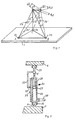
- ball joints (3a, 3b and 3c) are provided on points (A, B, C) on a base plate (1), in which legs (2a, 2b and 2c) are rotatably mounted on all sides.
- the legs (2a, 2b, 2c) converge at a point (D) or in its immediate vicinity. They are articulated in the area of point (D).
- the legs (2a, 2b, 2c) have the lengths L 1 , L 2 and L 3 .
- leg (2a) moves into position (2a')
- leg (2b) into position ( 2b ')
- the leg (2c) in position (2c') The lengths of the legs (2a, 2b, 2c) must change so that this change in position of point (D) to (D ') is possible.
- the length L 1 of the leg (2a) changes by the amount dL 1
- the length of the leg (2b) changes by the amount dL 2
- the length of the leg (2c) changes by the amount dL 3 .
- Such a shift can also be fundamentally be carried out by hand or by other means.
- the legs, as shown for the leg (2a), are designed to be extendable.
- the leg (2a) can be pivoted on all sides by means of a ball joint (25).
- the leg consists of a cylindrical part (26) in which a piston (27) is slidably mounted.
- the piston (27) carries a piston rod (28).
- the piston rod (28) is fastened to the body (4) of FIG. 2 to be described by means of a ball joint (29).
- the body (4), as shown for the point (D) in Fig. 1, can be moved in the three Cartesian coordinate directions.
- the leg (2a) changes its angle to the base plate (1) and also to the body (4) (Fig. 1), but also its length L 1 with reference to the centers of the balls (25 and 29) of the ball joints in the Points (A and D).
- the cylindrical part (26) In order to detect the size of the change in length of the leg (2a) from a normal position, the cylindrical part (26) carries a scale (31). The change in length of the leg (2a) can be read off on the scale (31) by means of a reading index (32) which is connected to the piston rod (28) at point (E) via a rod (33).
- the extension size of the piston rod (28) and thus the change in length dL 1 of the leg (2a) corresponds to the displacement size of the piston (27) and thus the piston rod (28) of the body (4) at the articulation point of the ball joint (29).
- the detection of the change in length dL 1 can be carried out by sensors using modern means and, for example, entered as a value in a measuring and control device (not shown).
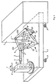
- FIG. 2 shows an embodiment of the coordinate measuring machine, with six legs on the base plate (1) (2a, 2b, 2c, 2d, 2e, 2f) are provided. Two legs each are in the area of the points (A ', B', C ') on the base plate (1) in adjacent ball joints, as in Fig. 3 for the leg (2a) shown, arranged. The camps two each Legs are close together, but this is not mandatory is. From each point area (A ', B', C ') is included Pair of legs (2a, 2b; 2c, 2d; 2e, 2f). One of the legs each pair is to a corner area (A ") of the body (4) led, the other leg (2b) of the couple to the corner area (B ") of the body (4). The legs stored in the area (B ') (2c and 2d) are arranged such that the leg (2c) in Area of the point (B ") is connected to the body (4) and the leg (2d) in the area of the point (C ") with this Body
- a corresponding arrangement is for the pair of legs (2e, 2f) hit by one of the legs, namely the leg (2e), connected to the body (4) in the area of the point (C ") and the other leg (2f) with the body (4) in the Area of point (A ").
- the body (4) forms a rod (35a, 35b and 35c) existing triangular frame.
- the poles (35a, 35b, 35c) are firmly connected. They wear a boom (5) to which the probe (6) is attached.
- By changing the length of the legs (2a to 2f) one can the base plate (1) arranged workpiece (8) in one Measuring point can be touched.
- the base plate (1) therefore consists of a thermal insensitive material and has a strength that Bends and linear expansion of the base plate (1) excluded are.
- measuring devices can also be provided be, which constantly the location of the articulation points of the Legs on the base plate (1) in the area of the points (A ', B' and C ') and check any positional deviations in this way Convert that corrections are made to the measured values can be. The same goes for those in the fields (A ", B", C ") legs articulated on the body (4).
- the base plate (1) can consist of several Parts exist, but then put them back together at the measuring location are (not shown).
- Base plate (1) To avoid unwanted changes in length of the legs (2) to cause by vibrations or the like is Base plate (1) according to FIG. 2 on damping elements (9), for example, hydraulically operating shock absorbers.
- the controller (not shown in Fig. 2) calculates the change in length of the legs to that desired by the operator Coordinates around and thus allows a movement of the Probe along Cartesian coordinate axes during deflection a control lever.
- the connection to the evaluation computer takes place as with conventional coordinate measuring machines.
- legs can also determine the change in Kick the angular position of at least one leg (not shown).
- the workpiece (8) to be measured is open a turntable (40) carried by the base plate (1) arranged around the axis (F-F) in the direction of the arrow (41) is rotatable.
Landscapes
- Physics & Mathematics (AREA)
- General Physics & Mathematics (AREA)
- A Measuring Device Byusing Mechanical Method (AREA)
- Length Measuring Devices With Unspecified Measuring Means (AREA)
Claims (33)
- Machine de mesure de coordonnées comprenant un porte-pièces destiné à recevoir la pièce à mesurer (8), une tête de balayage (6) mobile, qui est destinée à palper la pièce (8) et qui est montée de manière fixe, de manière amovible fixe ou de manière mobile contre un bras (5) d'un corps (4) sensiblement rigide, un mécanisme de positionnement (2) pour la tête de balayage (6), destiné à positionner la tête de balayage (6) par rapport au porte-pièces, ainsi qu'une unité d'alimentation, de commande et d'analyse, sachant que le mécanisme de positionnement (2) est formé par au moins trois jambes (2a, 2b, 2c, 2d, 2e, 2f) montées sur une plaque de base (1) de manière à pouvoir pivoter dans tous les sens contre au moins trois points (A, B, C), prévus de manière fixe, la longueur desdites jambes et/ou leur inclinaison par rapport à la plaque de base (1) étant réglable de manière mesurable et lesdites jambes étant fixées par leurs autres extrémités, de manière à pouvoir pivoter dans tous les sens, contre le corps (4) supportant la tête de balayage (6), caractérisée en ce que le porte-pièces destiné à recevoir la pièce à mesurer (8) est disposé en dehors de l'espace occupé par les jambes (2a, 2b, 2c, 2d, 2e, 2f) sur la plaque de base (1).
- Machine de mesure de coordonnées selon la revendication 1, caractérisée en ce que le mécanisme de positionnement est conçu en même temps comme instrument de mesure.
- Machine de mesure de coordonnées selon la revendication 1, caractérisée en ce que le mécanisme de positionnement comporte au moins six jambes (2a à 2f) réglables en longueur et supportant le corps (4).
- Machine de mesure de coordonnées selon la revendication 3, caractérisée en ce que trois paires de jambes (2a, 2b ; 2c, 2d ; 2e, 2f) sont articulées contre la plaque de base (1), de telle sorte que les points d'articulation de chaque paire de jambes (2a, 2b ; 2c, 2d ; 2e, 2f) sont situés dans des zones voisines (A', B', C') sur la plaque de base et le point de rotation d'une jambe, dans chaque paire de jambes, au voisinage du point de rotation d'une jambe de la paire contiguë, est disposé contre le corps (4) déplaçable, supportant la tête de balayage (6), dans des zones (A'', B'', C'').
- Machine de mesure de coordonnées selon la revendication 1, caractérisée en ce que le corps (4) supporté par les jambes (2a à 2f) est formé par un cadre (35a, 35b, 35c).
- Machine de mesure de coordonnées selon la revendication 5, caractérisée en ce que le cadre (35a, 35b, 35c) est conçu en forme de triangle et les zones (A'', B'', C'') du point de rotation des jambes sont situées dans les angles du cadre.
- Machine de mesure de coordonnées selon la revendication 6, caractérisée en ce que le bras (5) est prévu dans un angle du cadre (35a, 35b, 35c).
- Machine de mesure de coordonnées selon la revendication 7, caractérisée en ce que le bras (5) est orienté en s'écartant du cadre (35a, 35b, 35c).
- Machine de mesure de coordonnées selon la revendication 1, caractérisée en ce que la plaque de base (1) est identique au porte-pièces.
- Machine de mesure de coordonnées selon la revendication 9, caractérisée en ce que la plaque de base (1) est formée par plusieurs parties.
- Machine de mesure de coordonnées selon la revendication 1, caractérisée en ce que la plaque de base (1) est disposée sur des amortisseurs (9).
- Machine de mesure de coordonnées selon la revendication 1, caractérisée en ce que la plaque de base (1) est rigide en elle-même et insensible aux influences thermiques.
- Machine de mesure de coordonnées selon la revendication 1, caractérisée en ce que ladite machine de mesure de coordonnées comporte des capteurs, qui enregistrent la position des points d'articulation (A', B', C') des jambes sur la plaque de base (1) et signalent des variations de position de ces points d'articulation à l'unité de mesure et de commande.
- Machine de mesure de coordonnées selon la revendication 1, caractérisée en ce que les moyens d'articulation des jambes (2a à 2f) sur la plaque de base (1) et contre le corps (4) sont formés par des joints à rotule à faible frottement et sans jeu.
- Machine de mesure de coordonnées selon la revendication 14, caractérisée en ce que les joints à rotule sont conçus sous forme de coussinets d'air, de coussinets hydrauliques, de paliers lisses ou de paliers à roulement à billes ou des éléments analogues.
- Machine de mesure de coordonnées selon la revendication 1, caractérisée en ce que les moyens d'articulation des jambes (2a à 2f) sont formés par des éléments de flexion.
- Machine de mesure de coordonnées selon la revendication 1, caractérisée en ce que les moyens d'articulation sont formés non seulement par des coussinets d'air, des coussinets hydrauliques, des paliers lisses ou des paliers à roulement à billes ou des éléments analogues, mais aussi par des éléments de flexion.
- Machine de mesure de coordonnées selon la revendication 1, caractérisée en ce que la plaque de base (1), les jambes (2a à 2f) et le corps (4) supportant la tête de balayage (6) sont disposés dans un boítier (7), à travers lequel le bras (5) portant la tête de mesure (6) s'engage vers l'extérieur.
- Machine de mesure de coordonnées selon la revendication 1, caractérisée en ce que les jambes (2a à 2f) sont conçues selon un mode de construction identique.
- Machine de mesure de coordonnées selon la revendication 1, caractérisée en ce que la longueur des jambes (2a à 2f) est réglable par voie hydraulique, pneumatique ou électromotrice au moyen d'une broche, d'un moteur linéaire ou d'un élément analogue.
- Machine de mesure de coordonnées selon la revendication 1, caractérisée en ce que chaque jambe réglable en longueur porte un système à échelle graduée (31, 32), qui permet de lire ou de palper la longueur de la jambe par rapport aux points d'articulation sur la plaque de base (1) et contre le corps (4).
- Machine de mesure de coordonnées selon la revendication 1, caractérisée en ce que les jambes (2a à 2f) portent les capteurs enregistrant la longueur extraite.
- Machine de mesure de coordonnées selon la revendication 1, caractérisée en ce que sur les points d'articulation des jambes (2a à 2f) contre la plaque de base (1) et/ou contre le corps (4) sont prévus des systèmes de mesure angulaire, qui enregistrent l'angle d'inclinaison des jambes (2a à 2f) par rapport à la plaque de base (1) ou au corps (4).
- Machine de mesure de coordonnées selon la revendication 1, caractérisée en ce que les jambes (2a à 2f) portent des capteurs de charge et/ou des capteurs de température.
- Machine de mesure de coordonnées selon la revendication 1, caractérisée en ce qu'il est prévu un système de mesure supplémentaire, indépendant des jambes, pour mesurer la position du corps (4) supportant la tête de balayage (6) ou de la tête de balayage (6) elle-même.
- Machine de mesure de coordonnées selon la revendication 1, caractérisée en ce qu'au moins une jambe, dans sa position de départ, a une longueur différente de celle des autres jambes.
- Machine de mesure de coordonnées selon la revendication 1, caractérisée en ce qu'au moins l'une des jambes (2a à 2f) a une longueur et/ou une position prédéfinies invariables.
- Machine de mesure de coordonnées selon la revendication 1, caractérisée en ce que les points d'articulation des joints à rotule sont conçus de manière à pouvoir être décalés sur la plaque de base (1).
- Machine de mesure de coordonnées selon la revendication 1, caractérisée en ce que la plaque de base (1) est formée par plusieurs pièces assemblées entre elles de manière rigide en formant un angle donné les unes par rapport aux autres, et en ce que chacune des pièces porte au moins une des jambes (2a à 2f).
- Machine de mesure de coordonnées selon la revendication 1, caractérisée en ce que les jambes (2a à 2f) sont agencées par paires, de telle sorte que leurs orientations forment pratiquement un système orthogonal dans une partie définie du volume de mesure.
- Machine de mesure de coordonnées selon la revendication 1, caractérisée en ce que, pour augmenter la précision de mesure, une correction exécutée par calcul dans l'unité de commande peut être superposée à la mesure de la longueur des jambes (2a à 2f) et, le cas échéant, à d'autres écarts géométriques des valeurs de mesure, et en ce que le calcul de la valeur de chaque correction des écarts est effectué sur chaque élément, tel que les jambes (2a à 2f) et/ou le bras (5) pendant le processus de mesure sur une pièce spécifique.
- Machine de mesure de coordonnées selon la revendication 1, caractérisée en ce que le porte-pièces destiné à recevoir la pièce à mesurer est conçu sous forme de table rotative (40).
- Machine de mesure de coordonnées selon la revendication 32, caractérisée en ce que la table rotative (40) ne possède qu'un nombre limité de positions de rotation possibles, le plus petit pas angulaire possible étant de l'ordre de grandeur du domaine de pivotement possible du corps (4), supportant la tête de balayage (6), autour de l'axe (F) de la table rotative.
Applications Claiming Priority (2)
| Application Number | Priority Date | Filing Date | Title |
|---|---|---|---|
| DE19534535 | 1995-09-18 | ||
| DE19534535A DE19534535C2 (de) | 1995-09-18 | 1995-09-18 | Koordinatenmeßmaschine |
Publications (3)
| Publication Number | Publication Date |
|---|---|
| EP0763708A2 EP0763708A2 (fr) | 1997-03-19 |
| EP0763708A3 EP0763708A3 (fr) | 1998-10-14 |
| EP0763708B1 true EP0763708B1 (fr) | 2002-10-02 |
Family
ID=7772456
Family Applications (1)
| Application Number | Title | Priority Date | Filing Date |
|---|---|---|---|
| EP96113300A Expired - Lifetime EP0763708B1 (fr) | 1995-09-18 | 1996-08-20 | Machine de mesure de coordonnées |
Country Status (3)
| Country | Link |
|---|---|
| US (1) | US5909939A (fr) |
| EP (1) | EP0763708B1 (fr) |
| DE (2) | DE19534535C2 (fr) |
Cited By (1)
| Publication number | Priority date | Publication date | Assignee | Title |
|---|---|---|---|---|
| CN101253383B (zh) * | 2005-07-26 | 2011-02-02 | 美凯克斯有限公司 | 坐标测量机 |
Families Citing this family (64)
| Publication number | Priority date | Publication date | Assignee | Title |
|---|---|---|---|---|
| DE19703738C2 (de) * | 1997-02-01 | 2001-11-08 | Leitz Brown & Sharpe Mestechni | Verfahren zur Bestimmung geometriebestimmender Parameter eines Koordinatenmeßgerätes |
| DE19720049B4 (de) * | 1997-05-14 | 2006-01-19 | Hexagon Metrology Gmbh | Verfahren zur Steuerung eines motorischen Koordinatenmeßgerätes sowie Koordinatenmeßgerät zur Durchführung des Verfahrens |
| DE19840334A1 (de) * | 1998-02-02 | 1999-08-05 | Daimler Chrysler Ag | Vorrichtung zur Verwendung als Navigationskulisse bei der Vermessung von Objekten |
| US6021579A (en) * | 1998-04-01 | 2000-02-08 | Joseph M. Schimmels | Spatial parallel compliant mechanism |
| US6587802B1 (en) * | 1998-09-17 | 2003-07-01 | Dr. Johannes Heidenhain Gmbh | Calibration device for a parallel kinematic manipulator |
| DE19913912B4 (de) * | 1999-03-26 | 2006-04-06 | Wissner, Rolf, Dipl.-Ing. | Meß- und/oder Positioniervorrichtung |
| US6298572B1 (en) | 2000-01-10 | 2001-10-09 | Mcauley Brian | Universal holding device for effectuating three dimensional measurement of a part and method of constructing such a holding device |
| WO2001085402A2 (fr) | 2000-05-12 | 2001-11-15 | Alberta Research Council Inc. | Plate-forme mobile et procede d'utilisation |
| US6668466B1 (en) | 2000-10-19 | 2003-12-30 | Sandia Corporation | Highly accurate articulated coordinate measuring machine |
| DE10126848B4 (de) * | 2001-06-01 | 2006-02-02 | Siemens Ag | Produktionsmaschine |
| EP1271092A1 (fr) * | 2001-06-28 | 2003-01-02 | Haim Abitan | Système et méthode de conception et d'analyse d'un montage optique |
| US6741912B2 (en) * | 2001-07-02 | 2004-05-25 | Microbotic A/S | Flexible tool for handling small objects |
| US7241070B2 (en) * | 2001-07-13 | 2007-07-10 | Renishaw Plc | Pivot joint |
| US7040033B2 (en) * | 2001-10-05 | 2006-05-09 | Trustees Of Stevens Institute Of Technology | Six degrees of freedom precision measuring system |
| DE10151563A1 (de) | 2001-10-23 | 2003-04-30 | Heidenhain Gmbh Dr Johannes | Positionsmessgerät |
| USRE42082E1 (en) | 2002-02-14 | 2011-02-01 | Faro Technologies, Inc. | Method and apparatus for improving measurement accuracy of a portable coordinate measurement machine |
| US7073271B2 (en) * | 2002-02-14 | 2006-07-11 | Faro Technologies Inc. | Portable coordinate measurement machine |
| US7246030B2 (en) * | 2002-02-14 | 2007-07-17 | Faro Technologies, Inc. | Portable coordinate measurement machine with integrated line laser scanner |
| US7881896B2 (en) | 2002-02-14 | 2011-02-01 | Faro Technologies, Inc. | Portable coordinate measurement machine with integrated line laser scanner |
| US6957496B2 (en) * | 2002-02-14 | 2005-10-25 | Faro Technologies, Inc. | Method for improving measurement accuracy of a portable coordinate measurement machine |
| US7519493B2 (en) * | 2002-02-14 | 2009-04-14 | Faro Technologies, Inc. | Portable coordinate measurement machine with integrated line laser scanner |
| US6973734B2 (en) * | 2002-02-14 | 2005-12-13 | Faro Technologies, Inc. | Method for providing sensory feedback to the operator of a portable measurement machine |
| ATE365903T1 (de) * | 2002-02-14 | 2007-07-15 | Faro Tech Inc | Ein gelenkarm für eine tragbare koordinatenmessmaschine |
| US6952882B2 (en) * | 2002-02-14 | 2005-10-11 | Faro Technologies, Inc. | Portable coordinate measurement machine |
| US6662651B1 (en) * | 2002-08-15 | 2003-12-16 | Javelin Sports, Inc. | Portable exercise device |
| EP1725916B1 (fr) * | 2004-02-04 | 2012-11-21 | Mazor Robotics Ltd. | Systeme de verification pour pose de robot |
| SE527248C2 (sv) * | 2004-06-28 | 2006-01-31 | Hexagon Metrology Ab | Mätprob för användning i koordinatmätmaskiner |
| US7275332B2 (en) * | 2005-02-22 | 2007-10-02 | Carestream Health, Inc. | Multi-axis positioning apparatus |
| US20070284502A1 (en) * | 2006-06-13 | 2007-12-13 | Nikon Corporation | Hexapod kinematic mountings for optical elements, and optical systems comprising same |
| GB0611979D0 (en) * | 2006-06-16 | 2006-07-26 | Renishaw Plc | Coordinate positioning machine |
| ATE467097T1 (de) * | 2006-06-16 | 2010-05-15 | Renishaw Plc | Verlängerbare beinbaugruppe für eine positionsmessvorrichtung |
| CA2669878C (fr) * | 2006-11-20 | 2017-01-03 | Hexagon Metrology Ab | Machine de mesure de coordonnees avec joint ameliore |
| US9551575B2 (en) | 2009-03-25 | 2017-01-24 | Faro Technologies, Inc. | Laser scanner having a multi-color light source and real-time color receiver |
| DE102009015920B4 (de) | 2009-03-25 | 2014-11-20 | Faro Technologies, Inc. | Vorrichtung zum optischen Abtasten und Vermessen einer Umgebung |
| DE102009057101A1 (de) | 2009-11-20 | 2011-05-26 | Faro Technologies, Inc., Lake Mary | Vorrichtung zum optischen Abtasten und Vermessen einer Umgebung |
| US9529083B2 (en) | 2009-11-20 | 2016-12-27 | Faro Technologies, Inc. | Three-dimensional scanner with enhanced spectroscopic energy detector |
| US9113023B2 (en) | 2009-11-20 | 2015-08-18 | Faro Technologies, Inc. | Three-dimensional scanner with spectroscopic energy detector |
| US9210288B2 (en) | 2009-11-20 | 2015-12-08 | Faro Technologies, Inc. | Three-dimensional scanner with dichroic beam splitters to capture a variety of signals |
| US9163922B2 (en) | 2010-01-20 | 2015-10-20 | Faro Technologies, Inc. | Coordinate measurement machine with distance meter and camera to determine dimensions within camera images |
| US9879976B2 (en) | 2010-01-20 | 2018-01-30 | Faro Technologies, Inc. | Articulated arm coordinate measurement machine that uses a 2D camera to determine 3D coordinates of smoothly continuous edge features |
| US9607239B2 (en) | 2010-01-20 | 2017-03-28 | Faro Technologies, Inc. | Articulated arm coordinate measurement machine having a 2D camera and method of obtaining 3D representations |
| US9628775B2 (en) | 2010-01-20 | 2017-04-18 | Faro Technologies, Inc. | Articulated arm coordinate measurement machine having a 2D camera and method of obtaining 3D representations |
| JP2013517503A (ja) | 2010-01-20 | 2013-05-16 | ファロ テクノロジーズ インコーポレーテッド | 可搬型の関節アーム座標測定機の移動を改善するための傾斜計の使用 |
| DE102010020925B4 (de) | 2010-05-10 | 2014-02-27 | Faro Technologies, Inc. | Verfahren zum optischen Abtasten und Vermessen einer Umgebung |
| US9168654B2 (en) | 2010-11-16 | 2015-10-27 | Faro Technologies, Inc. | Coordinate measuring machines with dual layer arm |
| CN107255462B (zh) * | 2011-07-08 | 2019-07-23 | 卡尔蔡司工业测量技术有限公司 | 在测量工件的坐标时的误差修正和/或避免 |
| DE102012100609A1 (de) | 2012-01-25 | 2013-07-25 | Faro Technologies, Inc. | Vorrichtung zum optischen Abtasten und Vermessen einer Umgebung |
| US8997362B2 (en) | 2012-07-17 | 2015-04-07 | Faro Technologies, Inc. | Portable articulated arm coordinate measuring machine with optical communications bus |
| US10067231B2 (en) | 2012-10-05 | 2018-09-04 | Faro Technologies, Inc. | Registration calculation of three-dimensional scanner data performed between scans based on measurements by two-dimensional scanner |
| US9513107B2 (en) | 2012-10-05 | 2016-12-06 | Faro Technologies, Inc. | Registration calculation between three-dimensional (3D) scans based on two-dimensional (2D) scan data from a 3D scanner |
| DE102012109481A1 (de) | 2012-10-05 | 2014-04-10 | Faro Technologies, Inc. | Vorrichtung zum optischen Abtasten und Vermessen einer Umgebung |
| CN103292709B (zh) * | 2013-05-24 | 2015-09-09 | 深圳市华星光电技术有限公司 | 测长机日常检测与自动补正方法 |
| WO2017073055A1 (fr) * | 2015-10-27 | 2017-05-04 | パナソニックIpマネジメント株式会社 | Dispositif de transport |
| TWI585363B (zh) | 2015-12-01 | 2017-06-01 | 國立清華大學 | 應用於量測之雙球桿系統及其誤差補償方法 |
| DE102015122844A1 (de) | 2015-12-27 | 2017-06-29 | Faro Technologies, Inc. | 3D-Messvorrichtung mit Batteriepack |
| EP3896384A1 (fr) * | 2016-04-08 | 2021-10-20 | Renishaw PLC | Machine de positionnement par coordonnées |
| US10962166B1 (en) * | 2017-08-10 | 2021-03-30 | United States Of America As Represented By The Administrator Of The National Aeronautics And Space Administration | Hexapod pose knowledge improvement by joint location calibration with individual strut length differential measurements |
| EP3450905B1 (fr) * | 2017-09-01 | 2020-04-22 | Hexagon Technology Center GmbH | Machine de mesure de coordonnées par hexapode ou similaire à un hexapode non cartésien |
| GB2568459B (en) | 2017-10-13 | 2020-03-18 | Renishaw Plc | Coordinate positioning machine |
| GB201820935D0 (en) * | 2018-12-21 | 2019-02-06 | Renishaw Plc | Manufacturing system and method |
| DE102019205042B4 (de) | 2019-04-09 | 2023-05-17 | Carl Zeiss Industrielle Messtechnik Gmbh | Vorrichtung und Verfahren zur Positionierung eines Sensors oder Sensorteils |
| GB2582972B (en) * | 2019-04-12 | 2021-07-14 | Renishaw Plc | Coordinate positioning machine |
| CN113865534B (zh) * | 2021-09-01 | 2023-03-21 | 慈溪莱普森机械有限公司 | 三坐标测量仪 |
| CN115014171B (zh) * | 2022-08-04 | 2022-10-21 | 常州皓之鼎高分子材料有限公司 | 一种新能源汽车用eva泡棉吸音片尺寸测量方法及装置 |
Citations (2)
| Publication number | Priority date | Publication date | Assignee | Title |
|---|---|---|---|---|
| WO1991003145A1 (fr) * | 1989-09-01 | 1991-03-21 | Kearney & Trecker Corporation | Machine-outil a six axes |
| WO1995014905A1 (fr) * | 1993-11-25 | 1995-06-01 | Renishaw Plc | Dispositifs servant a mesurer des positions |
Family Cites Families (17)
| Publication number | Priority date | Publication date | Assignee | Title |
|---|---|---|---|---|
| DD141061A1 (de) * | 1978-12-29 | 1980-04-09 | Werner Krieg | Einrichtung zum bestimmen der lage und abmessungen von gegenstaenden |
| SU1040318A1 (ru) * | 1981-02-25 | 1983-09-07 | Институт Машиноведения Им.А.А.Благонравова | Устройство дл измерени пространственного перемещени тел |
| US4536690A (en) * | 1982-10-19 | 1985-08-20 | Calspan Corporation | Tool-supporting self-propelled robot platform |
| FR2547916A1 (fr) * | 1983-06-27 | 1984-12-28 | Lemoine Patrick Neuhaus | Procede de mesure de deplacement d'un palpeur dans l'espace |
| DE3504464C1 (de) * | 1985-02-09 | 1986-04-17 | Fraunhofer-Gesellschaft zur Förderung der angewandten Forschung e.V., 8000 München | Transportables Meßgerät zur Überprüfung der Positioniergenauigkeit eines programmgesteuerten Gerätearmes |
| GB2180117B (en) * | 1985-09-05 | 1989-09-06 | Ferranti Plc | Three-dimensional position measuring apparatus |
| DE3637410A1 (de) * | 1986-11-03 | 1988-05-11 | Zeiss Carl Fa | Verfahren zur messung von drehtischabweichungen |
| DE3717459A1 (de) * | 1987-05-23 | 1988-12-01 | Zeiss Carl Fa | Handgefuehrtes koordinatenmessgeraet |
| SU1548652A1 (ru) * | 1988-01-11 | 1990-03-07 | Предприятие П/Я А-7880 | Устройство дл измерени геометрических размеров тела и его положени в пространстве |
| SU1583726A1 (ru) * | 1988-04-12 | 1990-08-07 | Институт Машиноведения Им.А.А.Благонравова | L-координатный пространственный механизм |
| US5050112A (en) * | 1989-08-08 | 1991-09-17 | The United States Of America As Represented By The United States Department Of Energy | Specimen coordinate automated measuring machine/fiducial automated measuring machine |
| US5179786A (en) * | 1991-04-22 | 1993-01-19 | Shelton Russell S | Measuring apparatus with temperature control |
| DE4218984A1 (de) * | 1992-06-10 | 1993-12-16 | Zeiss Carl Jena Gmbh | Positioniersystem für optische Prüfgeräte |
| US5412880A (en) * | 1993-02-23 | 1995-05-09 | Faro Technologies Inc. | Method of constructing a 3-dimensional map of a measurable quantity using three dimensional coordinate measuring apparatus |
| US5402582A (en) * | 1993-02-23 | 1995-04-04 | Faro Technologies Inc. | Three dimensional coordinate measuring apparatus |
| US5428446A (en) * | 1993-03-29 | 1995-06-27 | Ziegert; John C. | Measurement instrument with interferometer and method |
| GB9401692D0 (en) * | 1994-01-28 | 1994-03-23 | Renishaw Plc | Performing measurement or calibration on positioning machines |
-
1995
- 1995-09-18 DE DE19534535A patent/DE19534535C2/de not_active Revoked
-
1996
- 1996-08-20 DE DE59609743T patent/DE59609743D1/de not_active Expired - Lifetime
- 1996-08-20 EP EP96113300A patent/EP0763708B1/fr not_active Expired - Lifetime
- 1996-09-16 US US08/714,372 patent/US5909939A/en not_active Expired - Lifetime
Patent Citations (2)
| Publication number | Priority date | Publication date | Assignee | Title |
|---|---|---|---|---|
| WO1991003145A1 (fr) * | 1989-09-01 | 1991-03-21 | Kearney & Trecker Corporation | Machine-outil a six axes |
| WO1995014905A1 (fr) * | 1993-11-25 | 1995-06-01 | Renishaw Plc | Dispositifs servant a mesurer des positions |
Cited By (1)
| Publication number | Priority date | Publication date | Assignee | Title |
|---|---|---|---|---|
| CN101253383B (zh) * | 2005-07-26 | 2011-02-02 | 美凯克斯有限公司 | 坐标测量机 |
Also Published As
| Publication number | Publication date |
|---|---|
| US5909939A (en) | 1999-06-08 |
| DE59609743D1 (de) | 2002-11-07 |
| DE19534535A1 (de) | 1997-03-20 |
| DE19534535C2 (de) | 2000-05-31 |
| EP0763708A3 (fr) | 1998-10-14 |
| EP0763708A2 (fr) | 1997-03-19 |
Similar Documents
| Publication | Publication Date | Title |
|---|---|---|
| EP0763708B1 (fr) | Machine de mesure de coordonnées | |
| EP0456276B1 (fr) | Appareil pour mesurer les coordonnées | |
| EP0597299B1 (fr) | Dispositif de mesure de coordonnées | |
| DE3740070A1 (de) | Dreh-schwenk-einrichtung fuer tastkoepfe von koordinatenmessgeraeten | |
| DE69532091T2 (de) | Verfahren und Vorrichtung zur Durchführung von Messungen | |
| EP1462760B1 (fr) | Dispositif de mesure de la position d'un capteur dans une machine de mesure de coordonnées | |
| DE102007022326B4 (de) | Koordinatenmessgerät zum Bestimmen von Raumkoordinaten an einem Messobjekt sowie Dreh-Schwenk-Mechanismus für ein solches Koordinatenmessgerät | |
| DE3690033C2 (de) | Koordinaten-Messinstrument | |
| EP0443422B1 (fr) | Dispositif de mesure de coordonnées | |
| EP0426095B1 (fr) | Machine de mesure de coordonnées | |
| EP1393012B1 (fr) | Procede de determination de proprietes d'un appareil de mesure de coordonnees et objet de test correspondant | |
| DE3735075A1 (de) | Pruefeinrichtung und verfahren zur bestimmung der messunsicherheit von koordinatenmessgeraeten | |
| EP0951967B1 (fr) | Dispositif pour déterminer la précision de la position sur une voie des éléments mobiles de machine | |
| DD294337A5 (de) | Messeinrichtung | |
| EP1415130B1 (fr) | Dispositif pour detecter la position relative de deux corps depla ables l'un par rapport a l'autre | |
| DE4345095C1 (de) | Vorrichtung zur exakten Bestimmung von Raumpunkten bei einer mehrere Bahnachsen aufweisenden Maschine, insbesondere Meßmaschine | |
| EP3308100B1 (fr) | Appareil de mesure de coordonnées comprenant une traverse mobile et procédé servant à la fabrication d'un appareil de mesure de coordonnées de ce type | |
| DE4447904B4 (de) | Koordinatenmessmaschine zum Messen von dreidimensionalen Koordinaten | |
| DE102011054932B4 (de) | Koordinatenmessgerät | |
| DE102010049662B4 (de) | Vorrichtung zur Bestimmung von Roll-, Nick - und Gierwinkeln | |
| DE10328640B4 (de) | Messanordnung zur Prüfung der Arbeitsgenauigkeit einer Maschine | |
| DE3733617A1 (de) | Mehrkoordinaten-messmaschine | |
| DE19640674C2 (de) | Verfahren zur Ermittlung und Korrektur der maschinenbedingten Meßfehler eines Koordinatenmeßgerätes von nicht kartesischem und/oder nichtstarrem Aufbau | |
| DE1206600B (de) | Vorrichtung zum Messen von Innenkegeln in Werkstuecken | |
| DE3740069A1 (fr) |
Legal Events
| Date | Code | Title | Description |
|---|---|---|---|
| PUAI | Public reference made under article 153(3) epc to a published international application that has entered the european phase |
Free format text: ORIGINAL CODE: 0009012 |
|
| AK | Designated contracting states |
Kind code of ref document: A2 Designated state(s): CH DE FR GB IT LI |
|
| PUAL | Search report despatched |
Free format text: ORIGINAL CODE: 0009013 |
|
| AK | Designated contracting states |
Kind code of ref document: A3 Designated state(s): CH DE FR GB IT LI |
|
| 17P | Request for examination filed |
Effective date: 19981028 |
|
| 17Q | First examination report despatched |
Effective date: 20010613 |
|
| GRAG | Despatch of communication of intention to grant |
Free format text: ORIGINAL CODE: EPIDOS AGRA |
|
| GRAG | Despatch of communication of intention to grant |
Free format text: ORIGINAL CODE: EPIDOS AGRA |
|
| GRAH | Despatch of communication of intention to grant a patent |
Free format text: ORIGINAL CODE: EPIDOS IGRA |
|
| GRAH | Despatch of communication of intention to grant a patent |
Free format text: ORIGINAL CODE: EPIDOS IGRA |
|
| RAP1 | Party data changed (applicant data changed or rights of an application transferred) |
Owner name: BROWN & SHARPE GMBH |
|
| GRAA | (expected) grant |
Free format text: ORIGINAL CODE: 0009210 |
|
| AK | Designated contracting states |
Kind code of ref document: B1 Designated state(s): CH DE FR GB IT LI |
|
| PG25 | Lapsed in a contracting state [announced via postgrant information from national office to epo] |
Ref country code: IT Free format text: LAPSE BECAUSE OF FAILURE TO SUBMIT A TRANSLATION OF THE DESCRIPTION OR TO PAY THE FEE WITHIN THE PRESCRIBED TIME-LIMIT;WARNING: LAPSES OF ITALIAN PATENTS WITH EFFECTIVE DATE BEFORE 2007 MAY HAVE OCCURRED AT ANY TIME BEFORE 2007. THE CORRECT EFFECTIVE DATE MAY BE DIFFERENT FROM THE ONE RECORDED. Effective date: 20021002 Ref country code: FR Free format text: LAPSE BECAUSE OF FAILURE TO SUBMIT A TRANSLATION OF THE DESCRIPTION OR TO PAY THE FEE WITHIN THE PRESCRIBED TIME-LIMIT Effective date: 20021002 |
|
| REG | Reference to a national code |
Ref country code: GB Ref legal event code: FG4D Free format text: NOT ENGLISH |
|
| REG | Reference to a national code |
Ref country code: CH Ref legal event code: EP |
|
| GBT | Gb: translation of ep patent filed (gb section 77(6)(a)/1977) |
Effective date: 20021002 |
|
| REF | Corresponds to: |
Ref document number: 59609743 Country of ref document: DE Date of ref document: 20021107 |
|
| EN | Fr: translation not filed | ||
| PLBE | No opposition filed within time limit |
Free format text: ORIGINAL CODE: 0009261 |
|
| STAA | Information on the status of an ep patent application or granted ep patent |
Free format text: STATUS: NO OPPOSITION FILED WITHIN TIME LIMIT |
|
| PG25 | Lapsed in a contracting state [announced via postgrant information from national office to epo] |
Ref country code: LI Free format text: LAPSE BECAUSE OF NON-PAYMENT OF DUE FEES Effective date: 20030831 Ref country code: CH Free format text: LAPSE BECAUSE OF NON-PAYMENT OF DUE FEES Effective date: 20030831 |
|
| 26N | No opposition filed |
Effective date: 20030703 |
|
| REG | Reference to a national code |
Ref country code: CH Ref legal event code: PL |
|
| PGFP | Annual fee paid to national office [announced via postgrant information from national office to epo] |
Ref country code: GB Payment date: 20150819 Year of fee payment: 20 Ref country code: DE Payment date: 20150821 Year of fee payment: 20 |
|
| REG | Reference to a national code |
Ref country code: DE Ref legal event code: R071 Ref document number: 59609743 Country of ref document: DE |
|
| REG | Reference to a national code |
Ref country code: GB Ref legal event code: PE20 Expiry date: 20160819 |
|
| PG25 | Lapsed in a contracting state [announced via postgrant information from national office to epo] |
Ref country code: GB Free format text: LAPSE BECAUSE OF EXPIRATION OF PROTECTION Effective date: 20160819 |