EP0763708B1 - Coordinate measuring machine - Google Patents
Coordinate measuring machine Download PDFInfo
- Publication number
- EP0763708B1 EP0763708B1 EP96113300A EP96113300A EP0763708B1 EP 0763708 B1 EP0763708 B1 EP 0763708B1 EP 96113300 A EP96113300 A EP 96113300A EP 96113300 A EP96113300 A EP 96113300A EP 0763708 B1 EP0763708 B1 EP 0763708B1
- Authority
- EP
- European Patent Office
- Prior art keywords
- coordinate measuring
- measuring machine
- machine according
- legs
- base plate
- Prior art date
- Legal status (The legal status is an assumption and is not a legal conclusion. Google has not performed a legal analysis and makes no representation as to the accuracy of the status listed.)
- Expired - Lifetime
Links
Images

Classifications
-
- G—PHYSICS
- G01—MEASURING; TESTING
- G01B—MEASURING LENGTH, THICKNESS OR SIMILAR LINEAR DIMENSIONS; MEASURING ANGLES; MEASURING AREAS; MEASURING IRREGULARITIES OF SURFACES OR CONTOURS
- G01B5/00—Measuring arrangements characterised by the use of mechanical techniques
- G01B5/004—Measuring arrangements characterised by the use of mechanical techniques for measuring coordinates of points
- G01B5/008—Measuring arrangements characterised by the use of mechanical techniques for measuring coordinates of points using coordinate measuring machines
Definitions
- the invention relates to a coordinate measuring machine.
- a tripod the touch probe, one preferably separately arranged supply and control unit and an evaluation computer.
- the tripod has the task, the touch probe move measurably relative to the workpiece.
- This task will according to the prior art by three perpendicular to each other Linear axes solved, of which either two for coordinate measuring machines with a moving measuring table or three in coordinate measuring machines with a fixed measuring table and constructively build on each other.
- the workpiece can also, as in the DE-OS 44 03 901 A1 has been described with one device probe that is derived from an articulated arm robot.
- Each linear axis requires a coordinate measuring machine careful parallel adjustment of the guide and drive and scale as well as auxiliary constructions, such as one Protection of the guide surfaces against dirt, also low-friction Hose and cable guides.
- the articulated arm measuring machines according to DE-OS 44 03 901 A1 have no linear axes and thus avoid part of the the aforementioned principle-related effort. However, build too With this design, all axes on each other, which is too relative leads to large masses to be moved, especially if a complex probe is to be used. thermal or bending of the arms caused by load changes the accuracy of the measurement. The resolution Available encoder is for accuracy in the ⁇ m range unsatisfactory. Coordinate measuring machines in Articulated arm design are in terms of their performance therefore still far from the coordinate measuring machines described conventional design removed.
- Coordinate measuring machines must be checked regularly to ensure compliance with the specified accuracy demonstrated.
- Calibrated test specimens can be used for this such as gauge blocks or spherical plates. It is but also possible through an independent measuring system Check the position of the probe.
- a corresponding control procedure is carried out according to the DE 35 04 464 C1 for determining the positioning accuracy made a tool holder in which the Tool is moved by a robot.
- This Control device is designed as a portable device.
- WO-A-91/03145 is one Machine tool known with six axes, the lower one Has platform and an upper platform. On the lower one Platform is in the space delimited by the legs arranged the workpiece. The upper platform enters Tool, for example a cutting tool or a probe.
- the two platforms are with six movable and Legs adjustable in length joined together.
- This machine tool belonging to the state of the art has the disadvantage that the workpiece in the of the legs limited space is arranged. This can only Workpieces with limited spatial expansion in this machined machine tool belonging to the prior art become. The workpieces cannot be larger than that of the legs and the two platforms be limited space.
- WO-A-91/14905 describes a position measuring device, which like the machine tool above (WO-A-91/03145) has six axes, a lower one Connect the platform to an upper platform.
- the workpiece to be measured is arranged between the legs of the position measuring device and measure with a button.
- this state of the art is the workpiece not arranged between the legs, but still in front of a frame and support structure of the position measuring device (Fig. 11).
- the arrangement of the workpiece within the space formed by the legs and / or within the support and frame construction of the coordinate measuring machine has the disadvantage already mentioned that the Space for receiving the workpiece is a limited spatial Has expansion, so that workpieces only up to to a maximum size in this state of the art belonging position measuring device can be measured. It is also a free and unobstructed manual or automatic loading of the coordinate measuring machine not possible according to this state of the art.
- the technical problem underlying the invention consists in specifying a coordinate measuring machine which easy and inexpensive to manufacture from its basic structure is, however, the desired measurement accuracy guaranteed and speed and in particular also difficult to reach measuring points.
- the probe is carried by a body is that as a relatively light weight frame can be formed, and advantageously at least a point of the body by means of length and / or the angles of adjustable legs in predetermined fixed points articulated to the base plate carrying the workpiece it is possible to use the probe worn by the body in the measuring range of the coordinate measuring machine, for example just by changing the length of the legs to everyone any place to drive. From the measured length of the legs a calculator can easily determine the position of the probe tip Determine the probe and in Cartesian coordinates specify.
- a rigid body in space has six degrees of freedom, namely three translational and three rotatory Degrees of freedom. In order to clearly define the position of the probe, therefore six restrictive conditions are necessary.
- the legs do not need the same in the initial state Show length. It is advantageous to have your legs in train the same type to manufacture them in series production to be able to.
- Six legs can be combined in a known manner Arrange the hexapod type.
- the hexapod design in a machine tool provided.
- the hexapod design should allow to exercise great powers.
- the Probe only one of the legs becomes relative lightweight frame worn, which in turn the Probe carries.
- Typical workpieces of coordinate measuring machines are often roughly cuboid, with several of its six sides special structures, such as holes, are embedded, to determine their geometric characteristics from the measuring machine are. It is always the aim, if possible short buttons work because of long stylus combinations are unwieldy due to the weight of many probes can not be used and loss of accuracy and travel speed limitations to lead.
- Construction is the attachment for the reasons mentioned of the probe head directly on the frame supported by the legs not wanted. It is therefore the probe on End of a boom rigidly connected to the frame appropriate.
- no management function and can therefore with one for the rigidity and for the Use of short buttons optimized, possibly yourself tapered cross section.
- the boom does not carry a scale in the design according to the invention or other sensitive parts that are protected from contamination Need to become.
- the boom should be against thermal Be insensitive to interference.
- Another advantage of the training according to the invention is that the base plates, the legs and the the probe load-bearing body can be arranged in a housing from which the the arm supporting the measuring head protrudes. This will the greatest possible shielding of the movement and registration elements (legs) and their bearings against pollution and external thermal influences reached.
- Another advantage of the training according to the invention is that the holder for the workpiece to be measured arranged outside the space occupied by the legs can be so that an unimpeded manual or automatic loading of the coordinate measuring machine possible is.
- the operator can then, as is the case with Creating a new measuring run is necessary from short Observe the touch point from a distance; would be the probe like from the magazine "Schweizer Maschinenphan", No. 17/1995, pages 26 to 29 known for the tool head, within the space enclosed by the legs arranged, this would be for accessibility and security reasons locked out.
- the one placed on machine tools Demand for the absorption of large forces, whereby a cantilever would be a disadvantage with coordinate measuring machines not because the forces exerted on probing small and also measurable and therefore correctable are.
- the training according to the invention also allows the Recording for the workpiece to be measured on simple Way, for example by loosening a screw connection, to separate from the base plate and make it interchangeable.
- This allows a stationary coordinate measuring machine can be equipped with various workpiece holders or a coordinate measuring machine designed for frequent changes of location, for example, fixed workpiece holders connected become.
- the table for holding the workpiece can also be designed as a turntable, or such Rotary table may be provided on the base plate.
- the turntable can be continuously adjusted vertically on the Base plate standing axis can be rotated or in Intervals.
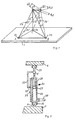
- ball joints (3a, 3b and 3c) are provided on points (A, B, C) on a base plate (1), in which legs (2a, 2b and 2c) are rotatably mounted on all sides.
- the legs (2a, 2b, 2c) converge at a point (D) or in its immediate vicinity. They are articulated in the area of point (D).
- the legs (2a, 2b, 2c) have the lengths L 1 , L 2 and L 3 .
- leg (2a) moves into position (2a')
- leg (2b) into position ( 2b ')
- the leg (2c) in position (2c') The lengths of the legs (2a, 2b, 2c) must change so that this change in position of point (D) to (D ') is possible.
- the length L 1 of the leg (2a) changes by the amount dL 1
- the length of the leg (2b) changes by the amount dL 2
- the length of the leg (2c) changes by the amount dL 3 .
- Such a shift can also be fundamentally be carried out by hand or by other means.
- the legs, as shown for the leg (2a), are designed to be extendable.
- the leg (2a) can be pivoted on all sides by means of a ball joint (25).
- the leg consists of a cylindrical part (26) in which a piston (27) is slidably mounted.
- the piston (27) carries a piston rod (28).
- the piston rod (28) is fastened to the body (4) of FIG. 2 to be described by means of a ball joint (29).
- the body (4), as shown for the point (D) in Fig. 1, can be moved in the three Cartesian coordinate directions.
- the leg (2a) changes its angle to the base plate (1) and also to the body (4) (Fig. 1), but also its length L 1 with reference to the centers of the balls (25 and 29) of the ball joints in the Points (A and D).
- the cylindrical part (26) In order to detect the size of the change in length of the leg (2a) from a normal position, the cylindrical part (26) carries a scale (31). The change in length of the leg (2a) can be read off on the scale (31) by means of a reading index (32) which is connected to the piston rod (28) at point (E) via a rod (33).
- the extension size of the piston rod (28) and thus the change in length dL 1 of the leg (2a) corresponds to the displacement size of the piston (27) and thus the piston rod (28) of the body (4) at the articulation point of the ball joint (29).
- the detection of the change in length dL 1 can be carried out by sensors using modern means and, for example, entered as a value in a measuring and control device (not shown).
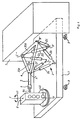
- FIG. 2 shows an embodiment of the coordinate measuring machine, with six legs on the base plate (1) (2a, 2b, 2c, 2d, 2e, 2f) are provided. Two legs each are in the area of the points (A ', B', C ') on the base plate (1) in adjacent ball joints, as in Fig. 3 for the leg (2a) shown, arranged. The camps two each Legs are close together, but this is not mandatory is. From each point area (A ', B', C ') is included Pair of legs (2a, 2b; 2c, 2d; 2e, 2f). One of the legs each pair is to a corner area (A ") of the body (4) led, the other leg (2b) of the couple to the corner area (B ") of the body (4). The legs stored in the area (B ') (2c and 2d) are arranged such that the leg (2c) in Area of the point (B ") is connected to the body (4) and the leg (2d) in the area of the point (C ") with this Body
- a corresponding arrangement is for the pair of legs (2e, 2f) hit by one of the legs, namely the leg (2e), connected to the body (4) in the area of the point (C ") and the other leg (2f) with the body (4) in the Area of point (A ").
- the body (4) forms a rod (35a, 35b and 35c) existing triangular frame.
- the poles (35a, 35b, 35c) are firmly connected. They wear a boom (5) to which the probe (6) is attached.
- By changing the length of the legs (2a to 2f) one can the base plate (1) arranged workpiece (8) in one Measuring point can be touched.
- the base plate (1) therefore consists of a thermal insensitive material and has a strength that Bends and linear expansion of the base plate (1) excluded are.
- measuring devices can also be provided be, which constantly the location of the articulation points of the Legs on the base plate (1) in the area of the points (A ', B' and C ') and check any positional deviations in this way Convert that corrections are made to the measured values can be. The same goes for those in the fields (A ", B", C ") legs articulated on the body (4).
- the base plate (1) can consist of several Parts exist, but then put them back together at the measuring location are (not shown).
- Base plate (1) To avoid unwanted changes in length of the legs (2) to cause by vibrations or the like is Base plate (1) according to FIG. 2 on damping elements (9), for example, hydraulically operating shock absorbers.
- the controller (not shown in Fig. 2) calculates the change in length of the legs to that desired by the operator Coordinates around and thus allows a movement of the Probe along Cartesian coordinate axes during deflection a control lever.
- the connection to the evaluation computer takes place as with conventional coordinate measuring machines.
- legs can also determine the change in Kick the angular position of at least one leg (not shown).
- the workpiece (8) to be measured is open a turntable (40) carried by the base plate (1) arranged around the axis (F-F) in the direction of the arrow (41) is rotatable.
Landscapes
- Physics & Mathematics (AREA)
- General Physics & Mathematics (AREA)
- A Measuring Device Byusing Mechanical Method (AREA)
- Length Measuring Devices With Unspecified Measuring Means (AREA)
Description
Die Erfindung betrifft eine Koordinatenmeßmaschine.The invention relates to a coordinate measuring machine.
Zum Anfahren eines Meßpunktes, beispielsweise auf einem Werkstück, in den kartesischen Koordinatenrichtungen bestehen die sogenannten 3-D-Koordinatenmeßmaschinen aus einem Stativ, dem Tastsystem, einer vorzugsweise separat angeordneten Versorgungs- und Steuereinheit und einem Auswerterechner. Das Stativ hat die Aufgabe, das Tastsystem relativ zum Werkstück meßbar zu bewegen. Diese Aufgabe wird nach dem Stand der Technik durch drei senkrecht aufeinanderstehende Linearachsen gelöst, von denen entweder zwei bei Koordinatenmeßmaschinen mit bewegtem Meßtisch oder drei bei Koordinatenmeßmaschinen mit feststehendem Meßtisch meßtechnisch und konstruktiv aufeinander aufbauen. To approach a measuring point, for example on a workpiece, in the Cartesian coordinate directions consist of the so-called 3-D coordinate measuring machines a tripod, the touch probe, one preferably separately arranged supply and control unit and an evaluation computer. The tripod has the task, the touch probe move measurably relative to the workpiece. This task will according to the prior art by three perpendicular to each other Linear axes solved, of which either two for coordinate measuring machines with a moving measuring table or three in coordinate measuring machines with a fixed measuring table and constructively build on each other.
Das Werkstück läßt sich aber auch, wie in der DE-OS 44 03 901 A1 beschrieben worden ist, mit einem Gerät antasten, das von einem Gelenkarm-Roboter abgeleitet ist.The workpiece can also, as in the DE-OS 44 03 901 A1 has been described with one device probe that is derived from an articulated arm robot.
Die bekannten Bewegungsmittel einer Koordinatenmeßmaschine nach der eingangs beschriebenen Art sind aufwendig. Denn jede Achse für die Verschiebung des Tastkopfes in einer Koordinatenrichtung enthält einen Antrieb, ein Maßstabsystem und eine Führung. Die Aufgabe der Führung ist es, Geradheits- und rotatorische Abweichungen bei Verschiebung des Tasters zu verhindern oder reproduzierbar und damit maschinenbedingt korrigierbar zu gestalten, und zwar mit einer sehr hohen Genauigkeit und unter allen zulässigen Temperatur- und Belastungsbedingungen. Beispielsweise muß bei einer Koordinatenmeßmaschine in Portalbauweise mit einer Meßlänge von einem Meter in allen drei Achsen die rotatorische Führungsgenauigkeit jeder Achse weit unter 0,5 Sekunden liegen, um eine Meßgenauigkeit im Bereich von 2 µm erreichen zu können. Aufgrund dieser Anforderungen liegt der größte Teil der Herstellungskosten einer Achse der Koordinatenmeßmaschine in der Führung und nicht im Antrieb oder dem Maßstabsystem.The known moving means of a coordinate measuring machine after the type described above are expensive. Because each axis for the displacement of the probe in one Coordinate direction contains a drive, a scale system and a tour. The task of leadership is es, straightness and rotational deviations when displaced to prevent the button or reproducible and thus to make it machine-correctable, namely with a very high accuracy and among all permissible Temperature and stress conditions. For example, must with a coordinate measuring machine in portal construction with a Measuring length of one meter in all three axes the rotary Guiding accuracy of each axis well under 0.5 seconds lie to a measuring accuracy in the range of 2 microns to be able to achieve. Because of these requirements most of the manufacturing cost of an axis of the coordinate measuring machine in the leadership and not in the drive or the scale system.
Mit den verfügbaren Meßmitteln ist bei den bekannten Koordinatenmeßmaschinen die Aufnahme von rotatorischen Ablauffehlern nur bis zu einer Genauigkeit von etwa 0,3 Sekunden möglich. Andererseits können Positionsfehler bis zu einer Genauigkeit von etwa 0,5 µm gemessen werden. Bei einer Koordinatenmeßmaschine mit großem Meßvolumen wird daher die erreichbare geometrische Genauigkeit oft durch die Aufnahmegenauigkeit der rotatorischen Abweichungen begrenzt.With the available measuring equipment is in the known Coordinate measuring machines the recording of rotatory sequence errors only to an accuracy of about 0.3 seconds possible. On the other hand, position errors can be up to an accuracy of about 0.5 µm can be measured. At a Coordinate measuring machine with a large measuring volume is therefore the achievable geometric accuracy often through the accuracy of the recording the rotational deviations are limited.
Bei den bekannten Koordinatenmeßmaschinen mit ruhendem Meßtisch bauen alle drei Achsen, das heißt die X-, Y- und Z-Achse bei der Verschiebung des Tastkopfes aufeinander auf, das heißt, alle Elemente der dritten Achse (Z-Achse) müssen von der zweiten Achse (Y-Achse) mitbewegt werden, und alle Elemente der zweiten Achse (Y-Achse) und der dritten Achse (Z-Achse) müssen von der ersten Achse (X-Achse) mitbewegt werden.In the known coordinate measuring machines with stationary Measuring table build all three axes, that is, the X, Y and Z axis when moving the probe towards each other on, that is, all elements of the third axis (Z axis) must be moved by the second axis (Y axis), and all elements of the second axis (Y axis) and the third axis (Z axis) must be from the first axis (X axis) be moved.
Bei Meßmaschinen mit bewegtem Meßtisch bauen nur zwei Achsen, nämlich die Y- und die Z-Achse, aufeinander auf, zusätzlich muß jedoch das Werkstück mit Hilfe des das Werkstück tragenden Tisches in der X-Achse bewegt werden.In measuring machines with a moving measuring table, only two build Axes, namely the Y and Z axes, on top of each other, in addition, however, the workpiece must be made using the workpiece supporting table can be moved in the X-axis.
In beiden Fällen sind bei den Koordinatenmeßmaschinen, welche den Tastkopf in den kartesischen Koordinatenrichtungen verschieben, große Massen zu bewegen, was eine Koordinatenmeßmaschine konventioneller Bauweise teuer und langsam macht.In both cases, the coordinate measuring machines which the probe in the Cartesian coordinate directions move, large masses move what a Coordinate measuring machine of conventional design expensive and slowly.
Die drei linearen Achsen einer zum Stand der Technik gehörenden Koordinatenmeßmaschine ermöglichen es jedoch, mit einer relativ einfachen Steuerung eine zu sich selbst parallele Verschiebung des Tastkopfes zu erreichen. Soll, wie etwa bei optischer Antastung oder auch bei bestimmten mechanischen Meßaufgaben der Tastkopf gedreht werden, so ist eine Dreh-Schwenkeinrichtung erforderlich, die zusätzliche Ungenauigkeiten, Kosten- und Steuerungsaufwand verursacht, auch wenn oft nur ein geringer Schwenkbereich wirklich erforderlich ist.The three linear axes one of the prior art belonging coordinate measuring machine make it possible, however, with a relatively simple control one to yourself to achieve parallel displacement of the probe. Should, such as with optical probing or with certain mechanical measuring tasks of the probe are rotated, so a rotary swivel device is required, the additional Causes inaccuracies, cost and control effort, even if often only a small swivel range really is required.
Jede Linearachse einer Koordinatenmeßmaschine erfordert eine sorgfältige Paralleljustage von Führung, Antrieb und Maßstab sowie Hilfskonstruktionen, wie etwa einen Schutz der Führungsflächen gegen Verschmutzung, ferner reibungsarme Schlauch- und Kabelführungen. Each linear axis requires a coordinate measuring machine careful parallel adjustment of the guide and drive and scale as well as auxiliary constructions, such as one Protection of the guide surfaces against dirt, also low-friction Hose and cable guides.
Die Gelenkarm-Meßmaschinen nach der DE-OS 44 03 901 A1 haben keine Linearachsen und vermeiden damit einen Teil des vorgenannten prinzipbedingten Aufwandes. Jedoch bauen auch bei dieser Bauart alle Achsen aufeinander auf, was zu relativ großen zu bewegenden Massen führt, insbesondere wenn ein aufwendiger Tastkopf eingesetzt werden soll. Thermische oder durch Lastwechsel bedingte Verbiegungen der Arme wirken sich auf die Genauigkeit der Messung aus. Die Auflösung verfügbarer Drehgeber ist für eine Genauigkeit im µm-Bereich nicht ausreichend. Koordinatenmeßmaschinen in Gelenkarm-Bauart sind hinsichtlich ihrer Leistungsfähigkeit daher noch weit von den beschriebenen Koordinatenmeßmaschinen konventioneller Bauart entfernt.The articulated arm measuring machines according to DE-OS 44 03 901 A1 have no linear axes and thus avoid part of the the aforementioned principle-related effort. However, build too With this design, all axes on each other, which is too relative leads to large masses to be moved, especially if a complex probe is to be used. thermal or bending of the arms caused by load changes the accuracy of the measurement. The resolution Available encoder is for accuracy in the µm range unsatisfactory. Coordinate measuring machines in Articulated arm design are in terms of their performance therefore still far from the coordinate measuring machines described conventional design removed.
Koordinatenmeßmaschinen müssen regelmäßig überprüft werden, um die Einhaltung der spezifizierten Genauigkeit nachzuweisen. Hierfür können kalibrierte Prüfkörper benutzt werden, beispielsweise Endmaße oder Kugelplatten. Es ist aber auch möglich, durch ein unabhängiges Meßsystem die Position des Tastkopfes zu überprüfen.Coordinate measuring machines must be checked regularly to ensure compliance with the specified accuracy demonstrated. Calibrated test specimens can be used for this such as gauge blocks or spherical plates. It is but also possible through an independent measuring system Check the position of the probe.
Um die Richtigkeit der Koordinaten des angetasteten Meßpunktes bestätigt zu erhalten, ist es aus der DD 141 061 bekannt, den Tastkopf in bekannter Weise koordinatenmäßig zu verschieben, mit dem Tastkopf jedoch zusätzlich, sozusagen zur Kontrolle, um feste Punkte neigbare Stangen vorzusehen, deren freie Enden mit dem Tastkopf allseitig drehbar verbunden sind, und die Stangen in ihrer Länge meßbar, verstellbar auszubilden. Wird der Tastkopf maschinell nach den vorgegebenen kartesischen Koordinaten verschoben, kann man durch Messung der Längen der ausziehbaren Stangen des Kontrollsystems prüfen, ob Meß- und/oder Verschiebefehler vorliegen, indem man aus den Längenänderungen der Stangen die Lage des angetasteten Meßpunktes ein zweites Mal berechnet und Einstellwert und Meßwert miteinander vergleicht. Bei dieser Ausbildung läßt sich nur vermuten, welcher der beiden Werte der richtige Wert ist, oder es kann ein Mittelwert aus den beiden Werten gebildet werden. Diese Ausbildung ist sehr aufwendig, da sie neben der Koordinatenmeßmaschine eine zusätzliche Meßeinrichtung als Kontrollsystem erfordert.To the correctness of the coordinates of the probed To get the measuring point confirmed, it is from DD 141 061 known to coordinate the probe in a known manner move, but additionally with the probe, as a control, so to speak, rods tiltable to fixed points provide the free ends of the probe on all sides are rotatably connected, and the rods in length measurable, adjustable training. The probe becomes machine according to the given Cartesian coordinates can be moved by measuring the lengths of the extendable Check the rods of the control system whether measuring and / or Displacement errors exist by looking at the length changes the position of the probed measuring point calculated a second time and set value and measured value together compares. With this training it can only be assumed which of the two values is the correct value, or an average can be formed from the two values. This training is very complex because it is in addition to the Coordinate measuring machine as an additional measuring device Control system required.
Ein entsprechendes Kontrollverfahren wird gemäß der DE 35 04 464 C1 für die Ermittlung der Positioniergenauigkeit einer Werkzeugaufnahme vorgenommen, bei der das Werkzeug durch einen Roboter verfahren wird. Dieses Kontrollgerät ist als transportables Gerät ausgebildet.A corresponding control procedure is carried out according to the DE 35 04 464 C1 for determining the positioning accuracy made a tool holder in which the Tool is moved by a robot. This Control device is designed as a portable device.
Aus der WO-A-91/03145 ist eine Werkzeugmaschine mit sechs Achsen bekannt, die eine untere Plattform und eine obere Plattform aufweist. Auf der unteren Plattform wird in dem von den Beinen begrenzten Raum das Werkstück angeordnet. Die obere Plattform trägt ein Werkzeug, beispielsweise ein spanabhebendes werkzeug oder einem Tastkopf.WO-A-91/03145 is one Machine tool known with six axes, the lower one Has platform and an upper platform. On the lower one Platform is in the space delimited by the legs arranged the workpiece. The upper platform enters Tool, for example a cutting tool or a probe.
Die beiden Plattformen sind mit sechs beweglichen und in ihrer Länge verstellbaren Beinen miteinander verbunden.The two platforms are with six movable and Legs adjustable in length joined together.
Diese zum Stand der Technik gehörende Werkzeugmaschine hat den Nachteil, dass das Werkstück in dem von den Beinen begrenzten Raum angeordnet ist. Hierdurch können lediglich Werkstücke mit begrenzter räumlicher Ausdehnung in dieser zum Stand der Technik gehörenden Werkzeugmaschine bearbeitet werden. Die Werkstücke können nicht größer als der von den Beinen und den beiden Plattformen begrenzte Raum sein. This machine tool belonging to the state of the art has the disadvantage that the workpiece in the of the legs limited space is arranged. This can only Workpieces with limited spatial expansion in this machined machine tool belonging to the prior art become. The workpieces cannot be larger than that of the legs and the two platforms be limited space.
Baubedingt durch den begrenzten Raum zwischen den Plattformen und den Beinen ist das Werkzeug in kurzem Abstand zu der oberen Plattform angeordnet, um einen möglichst großen Arbeitsraum zu erhalten.Due to the limited space between the Platforms and legs is the tool in a nutshell Distance to the upper platform arranged to be as possible to get large work space.
WO-A-91/14905 beschreibt ein Positionsmeßgerät, welches wie die oben genannte Werkzeugmaschine (WO-A-91/03145) sechs Achsen aufweist, die eine untere Plattform mit einer oberen Plattform verbinden.WO-A-91/14905 describes a position measuring device, which like the machine tool above (WO-A-91/03145) has six axes, a lower one Connect the platform to an upper platform.
Gemäß der WO-A-95/14905 wird das zu vermessende Werkstück zwischen den Beinen des Positionsmeßgerätes angeordnet und mit einem Taster vermessen. Gemäß einem Ausführungsbeispiel dieses Standes der Technik ist das Werkstück zwar nicht zwischen den Beinen angeordnet, jedoch nach wie vor innerhalb einer Rahmen und Trägerkonstruktion des Positionsmeßgerätes (Fig. 11). Die Anordnung des Werkstückes innerhalb des von den Beinen gebildeten Raumes und/oder innerhalb der Träger und Rahmenkonstruktion des Koordinatenmeßgerätes hat den schon genannten Nachteil, daß der Raum für die Aufnahme des Werkstückes eine begrenzte räumliche Ausdehnung aufweist, so dass Werkstücke lediglich bis zu einer Maximalgröße in diesem zum Stand der Technik gehörenden Positionsmeßgerät vermessen werden können. Darüber hinaus ist eine freie und ungehinderte manuelle oder automatische Beschickung des Koordinatenmeßgerätes gemäß diesem Stand der Technik nicht möglich.According to WO-A-95/14905, the workpiece to be measured is arranged between the legs of the position measuring device and measure with a button. According to one embodiment this state of the art is the workpiece not arranged between the legs, but still in front of a frame and support structure of the position measuring device (Fig. 11). The arrangement of the workpiece within the space formed by the legs and / or within the support and frame construction of the coordinate measuring machine has the disadvantage already mentioned that the Space for receiving the workpiece is a limited spatial Has expansion, so that workpieces only up to to a maximum size in this state of the art belonging position measuring device can be measured. It is also a free and unobstructed manual or automatic loading of the coordinate measuring machine not possible according to this state of the art.
Das der Erfindung zugrunde liegende technische Problem besteht darin, eine Koordinatenmeßmaschine anzugeben, welche von ihrem Grundaufbau einfach und preiswert herstellbar ist, darüber hinaus jedoch die gewünschte Meßgenauigkeit und -geschwindigkeit gewährleistet und insbesondere auch schwierig erreichbare Meßpunkte leicht antasten läßt.The technical problem underlying the invention consists in specifying a coordinate measuring machine which easy and inexpensive to manufacture from its basic structure is, however, the desired measurement accuracy guaranteed and speed and in particular also difficult to reach measuring points.
Diese Aufgabe wird durch das kennzeichnende Merkmal
des Anspruches 1 gelöst.This task is characterized by the characteristic
of
Dadurch, daß das aus der DD 141 061 an sich bekannte Prinzip der Kontrollmessung erfindungsgemäß dazu verwendet wird, den Tastkopf zu tragen und meßgenau zu bewegen, kann, wie gefunden wurde, die bisherige, aus den genannten Gründen aufwendige Standard-Koordinatenmeßmaschine des Tastkopfes vollkommen entfallen, insbesondere da der Tastkopf gewichtsmäßig relativ leicht ist und deshalb zu seiner exakten Verschiebung nicht des massigen Aufbaus der bisherigen Koordinatenmeßmaschine bedarf.Because that known from DD 141 061 Principle of the control measurement used for this purpose according to the invention can carry the probe and move it precisely, as found, the previous one, for the reasons mentioned elaborate standard coordinate measuring machine of the probe completely eliminated, especially since the probe is relatively light in weight and therefore to his exact shift not the massive structure of the previous Coordinate measuring machine needed.
Dadurch, daß jetzt der Tastkopf von einem Körper getragen wird, der als gewichtsmäßig relativ leichtes Rahmengestell ausgebildet sein kann, und vorteilhaft wenigstens ein Punkt des Körpers mittels in der Länge und/oder den Winkeln verstellbarer Beine in vorgegebenen Fixpunkten mit der das Werkstück tragenden Grundplatte gelenkig verbunden ist, ist es möglich, den vom Körper getragenen Tastkopf im Meßbereich der Koordinatenmeßmaschine beispielsweise allein durch Veränderung der Länge der Beine an jeden beliebigen Ort zu fahren. Aus der gemessenen Länge der Beine kann ein Rechner leicht die Position der Tastspitze des Tastkopfes ermitteln und in kartesischen Koordinaten angeben.Because now the probe is carried by a body is that as a relatively light weight frame can be formed, and advantageously at least a point of the body by means of length and / or the angles of adjustable legs in predetermined fixed points articulated to the base plate carrying the workpiece it is possible to use the probe worn by the body in the measuring range of the coordinate measuring machine, for example just by changing the length of the legs to everyone any place to drive. From the measured length of the legs a calculator can easily determine the position of the probe tip Determine the probe and in Cartesian coordinates specify.
Ein starrer Körper im Raum besitzt sechs Freiheitsgrade, nämlich drei translatorische und drei rotatorische Freiheitsgrade. Um die Lage des Tastkopfes eindeutig festzulegen, sind daher sechs einschränkende Bedingungen notwendig.A rigid body in space has six degrees of freedom, namely three translational and three rotatory Degrees of freedom. In order to clearly define the position of the probe, therefore six restrictive conditions are necessary.
Deshalb hat es sich als vorteilhaft erwiesen, sechs Beine vorzusehen, von denen jedoch nicht alle in ihrer Länge verstellbar sein müssen. Mindestens drei der Beine müssen aber gelenkig und längenverstellbar sein.That's why it turned out to be beneficial, six Legs, but not all of them in their Length must be adjustable. At least three of the legs but must be articulated and adjustable in length.
Die Beine brauchen im Ausgangszustand nicht gleiche Länge aufzuweisen. Vorteilhaft wird man die Beine jedoch in gleicher Bauart ausbilden, um diese in Serienfertigung herstellen zu können. The legs do not need the same in the initial state Show length. It is advantageous to have your legs in train the same type to manufacture them in series production to be able to.
Sechs Beine lassen sich in bekannter Weise in einer Hexapoden-Bauart anordnen.Six legs can be combined in a known manner Arrange the hexapod type.
Regelmäßige Hexapoden-Bauarten sind grundsätzlich aus
den Veröffentlichungen der Zeitschrift "Spektrum der
Wissenschaft" vom Mai 1991, Seiten 18 bis 22 sowie aus der
Zeitschrift "Schweizer Maschinenmarkt", Nr. 17/1995, Seiten
26 bis 29 bekannt. Bei derartigen auf einer Grundplatte und
einer starren Gehäusekonstruktion in Leichtbauweise
aufbauenden Körpern geht man davon aus, daß ein Dreieck und
die darauf basierenden Körper, zum Beispiel Tetraeder,
Oktaeder oder Ikosaeder, dann, wenn sie nur an den Ecken
belastet werden, die größte Steifigkeit aufweisen. Demgemäß
weist die in der Zeitschrift "Spektrum der Wissenschaft"
vom Mai 1991 vorgesehene Hexapoden-Bauart sechs regelmäßig
angeordnete Beine auf, welche dazu dienen, den Hauptspiegel
eines Spiegelteleskopes für astronomische Zwecke zu tragen
und der Erddrehung nachzuführen. Dieser geplante Spiegel
soll wenigstens einen Durchmesser von 12 m aufweisen und
ist deshalb gewichtsmäßig sehr schwer. Die für seine
Lagerung vorgesehene Hexapoden-Bauart ist deshalb einzig
und allein darauf ausgelegt, einen gewichtsmäßig schweren
Gegenstand zu tragen und nachzuführen.Regular hexapod types are basically out
the publications of the magazine "Spektrum der
Science "from May 1991, pages 18 to 22 and from the
Magazine "Schweizer Maschinenmarkt", No. 17/1995,
Dasselbe gilt für die im Maschinenbau angestrebte Technik, die Hexapoden-Bauart bei einer Werkzeugmaschine vorzusehen. Auch hier soll die Hexapoden-Bauart gestatten, große Kräfte auszuüben.The same applies to the one aimed at in mechanical engineering Technology, the hexapod design in a machine tool provided. Here too, the hexapod design should allow to exercise great powers.
Gemäß der Erfindung wird von den Beinen nur ein relativ leichtes Rahmengestell getragen, das seinerseits den Tastkopf trägt. Bei der erfindungsgemäßen Verstellung des Tastkopfes und des mit diesem verbundenen Tasters kommt es deshalb nur darauf an, mit einfachen Mitteln den Taster des Tastkopfes so zu bewegen, daß er mit µm-Genauigkeit auf den Meßpunkt des Werkstückes gefahren wird.According to the invention, only one of the legs becomes relative lightweight frame worn, which in turn the Probe carries. When adjusting the Probe and the button connected to it comes therefore only on the simple push of a button To move the probe so that it is accurate to the µm Measuring point of the workpiece is moved.
Als weiterhin vorteilhaft hat es sich erwiesen, den Tastkopf an einem Ausleger des mit Hilfe der Stangenkonstruktion beweglichen Körpers anzuordnen.It has also proven to be advantageous that Probe on an arm of the with the help of To arrange rod construction movable body.
Typische Werkstücke von Koordinatenmeßmaschinen sind oft etwa quaderförmig, wobei an mehreren ihrer sechs Seiten spezielle Strukturen, wie etwa Bohrungen, eingelassen sind, deren geometrische Merkmale von der Meßmaschine zu bestimmen sind. Dabei ist es stets das Bestreben, mit möglichst kurzen Tastern zu arbeiten, da lange Taststiftkombinationen unhandlich sind, bei vielen Tastköpfen aufgrund des Gewichtes nicht verwendet werden können und zu Genauigkeitseinbußen und Einschränkungen der Verfahrgeschwindigkeit führen.Typical workpieces of coordinate measuring machines are often roughly cuboid, with several of its six sides special structures, such as holes, are embedded, to determine their geometric characteristics from the measuring machine are. It is always the aim, if possible short buttons work because of long stylus combinations are unwieldy due to the weight of many probes can not be used and loss of accuracy and travel speed limitations to lead.
Deshalb ist bei Koordinatenmeßmaschinen kartesischer Bauart die "oberste" der Achsen in der kinematischen Kette als verschiebbarer Ausleger, in der Regel mit mitbewegten Führungselementen ausgeführt (Pinole). Dieser Ausleger muß einschließlich aufbauender Zusatzkonstruktionen, wie etwa Führung, Maßstab oder Kollisionsschutz, einen möglichst geringen Querschnitt haben, da dieser beim Antasten von Merkmalen an den Seitenflächen des Werkstückquaders in die Tasterlänge eingeht. Bei dieser Bauweise ergibt sich außerdem häufig das Problem, daß der Maßstab konstruktionsbedingt etwa aus Platzgründen auf der Pinole angebracht werden muß und dann in ausgefahrener Stellung der Pinole freiliegt und ungeschützt Verschmutzungen und thermischen Störungen ausgesetzt ist. Therefore it is more Cartesian in coordinate measuring machines Build the "top" of the axes in the kinematic chain as a movable boom, usually with moving ones Guiding elements executed (quill). This boom must including additional structures such as Leadership, scale or collision protection, the lowest possible Have a cross-section as this is when probing features on the side surfaces of the workpiece cuboid in the probe length received. This construction also results often the problem that the scale is design-related for space reasons must be attached to the quill and then exposed in the extended position of the quill and exposed to contamination and thermal interference is.
Bei einer Koordinatenmeßmaschine in der erfindungsgemäßen Bauart ist aus den genannten Gründen die Anbringung des Tastkopfes direkt an dem von den Beinen getragenen Rahmengestell nicht erwünscht. Es ist daher der Tastkopf am Ende eines mit dem Rahmengestell starr verbundenen Auslegers angebracht. Dieser Ausleger hat, im Gegensatz zur konventionellen Bauart, keine Führungsfunktion und kann daher mit einem für die Steifigkeit und für die Verwendbarkeit kurzer Taster optimierten, eventuell sich verjüngenden Querschnitt konstruiert werden. Der Ausleger trägt bei der erfindungsgemäßen Bauart auch keinen Maßstab oder andere empfindliche Teile, die vor Verschmutzung geschützt werden müssen. Der Ausleger sollte gegen thermische Störungen unempfindlich sein.In a coordinate measuring machine in the invention Construction is the attachment for the reasons mentioned of the probe head directly on the frame supported by the legs not wanted. It is therefore the probe on End of a boom rigidly connected to the frame appropriate. In contrast to the conventional design, no management function and can therefore with one for the rigidity and for the Use of short buttons optimized, possibly yourself tapered cross section. The boom does not carry a scale in the design according to the invention or other sensitive parts that are protected from contamination Need to become. The boom should be against thermal Be insensitive to interference.
Ein weiterer Vorteil der erfindungsgemäßen Ausbildung ist, daß die Grundplatten, die Beine und der den Tastkopf tragende Körper in einem Gehäuse anordbar sind, aus dem der den Meßkopf tragende Ausleger herausragt. Hierdurch wird eine weitestgehende Abschirmung der die Bewegung auslösenden und registrierenden Elemente (Beine) und ihrer Lager gegen Verschmutzung und äußere thermische Einflüsse erreicht.Another advantage of the training according to the invention is that the base plates, the legs and the the probe load-bearing body can be arranged in a housing from which the the arm supporting the measuring head protrudes. This will the greatest possible shielding of the movement and registration elements (legs) and their bearings against pollution and external thermal influences reached.
Ein weiterer Vorteil der erfindungsgemäßen Ausbildung
ist, daß die Aufnahme für das auszumessende Werkstück
außerhalb des von den Beinen beanspruchten Raumes angeordnet
sein kann, so daß eine ungehinderte manuelle oder
automatische Beschickung des Koordinatenmeßgerätes möglich
ist. Der Bediener kann dann auch, wie es etwa beim
Erstellen eines neuen Meßlaufes notwendig ist, aus kurzer
Entfernung den Antastpunkt beobachten; wäre der Tastkopf,
wie aus der Zeitschrift "Schweizer Maschinenmarkt",
Nr. 17/1995, Seiten 26 bis 29 für den Werkzeugkopf bekannt,
innerhalb des von den Beinen umschlossenen Raumes
angeordnet, so wäre dies aus Zugänglichkeits- und Sicherheitsgründen
ausgeschlossen. Die an Werkzeugmaschinen gestellte
Forderung nach der Aufnahme großer Kräfte, wobei
ein Ausleger von Nachteil wäre, besteht bei Koordinatenmeßgeräten
nicht, da die beim Antasten ausgeübten Kräfte
klein und darüber hinaus meßbar und damit korrigierbar
sind.Another advantage of the training according to the invention
is that the holder for the workpiece to be measured
arranged outside the space occupied by the legs
can be so that an unimpeded manual or
automatic loading of the coordinate measuring machine possible
is. The operator can then, as is the case with
Creating a new measuring run is necessary from short
Observe the touch point from a distance; would be the probe
like from the magazine "Schweizer Maschinenmarkt",
No. 17/1995,
Die erfindungsgemäße Ausbildung erlaubt es auch, die Aufnahme für das auszumessende Werkstück auf einfache Weise, beispielsweise durch Lösen einer Schraubverbindung, von der Grundplatte zu trennen und wechselbar zu gestalten. Damit kann ein ortsfest aufgestelltes Koordinatenmeßgerät mit verschiedenen Werkstückaufnahmen ausgestattet werden oder ein für häufige Ortswechsel ausgelegtes Koordinatenmeßgerät, beispielsweise ortsfeste Werkstückaufnahmen angeschlossen werden.The training according to the invention also allows the Recording for the workpiece to be measured on simple Way, for example by loosening a screw connection, to separate from the base plate and make it interchangeable. This allows a stationary coordinate measuring machine can be equipped with various workpiece holders or a coordinate measuring machine designed for frequent changes of location, for example, fixed workpiece holders connected become.
Der Tisch für die Aufnahme des Werkstückes kann auch als Drehtisch ausgebildet sein, oder es kann ein derartiger Drehtisch auf der Grundplatte vorgesehen sein. Der Drehtisch kann hierbei kontinuierlich um eine vertikal auf der Grundplatte stehende Achse drehbar sein oder aber auch in Intervallen.The table for holding the workpiece can also be designed as a turntable, or such Rotary table may be provided on the base plate. The turntable can be continuously adjusted vertically on the Base plate standing axis can be rotated or in Intervals.
Weitere Einzelheiten der Erfindung können den obhängigen Ansprüchen entnommen werden.Further details of the invention can be found in the foregoing Claims are taken.
Auf der Zeichnung ist ein Ausführungsbeispiel der Erfindung dargestellt, und zwar zeigen:
- Fig. 1
- eine schematische Darstellung zur Erläuterung der Wirkungsweise;
- Fig. 2
- eine schematische Darstellung der Koordinatenmeßmaschine;
- Fig. 3
- eine Einzelheit der Fig. 1;
- Fig. 4
- eine geänderte Ausbildung nach Fig. 2.
- Fig. 1
- a schematic representation to explain the mode of operation;
- Fig. 2
- a schematic representation of the coordinate measuring machine;
- Fig. 3
- a detail of Fig. 1;
- Fig. 4
- a modified training according to Fig. 2nd
Gemäß Fig. 1 sind auf einer Grundplatte (1) in den Punkten (A, B, C) Kugelgelenke (3a, 3b und 3c) vorgesehen, in denen Beine (2a, 2b und 2c) allseitig drehbar gelagert sind. Die Beine (2a, 2b, 2c) laufen in einem Punkt (D) zusammen oder in seiner unmittelbaren Nähe. Sie sind jeweils gelenkig im Bereich des Punktes (D) miteinander verbunden. Die Beine (2a, 2b, 2c) weisen die Längen L1, L2 und L3 auf.1, ball joints (3a, 3b and 3c) are provided on points (A, B, C) on a base plate (1), in which legs (2a, 2b and 2c) are rotatably mounted on all sides. The legs (2a, 2b, 2c) converge at a point (D) or in its immediate vicinity. They are articulated in the area of point (D). The legs (2a, 2b, 2c) have the lengths L 1 , L 2 and L 3 .
Wird der Punkt (D), welcher den Tastkopf (6) der Fig. 2 tragen kann, nach (D') verschoben, wandert das Bein (2a) in die Lage (2a'), das Bein (2b) in die Lage (2b') und das Bein (2c) in die Lage (2c'). Damit diese Lageänderung des Punktes (D) nach (D') möglich ist, müssen sich die Längen der Beine (2a, 2b, 2c) ändern. Die Länge L1 des Beines (2a) ändert sich um den Betrag dL1, die Länge des Beines (2b) ändert sich um den Betrag dL2 und die Länge des Beines (2c) ändert sich um den Betrag dL3.If point (D), which can carry the probe (6) of FIG. 2, is moved to (D '), leg (2a) moves into position (2a'), leg (2b) into position ( 2b ') and the leg (2c) in position (2c'). The lengths of the legs (2a, 2b, 2c) must change so that this change in position of point (D) to (D ') is possible. The length L 1 of the leg (2a) changes by the amount dL 1 , the length of the leg (2b) changes by the amount dL 2 and the length of the leg (2c) changes by the amount dL 3 .
Diese Längenänderungen der Beine (2a, 2b, 2c) können, wie noch zu zeigen sein wird, bewußt erzeugt werden, um den im Punkt (D) angelenkten Tastkopf (6) nach (D') zu verlagern. These changes in length of the legs (2a, 2b, 2c) can as will be shown, are deliberately created in order to at point (D) articulated probe (6) to move to (D ').
Eine solche Verlagerung kann aber auch grundsätzlich von Hand oder durch andersartige Mittel durchgeführt werden.Such a shift can also be fundamentally be carried out by hand or by other means.
In jedem Fall ist es erforderlich, die Längenänderung der Beine (2a, 2b, 2c) zu erfassen.In any case, it is necessary to change the length of the legs (2a, 2b, 2c).
Die bei der Verlagerung des Punktes (D) nach (D') erfolgenden Winkeländerungen der Beine in den Anlenkpunkten (A, B, C) auf der Grundplatte (1) oder im Punkt (D) eines Körpers (4) (Fig. 3) sind hierbei dann ohne Bedeutung, wenn die Längenänderungen dL1, dL2, dL3 meßbar sind, da die Lage eines jeden Punktes im Raum durch drei Koordinaten bestimmt wird, hier also durch die Längen der Beine (2a, 2b, 2c) in ihrer Ausgangslage in den Punkten (A, B und C) auf der Grundplatte (1) und bei Verlagerung des Punktes (D) nach (D').The changes in the angle of the legs in the articulation points (A, B, C) on the base plate (1) or in point (D) of a body (4) when the point (D) is moved to (D ') (FIG. 3) are of no importance here if the changes in length dL 1 , dL 2 , dL 3 can be measured, since the position of each point in space is determined by three coordinates, here by the lengths of the legs (2a, 2b, 2c) in their Starting point at points (A, B and C) on the base plate (1) and when point (D) is moved to (D ').
Anstelle der Längenänderungen können aber auch Winkeländerungen der Beine zur Grundplatte für die Bestimmung der Lageänderung des Punktes (D) nach (D') verwendet werden.Instead of length changes, you can also Changes in the angle of the legs to the base plate for the Determination of the change in position of point (D) according to (D ') be used.
Gemäß Fig. 3 sind die Beine, wie für das Bein (2a) gezeigt, ausfahrbar ausgebildet. Auf der Grundplatte (1) ist im Punkt (A) mittels eines Kugelgelenks (25) das Bein (2a) allseitig schwenkbar gelagert. Das Bein besteht aus einem zylinderförmigen Teil (26), in dem ein Kolben (27) verschiebbar gelagert ist. Der Kolben (27) trägt eine Kolbenstange (28). Die Kolbenstange (28) ist mittels eines Kugelgelenks (29) an dem noch zu beschreibenden Körper (4) der Fig. 2 befestigt. Der Körper (4) kann, so wie es für den Punkt (D) in Fig. 1 gezeigt wurde, in den drei kartesischen Koordinatenrichtungen verschoben werden. Das Bein (2a) ändert hierbei seine Winkelneigung zur Grundplatte (1) und auch zum Körper (4) (Fig. 1), außerdem aber auch seine Länge L1 mit Bezug auf die Mittelpunkte der Kugeln (25 und 29) der Kugelgelenke in den Punkten (A und D).3, the legs, as shown for the leg (2a), are designed to be extendable. On the base plate (1) at point (A), the leg (2a) can be pivoted on all sides by means of a ball joint (25). The leg consists of a cylindrical part (26) in which a piston (27) is slidably mounted. The piston (27) carries a piston rod (28). The piston rod (28) is fastened to the body (4) of FIG. 2 to be described by means of a ball joint (29). The body (4), as shown for the point (D) in Fig. 1, can be moved in the three Cartesian coordinate directions. The leg (2a) changes its angle to the base plate (1) and also to the body (4) (Fig. 1), but also its length L 1 with reference to the centers of the balls (25 and 29) of the ball joints in the Points (A and D).
Beispielsweise mit Hilfe eines Hydraulikmittels, welches über die Leitung (30) in den zylinderförmigen Teil (26) gedrückt wird, kann die Längenänderung des Beines (2a) gesteuert werden und damit die Verlagerung des Körpers (4).For example, with the help of a hydraulic medium, which via the line (30) into the cylindrical part (26) is pressed, the change in length of the leg (2a) can be controlled and thus the displacement of the body (4).
Eine Lagerung und Steuerung des Beines (2a), wie in Fig. 3 beschrieben, ist für jedes der drei Beine (2a, 2b und 2c) der Fig. 1 vorgesehen.Storage and control of the leg (2a) as in 3, is described for each of the three legs (2a, 2b and 2c) of FIG. 1.
Um die Größe der Längenänderung des Beines (2a) aus einer Normalstellung heraus zu erfassen, trägt der zylinderförmige Teil (26) einen Maßstab (31). Auf dem Maßstab (31) kann mittels eines Ableseindex (32), welcher über eine Stange (33) mit der Kolbenstange (28) im Punkt (E) verbunden ist, die Längenänderung des Beines (2a) abgelesen werden. Die Ausfahrgröße der Kolbenstange (28) und damit die Längenänderung dL1 des Beines (2a) entspricht der Verschiebungsgröße des Kolbens (27) und damit der Kolbenstange (28) des Körpers (4) im Anlenkpunkt des Kugelgelenks (29).In order to detect the size of the change in length of the leg (2a) from a normal position, the cylindrical part (26) carries a scale (31). The change in length of the leg (2a) can be read off on the scale (31) by means of a reading index (32) which is connected to the piston rod (28) at point (E) via a rod (33). The extension size of the piston rod (28) and thus the change in length dL 1 of the leg (2a) corresponds to the displacement size of the piston (27) and thus the piston rod (28) of the body (4) at the articulation point of the ball joint (29).
Die in Fig. 3 schematisch dargestellte Erfassung der Längenänderung dL1 kann mit modernen Mitteln sensorisch erfolgen und beispielsweise als Wert in eine nicht dargestellte Meß- und Steuereinrichtung eingegeben werden.The detection of the change in length dL 1 , shown schematically in FIG. 3, can be carried out by sensors using modern means and, for example, entered as a value in a measuring and control device (not shown).
Für jedes der drei Beine (2a, 2b, 2c) ist in der Fig. 1 eine entsprechende Einrichtung vorgesehen. For each of the three legs (2a, 2b, 2c) is in the Fig. 1 provided a corresponding device.
Aus den gemessenen Längenänderungen der Beine (2a, 2b, 2c) kann damit die Lage des Punktes (D) rechnerisch ermittelt werden oder umgekehrt durch Steuerungsmittel, welche die Kolben (26) geeignet verschieben, ein bestimmter Punkt, in Fig. 1 zum Beispiel der Punkt (D'), angefahren werden.From the measured changes in length of the legs (2a, 2b, 2c) can thus determine the position of point (D) by calculation or vice versa by control means which move the pistons (26) appropriately, a certain point, 1, for example, point (D ') can be approached.
Fig. 2 zeigt ein Ausführungsbeispiel der Koordinatenmeßmaschine, bei dem auf der Grundplatte (1) sechs Beine (2a, 2b, 2c, 2d, 2e, 2f) vorgesehen sind. Je zwei Beine sind in dem Bereich der Punkte (A', B', C') auf der Grundplatte (1) in benachbarten Kugelgelenken, wie in Fig. 3 für das Bein (2a) dargestellt, angeordnet. Die Lager je zweier Beine liegen dicht beieinander, was jedoch nicht zwingend ist. Von jedem Punktbereich (A', B', C') geht damit ein Beinpaar (2a, 2b; 2c, 2d; 2e, 2f) aus. Eines der Beine jeden Paares ist zu einem Eckbereich (A") des Körpers (4) geführt, das andere Bein (2b) des Paares zum Eckbereich (B") des Körpers (4). Die im Bereich (B') gelagerten Beine (2c und 2d) sind derart angeordnet, daß das Bein (2c) im Bereich des Punktes (B") mit dem Körper (4) verbunden ist und das Bein (2d) im Bereich des Punktes (C") mit diesem Körper.2 shows an embodiment of the coordinate measuring machine, with six legs on the base plate (1) (2a, 2b, 2c, 2d, 2e, 2f) are provided. Two legs each are in the area of the points (A ', B', C ') on the base plate (1) in adjacent ball joints, as in Fig. 3 for the leg (2a) shown, arranged. The camps two each Legs are close together, but this is not mandatory is. From each point area (A ', B', C ') is included Pair of legs (2a, 2b; 2c, 2d; 2e, 2f). One of the legs each pair is to a corner area (A ") of the body (4) led, the other leg (2b) of the couple to the corner area (B ") of the body (4). The legs stored in the area (B ') (2c and 2d) are arranged such that the leg (2c) in Area of the point (B ") is connected to the body (4) and the leg (2d) in the area of the point (C ") with this Body.
Eine entsprechende Anordnung ist für das Beinpaar (2e, 2f) getroffen, indem eines der Beine, nämlich das Bein (2e), mit dem Körper (4) im Bereich des Punktes (C") verbunden ist und das andere Bein (2f) mit dem Körper (4) im Bereich des Punktes (A").A corresponding arrangement is for the pair of legs (2e, 2f) hit by one of the legs, namely the leg (2e), connected to the body (4) in the area of the point (C ") and the other leg (2f) with the body (4) in the Area of point (A ").
Der Körper (4) bildet ein aus Stangen (35a, 35b und 35c) bestehendes dreieckförmiges Rahmengestell. Die Stangen (35a, 35b, 35c) sind fest miteinander verbunden. Sie tragen einen Ausleger (5), an dem der Tastkopf (6) befestigt ist. Durch Änderung der Länge der Beine (2a bis 2f) kann ein auf der Grundplatte (1) angeordnetes Werkstück (8) in einem Meßpunkt angetastet werden.The body (4) forms a rod (35a, 35b and 35c) existing triangular frame. The poles (35a, 35b, 35c) are firmly connected. they wear a boom (5) to which the probe (6) is attached. By changing the length of the legs (2a to 2f) one can the base plate (1) arranged workpiece (8) in one Measuring point can be touched.
Die Längenänderungen dL der Beine (2a bis 2f) werden rechnerisch erfaßt und in die Lage (X, Y, Z) der Tastspitze (6a) umgerechnet sowie zur Steuerung der Bewegung des Körpers (4) und des Tastkopfes (6) verwendet.The changes in length dL of the legs (2a to 2f) will be computed and in the position (X, Y, Z) of the probe tip (6a) converted and to control the movement of the body (4) and the probe (6) used.
Bei der beschriebenen Ausbildung kommt es im wesentlichen darauf an, daß die Anlenkpunkte der Beine auf der Grundplatte und dem Körper (4) einen konstanten Abstand voneinander aufweisen und stets beibehalten, das heißt, daß sich die Mittelpunkte der Kugeln der Kugelgelenke nicht gegeneinander verschieben. Ferner kommt es darauf an, daß sich die Länge der Beine (2a bis 2f) nicht unkontrollierbar ändert, weil dann ein angeschlossener Rechner eine Fehllage des Punktes (D) und damit der Tastspitze (6a) ermittelt. Die Grundplatte (1) besteht deshalb aus einem thermisch unempfindlichen Material und weist eine Stärke auf, daß Verbiegungen und Längenausdehnungen der Grundplatte (1) ausgeschlossen sind.In the training described, it essentially occurs on the fact that the articulation points of the legs on the Base plate and the body (4) a constant distance have from each other and always maintain, that is the centers of the balls of the ball joints do not move against each other. It is also important that the length of the legs (2a to 2f) is not uncontrollable changes because then a connected computer is in an incorrect position the point (D) and thus the probe tip (6a) determined. The base plate (1) therefore consists of a thermal insensitive material and has a strength that Bends and linear expansion of the base plate (1) excluded are.
Grundsätzlich können aber auch Meßeinrichtungen vorgesehen sein, welche ständig die Lage der Anlenkpunkte der Beine an der Grundplatte (1) im Bereich der Punkte (A', B' und C') kontrollieren und eventuelle Lageabweichungen derart umrechnen, daß an den Meßwerten Korrekturen angebracht werden können. Das gleiche gilt für die in den Bereichen (A", B", C") auf dem Körper (4) angelenkten Beine.Basically, however, measuring devices can also be provided be, which constantly the location of the articulation points of the Legs on the base plate (1) in the area of the points (A ', B' and C ') and check any positional deviations in this way Convert that corrections are made to the measured values can be. The same goes for those in the fields (A ", B", C ") legs articulated on the body (4).
Damit die Bewegungseinrichtung für den Taster, bestehend aus den Beinen (2a bis 2f) und dem Körper (4), nicht verschmutzt und auch gegen thermische Einflüsse weitgehend abgeschirmt ist, kann über dieser Bewegungseinrichtung ein Gehäuse (7) angeordnet sein.So that the movement device for the button, consisting from the legs (2a to 2f) and the body (4), not dirty and largely against thermal influences is shielded, can over this movement device Housing (7) may be arranged.
Für Transportzwecke kann die Grundplatte (1) aus mehreren Teilen bestehen, die dann jedoch am Meßort wieder zusammenzusetzen sind (nicht dargestellt).For transport purposes, the base plate (1) can consist of several Parts exist, but then put them back together at the measuring location are (not shown).
Um keine ungewollten Längenänderungen der Beine (2) durch Erschütterungen oder dergleichen zu bewirken, ist die Grundplatte (1) gemäß Fig. 2 auf Dämpfungselementen (9), beispielsweise hydraulisch arbeitenden Stoßdämpfern, angeordnet.To avoid unwanted changes in length of the legs (2) to cause by vibrations or the like is Base plate (1) according to FIG. 2 on damping elements (9), for example, hydraulically operating shock absorbers.
Die Steuerung (nicht dargestellt in Fig. 2) rechnet die Längenänderung der Beine in die vom Bediener gewünschten Koordinaten um und ermöglicht damit eine Bewegung des Tastkopfes entlang kartesischer Koordinatenachsen bei Auslenkung eines Steuerhebels. Der Anschluß an den Auswerterechner erfolgt wie bei konventionellen Koordinatenmeßmaschinen.The controller (not shown in Fig. 2) calculates the change in length of the legs to that desired by the operator Coordinates around and thus allows a movement of the Probe along Cartesian coordinate axes during deflection a control lever. The connection to the evaluation computer takes place as with conventional coordinate measuring machines.
Die erreichbare Genauigkeit kann durch eine rechnerische Korrektur der geometrischen Abweichungen gesteigert werden.The achievable accuracy can be calculated Correction of the geometric deviations increased become.
Anstelle einer Längenänderung der Beine oder eines der Beine kann aber auch die Ermittlung der Änderung der Winkellage wenigstens eines Beines treten (nicht dargestellt).Instead of changing the length of the legs or one of the But legs can also determine the change in Kick the angular position of at least one leg (not shown).
Gemäß Fig. 4 ist das auszumessende Werkstück (8) auf einem von der Grundplatte (1) getragenen Drehtisch (40) angeordnet, der um die Achse (F-F) in Richtung des Pfeiles (41) drehbar ist. 4, the workpiece (8) to be measured is open a turntable (40) carried by the base plate (1) arranged around the axis (F-F) in the direction of the arrow (41) is rotatable.
- 11
- Grundplattebaseplate
- 1a1a
- Platteplate
- 22
- Beinelegs
- 2a, 2b, 2c,2a, 2b, 2c,
- längenverstellbare Beineadjustable legs
- 2a', 2b', 2c'2a ', 2b', 2c '
- geänderte Lagen der Beine (2a, 2b, 2c)changed positions of the legs (2a, 2b, 2c)
- 2d, 2e, 2f2d, 2e, 2f
- längenverstellbare Beineadjustable legs
- 3a, 3b, 3c3a, 3b, 3c
- Kugelgelenkeball joints
- 44
- Körperbody
- 55
- Auslegerboom
- 66
- Tastkopfprobe
- 6a6a
- Tastspitzeprod
- 77
- Gehäusecasing
- 88th
- Werkstückworkpiece
- 99
- Dämpfungselementedamping elements
- 2525
- Kugelgelenkeball joints
- 2626
- zylinderförmiger Teilcylindrical part
- 2727
- Kolbenpiston
- 2828
- Kolbenstangepiston rod
- 2929
- Kugelgelenkeball joints
- 3030
- Leitungmanagement
- 3131
- Maßstabscale
- 3232
- Ableseindexreading index
- 3333
- Stangepole
- 35a, 35b, 35c35a, 35b, 35c
- Stangenrods
- 4040
- Drehtischturntable
- 4141
- Pfeilarrow
- L1, L2, L3 L 1 , L 2 , L 3
-
Ausgangslängen der Beine (2a, 2b
2c) Starting lengths of the legs (2a,
2b 2c) - dL1, dL2, dL3 dL 1 , dL 2 , dL 3
- Längenänderungen der Beine (2a, 2b, 2c)Changes in length of the legs (2a, 2b, 2c)
- A, B, CA, B, C
- Anlenkpunktepivot points
- A', B', C'A ', B', C '
- Anlenkbereiche der Beine auf der Grundplatte (1)Articulation areas of the legs on the Base plate (1)
- A", B", C"A ", B", C "
- Anlenkbereiche der Beine am Körper (4)Articulation areas of the legs on Body (4)
- DD
- Verbindungsstelle der Beine (2a, 2b, 2c)Junction of the legs (2a, 2b, 2c)
- D'D '
- verlagerter Punkt (D)shifted point (D)
- Ee
- Verbindungspunktjunction
- F-FF-F
- Drehachseaxis of rotation
Claims (33)
- A coordinate measuring machine having a receiving means for a workpiece (8) to be measured,
a movable tracer head (6) for tracing the workpiece (8), said tracer head being arranged on an extension arm (5) of a substantially rigid body (4) in fixed, exchangeably fixed or movable manner,
a positioning mechanism (2) for the tracer head (6), which is intended for positioning the tracer head (6) relative to the workpiece receiving means,
and also a supply, control and evaluating device, the positioning mechanism (2) comprising at least three legs (2a, 2b, 2c, 2d, 2e, 2f), which are mounted at at least three fixed points (A, B, C) on a base plate (1) such that they are capable of polydirectional swivelling, have a measurably adjustable length and/or inclination with respect to the base plate (1), and are secured by their other ends to the body (4) supporting the tracer head (6), such that they are capable of polydirectional swivelling,
characterised in that the receiving means for the workpiece (8) to be measured is arranged on the base plate (1) such that it is outside the space occupied by the legs (2a, 2b, 2c, 2d, 2e, 2f). - A coordinate measuring machine according to Claim 1, characterised in that the positioning mechanism at the same time serves as a measuring device.
- A coordinate measuring machine according to Claim 1, characterised in that the positioning mechanism has at least six legs (2a to 2f) which have an adjustable length and support the body (4).
- A coordinate measuring machine according to Claim 3, characterised in that three leg pairs (2a, 2b; 2c, 2d; 2e, 2f) are coupled to the base plate (1) such that the coupling points of each leg pair (2a, 2b; 2c, 2d; 2e, 2f) are located in adjacent regions (A', B', C') on the base plate and, in regions (A", B", C") on the displaceable body (4) supporting the tracer head (6), the pivotal centre of one leg of each pair is arranged adjacent to the pivotal centre of one leg of an adjacent pair.
- A coordinate measuring machine according to Claim 1, characterised in that the body (4) supported by the legs (2a to 2f) comprises a frame (35a, 35b, 35c).
- A coordinate measuring machine according to Claim 5, characterised in that the frame (35a, 35b, 35c) is constructed in a triangle shape and the pivotal-centre regions (A", B", C") of the legs are located at the corner points of the frame.
- A coordinate measuring machine according to Claim 6, characterised in that the extension arm (5) is provided at one corner of the frame (35a, 35b, 35c).
- A coordinate measuring machine according to Claim 7, characterised in that the extension arm (5) points away from the frame (35a, 35b, 35c).
- A coordinate measuring machine according to Claim 1, characterised in that the base plate (1) is identical with the workpiece receiving means.
- A coordinate measuring machine according to Claim 9, characterised in that the base plate (1) is a multi-part construction.
- A coordinate measuring machine according to Claim 1, characterised in that the base plate (1) is arranged on damping elements (9).
- A coordinate measuring machine according to Claim 1, characterised in that the base plate (1) is inherently rigid and is constructed to be insensitive to temperature influences.
- A coordinate measuring machine according to Claim 1, characterised in that the coordinate measuring machine has sensors which detect the position of the coupling points (A', B', C') of the legs on the base plate (1) and inform the measuring and control device of changes in the position of these coupling points.
- A coordinate measuring machine according to Claim 1, characterised in that the coupling means of the legs (2a to 2f) on the base plate (1) and on the body (4) comprise low-friction, ball-and-socket joints without play.
- A coordinate measuring machine according to Claim 14, characterised in that the ball-and-socket joints are constructed as air bearings, hydraulic bearings, slide or roller bearings or the like.
- A coordinate measuring machine according to Claim 1, characterised in that the coupling means of the legs (2a to 2f) are formed by bending elements.
- A coordinate measuring machine according to Claim 1, characterised in that the coupling means comprise air bearings, hydraulic bearings, slide or roller bearings or the like, and also bending elements.
- A coordinate measuring machine according to Claim 1, characterised in that the base plate (1), the legs (2a to 2f) and the body (4) supporting the tracer head (6) are arranged in a housing (7) from which the extension arm (5) supporting the tracer head (6) projects.
- A coordinate measuring machine according to Claim 1, characterised in that the legs (2a to 2f) are of an identical construction.
- A coordinate measuring machine according to Claim 1, characterised in that the length of the legs (2a to 2f) is longitudinally adjustable by hydraulic or pneumatic means or by an electric motor with the aid of a spindle, a linear motor or the like.
- A coordinate measuring machine according to Claim 1, characterised in that each longitudinally adjustable leg supports a scale system (31, 32) off which the length of the leg can be read or measured with reference to the coupling points on the base plate (1) and on the body (4).
- A coordinate measuring machine according to Claim 1, characterised in that the legs (2a to 2f) support sensors detecting the extension length.
- A coordinate measuring machine according to Claim 1, characterised in that angular position measuring systems are provided at the coupling points of the legs (2a to 2f) on the base plate (1) and/or the body (4), said angular position measuring systems detecting the angle of inclination of the legs (2a to 2f) relative to the base plate (1) or the body (4).
- A coordinate measuring machine according to Claim 1, characterised in that the legs (2a to 2f) support load and/or temperature sensors.
- A coordinate measuring machine according to Claim 1, characterised in that an additional measuring system, which is independent of the legs, is provided for detecting the position of the body (4) supporting the tracer head (6) or the tracer head (6) itself.
- A coordinate measuring machine according to Claim 1, characterised in that at least one leg has a length which, in its starting condition, differs from that of the other legs.
- A coordinate measuring machine according to Claim 1, characterised in that at least one of the legs (2a to 2f) has an unalterable predetermined length and/or position.
- A coordinate measuring machine according to Claim 1, characterised in that the coupling points of the ball-and-socket joints are displaceably constructed on the base plate (1).
- A coordinate measuring machine according to Claim 1, characterised in that the base plate (1) comprises a plurality of mutually rigidly connected parts located at an angle to one another, and in that each of the parts supports at least one of the legs (2a to 2f).
- A coordinate measuring machine according to Claim 1, characterised in that the legs (2a to 2f) are arranged in pairs such that their directions in a marked part of the measuring volume form a virtually orthogonal system.
- A coordinate measuring machine according to Claim 1, characterised in that, to improve the measuring accuracy, it is possible for an overriding mathematical correction of the length measurement of the legs (2a to 2f), and, if necessary, further geometrical deviations in the measured values, to be carried out in the control device, and in that the extent of the individual corrections of the deviations of the individual elements, such as the legs (2a to 2f) and/or the extension arm (5), is determined on a special workpiece in the measuring operation.
- A coordinate measuring machine according to Claim 1, characterised in that the receiving means for the workpiece to be measured is constructed as a rotary table (40).
- A coordinate measuring machine according to Claim 32, characterised in that the rotary table (40) has only a limited number of possible rotational positions, the smallest possible angular increment being of the order of the possible swivelling range of the body (4) about the axis (f) of the rotary table, said body supporting the tracer head (6).
Applications Claiming Priority (2)
| Application Number | Priority Date | Filing Date | Title |
|---|---|---|---|
| DE19534535 | 1995-09-18 | ||
| DE19534535A DE19534535C2 (en) | 1995-09-18 | 1995-09-18 | Coordinate measuring machine |
Publications (3)
| Publication Number | Publication Date |
|---|---|
| EP0763708A2 EP0763708A2 (en) | 1997-03-19 |
| EP0763708A3 EP0763708A3 (en) | 1998-10-14 |
| EP0763708B1 true EP0763708B1 (en) | 2002-10-02 |
Family
ID=7772456
Family Applications (1)
| Application Number | Title | Priority Date | Filing Date |
|---|---|---|---|
| EP96113300A Expired - Lifetime EP0763708B1 (en) | 1995-09-18 | 1996-08-20 | Coordinate measuring machine |
Country Status (3)
| Country | Link |
|---|---|
| US (1) | US5909939A (en) |
| EP (1) | EP0763708B1 (en) |
| DE (2) | DE19534535C2 (en) |
Cited By (1)
| Publication number | Priority date | Publication date | Assignee | Title |
|---|---|---|---|---|
| CN101253383B (en) * | 2005-07-26 | 2011-02-02 | 美凯克斯有限公司 | Coordinate measuring machine |
Families Citing this family (64)
| Publication number | Priority date | Publication date | Assignee | Title |
|---|---|---|---|---|
| DE19703738C2 (en) * | 1997-02-01 | 2001-11-08 | Leitz Brown & Sharpe Mestechni | Method for determining geometry-determining parameters of a coordinate measuring machine |
| DE19720049B4 (en) * | 1997-05-14 | 2006-01-19 | Hexagon Metrology Gmbh | Method for controlling a motor coordinate measuring machine and coordinate measuring machine for carrying out the method |
| DE19840334A1 (en) * | 1998-02-02 | 1999-08-05 | Daimler Chrysler Ag | Position navigation block for optical three-dimensional co-ordinate measurement e.g. for vehicle |
| US6021579A (en) * | 1998-04-01 | 2000-02-08 | Joseph M. Schimmels | Spatial parallel compliant mechanism |
| US6587802B1 (en) * | 1998-09-17 | 2003-07-01 | Dr. Johannes Heidenhain Gmbh | Calibration device for a parallel kinematic manipulator |
| DE19913912B4 (en) * | 1999-03-26 | 2006-04-06 | Wissner, Rolf, Dipl.-Ing. | Measuring and / or positioning device |
| US6298572B1 (en) | 2000-01-10 | 2001-10-09 | Mcauley Brian | Universal holding device for effectuating three dimensional measurement of a part and method of constructing such a holding device |
| EP1280635A2 (en) | 2000-05-12 | 2003-02-05 | Alberta Research Council, Inc. | Motion platform with six linear electromagnetic actuators |
| US6668466B1 (en) | 2000-10-19 | 2003-12-30 | Sandia Corporation | Highly accurate articulated coordinate measuring machine |
| DE10126848B4 (en) * | 2001-06-01 | 2006-02-02 | Siemens Ag | production machine |
| EP1271092A1 (en) * | 2001-06-28 | 2003-01-02 | Haim Abitan | System and method for designing and analysing an optical set-up |
| WO2003004222A2 (en) * | 2001-07-02 | 2003-01-16 | Microbotic A/S | Apparatus comprising a robot arm adapted to move object handling hexapods |
| US7241070B2 (en) * | 2001-07-13 | 2007-07-10 | Renishaw Plc | Pivot joint |
| US7040033B2 (en) * | 2001-10-05 | 2006-05-09 | Trustees Of Stevens Institute Of Technology | Six degrees of freedom precision measuring system |
| DE10151563A1 (en) | 2001-10-23 | 2003-04-30 | Heidenhain Gmbh Dr Johannes | position measuring device |
| CN100473940C (en) * | 2002-02-14 | 2009-04-01 | Faro科技有限公司 | Portable coordinate measurement machine with articulated jib |
| US7881896B2 (en) | 2002-02-14 | 2011-02-01 | Faro Technologies, Inc. | Portable coordinate measurement machine with integrated line laser scanner |
| US7073271B2 (en) * | 2002-02-14 | 2006-07-11 | Faro Technologies Inc. | Portable coordinate measurement machine |
| US7519493B2 (en) * | 2002-02-14 | 2009-04-14 | Faro Technologies, Inc. | Portable coordinate measurement machine with integrated line laser scanner |
| US6973734B2 (en) | 2002-02-14 | 2005-12-13 | Faro Technologies, Inc. | Method for providing sensory feedback to the operator of a portable measurement machine |
| USRE42082E1 (en) | 2002-02-14 | 2011-02-01 | Faro Technologies, Inc. | Method and apparatus for improving measurement accuracy of a portable coordinate measurement machine |
| US7246030B2 (en) * | 2002-02-14 | 2007-07-17 | Faro Technologies, Inc. | Portable coordinate measurement machine with integrated line laser scanner |
| US6957496B2 (en) * | 2002-02-14 | 2005-10-25 | Faro Technologies, Inc. | Method for improving measurement accuracy of a portable coordinate measurement machine |
| US6952882B2 (en) * | 2002-02-14 | 2005-10-11 | Faro Technologies, Inc. | Portable coordinate measurement machine |
| US6662651B1 (en) * | 2002-08-15 | 2003-12-16 | Javelin Sports, Inc. | Portable exercise device |
| AU2005211244B2 (en) * | 2004-02-04 | 2010-02-04 | Mazor Robotics Ltd | Verification system for robot pose |
| SE527248C2 (en) * | 2004-06-28 | 2006-01-31 | Hexagon Metrology Ab | Measuring probe for use in coordinate measuring machines |
| US7275332B2 (en) * | 2005-02-22 | 2007-10-02 | Carestream Health, Inc. | Multi-axis positioning apparatus |
| US20070284502A1 (en) * | 2006-06-13 | 2007-12-13 | Nikon Corporation | Hexapod kinematic mountings for optical elements, and optical systems comprising same |
| GB0611979D0 (en) * | 2006-06-16 | 2006-07-26 | Renishaw Plc | Coordinate positioning machine |
| EP2032940B1 (en) * | 2006-06-16 | 2010-05-05 | Renishaw PLC | Extendable leg assembly for position measurement apparatus |
| JP5728769B2 (en) * | 2006-11-20 | 2015-06-03 | ヘキサゴン メトロロジー アクチボラゲット | Coordinate measuring machine with improved fitting |
| US9551575B2 (en) | 2009-03-25 | 2017-01-24 | Faro Technologies, Inc. | Laser scanner having a multi-color light source and real-time color receiver |
| DE102009015920B4 (en) | 2009-03-25 | 2014-11-20 | Faro Technologies, Inc. | Device for optically scanning and measuring an environment |
| US9529083B2 (en) | 2009-11-20 | 2016-12-27 | Faro Technologies, Inc. | Three-dimensional scanner with enhanced spectroscopic energy detector |
| DE102009057101A1 (en) | 2009-11-20 | 2011-05-26 | Faro Technologies, Inc., Lake Mary | Device for optically scanning and measuring an environment |
| US9210288B2 (en) | 2009-11-20 | 2015-12-08 | Faro Technologies, Inc. | Three-dimensional scanner with dichroic beam splitters to capture a variety of signals |
| US9113023B2 (en) | 2009-11-20 | 2015-08-18 | Faro Technologies, Inc. | Three-dimensional scanner with spectroscopic energy detector |
| US9163922B2 (en) | 2010-01-20 | 2015-10-20 | Faro Technologies, Inc. | Coordinate measurement machine with distance meter and camera to determine dimensions within camera images |
| CN102713498B (en) | 2010-01-20 | 2014-07-16 | 法罗技术股份有限公司 | Mounting device for a coordinate measuring machine |
| US9607239B2 (en) | 2010-01-20 | 2017-03-28 | Faro Technologies, Inc. | Articulated arm coordinate measurement machine having a 2D camera and method of obtaining 3D representations |
| US9879976B2 (en) | 2010-01-20 | 2018-01-30 | Faro Technologies, Inc. | Articulated arm coordinate measurement machine that uses a 2D camera to determine 3D coordinates of smoothly continuous edge features |
| US9628775B2 (en) | 2010-01-20 | 2017-04-18 | Faro Technologies, Inc. | Articulated arm coordinate measurement machine having a 2D camera and method of obtaining 3D representations |
| DE102010020925B4 (en) | 2010-05-10 | 2014-02-27 | Faro Technologies, Inc. | Method for optically scanning and measuring an environment |
| US9168654B2 (en) | 2010-11-16 | 2015-10-27 | Faro Technologies, Inc. | Coordinate measuring machines with dual layer arm |
| US9671257B2 (en) * | 2011-07-08 | 2017-06-06 | Carl Zeiss Industrielle Messtechnik Gmbh | Correcting and/or preventing errors during the measurement of coordinates of a workpiece |
| DE102012100609A1 (en) | 2012-01-25 | 2013-07-25 | Faro Technologies, Inc. | Device for optically scanning and measuring an environment |
| US8997362B2 (en) | 2012-07-17 | 2015-04-07 | Faro Technologies, Inc. | Portable articulated arm coordinate measuring machine with optical communications bus |
| US10067231B2 (en) | 2012-10-05 | 2018-09-04 | Faro Technologies, Inc. | Registration calculation of three-dimensional scanner data performed between scans based on measurements by two-dimensional scanner |
| US9513107B2 (en) | 2012-10-05 | 2016-12-06 | Faro Technologies, Inc. | Registration calculation between three-dimensional (3D) scans based on two-dimensional (2D) scan data from a 3D scanner |
| DE102012109481A1 (en) | 2012-10-05 | 2014-04-10 | Faro Technologies, Inc. | Device for optically scanning and measuring an environment |
| CN103292709B (en) * | 2013-05-24 | 2015-09-09 | 深圳市华星光电技术有限公司 | Gauging machine routine testing and automatic compensation method |
| WO2017073055A1 (en) * | 2015-10-27 | 2017-05-04 | パナソニックIpマネジメント株式会社 | Conveying device |
| TWI585363B (en) | 2015-12-01 | 2017-06-01 | 國立清華大學 | Double ball-bar system and errors compensation method thereof for measurement |
| DE102015122844A1 (en) | 2015-12-27 | 2017-06-29 | Faro Technologies, Inc. | 3D measuring device with battery pack |
| EP3440426B1 (en) | 2016-04-08 | 2021-06-30 | Renishaw PLC | Coordinate positioning machine |
| US10962166B1 (en) * | 2017-08-10 | 2021-03-30 | United States Of America As Represented By The Administrator Of The National Aeronautics And Space Administration | Hexapod pose knowledge improvement by joint location calibration with individual strut length differential measurements |
| EP3450905B1 (en) * | 2017-09-01 | 2020-04-22 | Hexagon Technology Center GmbH | Non-cartesian hexapod or hexapod-like coordinate measuring machine |
| GB2568459B (en) | 2017-10-13 | 2020-03-18 | Renishaw Plc | Coordinate positioning machine |
| GB201820935D0 (en) * | 2018-12-21 | 2019-02-06 | Renishaw Plc | Manufacturing system and method |
| DE102019205042B4 (en) | 2019-04-09 | 2023-05-17 | Carl Zeiss Industrielle Messtechnik Gmbh | Device and method for positioning a sensor or sensor part |
| GB2582972B (en) * | 2019-04-12 | 2021-07-14 | Renishaw Plc | Coordinate positioning machine |
| CN113865534B (en) * | 2021-09-01 | 2023-03-21 | 慈溪莱普森机械有限公司 | Three-coordinate measuring instrument |
| CN115014171B (en) * | 2022-08-04 | 2022-10-21 | 常州皓之鼎高分子材料有限公司 | Method and device for measuring dimension of EVA foam sound absorbing sheet for new energy automobile |
Citations (2)
| Publication number | Priority date | Publication date | Assignee | Title |
|---|---|---|---|---|
| WO1991003145A1 (en) * | 1989-09-01 | 1991-03-21 | Kearney & Trecker Corporation | Six axis machine tool |
| WO1995014905A1 (en) * | 1993-11-25 | 1995-06-01 | Renishaw Plc | Position measuring devices |
Family Cites Families (17)
| Publication number | Priority date | Publication date | Assignee | Title |
|---|---|---|---|---|
| DD141061A1 (en) * | 1978-12-29 | 1980-04-09 | Werner Krieg | DEVICE FOR DETERMINING THE LOCATION AND DIMENSIONS OF OBJECTS |
| SU1040318A1 (en) * | 1981-02-25 | 1983-09-07 | Институт Машиноведения Им.А.А.Благонравова | Device for measuring three-dimensional displacements of bodies |
| US4536690A (en) * | 1982-10-19 | 1985-08-20 | Calspan Corporation | Tool-supporting self-propelled robot platform |
| FR2547916A1 (en) * | 1983-06-27 | 1984-12-28 | Lemoine Patrick Neuhaus | Method for measuring the displacement of a feeler in space |
| DE3504464C1 (en) * | 1985-02-09 | 1986-04-17 | Fraunhofer-Gesellschaft zur Förderung der angewandten Forschung e.V., 8000 München | Transportable measuring instrument for testing the positional accuracy of a program-controlled appliance arm |
| GB2180117B (en) * | 1985-09-05 | 1989-09-06 | Ferranti Plc | Three-dimensional position measuring apparatus |
| DE3637410A1 (en) * | 1986-11-03 | 1988-05-11 | Zeiss Carl Fa | METHOD FOR MEASURING TURNTABLE DEVIATIONS |
| DE3717459A1 (en) * | 1987-05-23 | 1988-12-01 | Zeiss Carl Fa | HAND-HELD COORDINATE MEASURING DEVICE |
| SU1548652A1 (en) * | 1988-01-11 | 1990-03-07 | Предприятие П/Я А-7880 | Arrangement for measuring geometric dimensions of a body and its position in space |
| SU1583726A1 (en) * | 1988-04-12 | 1990-08-07 | Институт Машиноведения Им.А.А.Благонравова | L-coordinate spacial mechanism |
| US5050112A (en) * | 1989-08-08 | 1991-09-17 | The United States Of America As Represented By The United States Department Of Energy | Specimen coordinate automated measuring machine/fiducial automated measuring machine |
| US5179786A (en) * | 1991-04-22 | 1993-01-19 | Shelton Russell S | Measuring apparatus with temperature control |
| DE4218984A1 (en) * | 1992-06-10 | 1993-12-16 | Zeiss Carl Jena Gmbh | Positioning system for optical test equipment |
| US5412880A (en) * | 1993-02-23 | 1995-05-09 | Faro Technologies Inc. | Method of constructing a 3-dimensional map of a measurable quantity using three dimensional coordinate measuring apparatus |
| US5402582A (en) * | 1993-02-23 | 1995-04-04 | Faro Technologies Inc. | Three dimensional coordinate measuring apparatus |
| US5428446A (en) * | 1993-03-29 | 1995-06-27 | Ziegert; John C. | Measurement instrument with interferometer and method |
| GB9401692D0 (en) * | 1994-01-28 | 1994-03-23 | Renishaw Plc | Performing measurement or calibration on positioning machines |
-
1995
- 1995-09-18 DE DE19534535A patent/DE19534535C2/en not_active Revoked
-
1996
- 1996-08-20 EP EP96113300A patent/EP0763708B1/en not_active Expired - Lifetime
- 1996-08-20 DE DE59609743T patent/DE59609743D1/en not_active Expired - Lifetime
- 1996-09-16 US US08/714,372 patent/US5909939A/en not_active Expired - Lifetime
Patent Citations (2)
| Publication number | Priority date | Publication date | Assignee | Title |
|---|---|---|---|---|
| WO1991003145A1 (en) * | 1989-09-01 | 1991-03-21 | Kearney & Trecker Corporation | Six axis machine tool |
| WO1995014905A1 (en) * | 1993-11-25 | 1995-06-01 | Renishaw Plc | Position measuring devices |
Cited By (1)
| Publication number | Priority date | Publication date | Assignee | Title |
|---|---|---|---|---|
| CN101253383B (en) * | 2005-07-26 | 2011-02-02 | 美凯克斯有限公司 | Coordinate measuring machine |
Also Published As
| Publication number | Publication date |
|---|---|
| US5909939A (en) | 1999-06-08 |
| DE59609743D1 (en) | 2002-11-07 |
| DE19534535C2 (en) | 2000-05-31 |
| EP0763708A2 (en) | 1997-03-19 |
| DE19534535A1 (en) | 1997-03-20 |
| EP0763708A3 (en) | 1998-10-14 |
Similar Documents
| Publication | Publication Date | Title |
|---|---|---|
| EP0763708B1 (en) | Coordinate measuring machine | |
| EP0456276B1 (en) | Coordinate measuring apparatus | |
| EP0317967B1 (en) | Rotation-deflection arrangement for the feeler heads of coordinate-measuring devices | |
| EP0597299B1 (en) | coordinate measuring machine | |
| DE69513336T2 (en) | POSITIONING MACHINE | |
| DE69207983T2 (en) | Calibration and measuring device | |
| EP1462760B1 (en) | Apparatus for measuring the position of a probe in a coordinate measuring machine | |
| DE102007022326B4 (en) | Coordinate measuring device for determining spatial coordinates on a measurement object, and rotating/pivoting mechanism for such a coordinate measuring device | |
| DE3690033C2 (en) | Coordinate measuring instrument | |
| EP0443422B1 (en) | Coordinate-measuring device | |
| EP0426095B1 (en) | Coordinate measuring machine | |
| EP1393012B1 (en) | Method for determining the properties of a co-ordinate measuring device and test object associated therewith | |
| DE3735075A1 (en) | TEST DEVICE AND METHOD FOR DETERMINING THE MEASURING UNCERTAINTY OF COORDINATE MEASURING DEVICES | |
| EP0951967B1 (en) | Test gauge for measuring the positional and track precisionof a moving machine part | |
| EP3308100B1 (en) | Coordinate measuring machine comprising a movable cross beam, and method for producing such a coordinate measuring machine | |
| DD294337A5 (en) | MEASURING DEVICE | |
| EP1415130B1 (en) | Device for detecting the relative position of two bodies that can move in relation to one another | |
| DE4345095C1 (en) | Precision spatial point determination device for measuring machine | |
| DE102011054932B4 (en) | coordinate measuring machine | |
| DE102010049662B4 (en) | Device for determining roll, pitch and yaw angles | |
| DE10328640B4 (en) | Measuring arrangement for checking the working accuracy of a machine | |
| DE19640674C2 (en) | Method for determining and correcting the machine-related measurement errors of a coordinate measuring machine of a non-Cartesian and / or non-rigid construction | |
| DD257484A1 (en) | MEASURING ARRANGEMENT FOR THE MONITORING AND POSITIONING OF MULTILAYER MANUFACTURING GEARS, PARTICULARLY JIBROBUCKERS | |
| DE1206600B (en) | Device for measuring inner cones in workpieces | |
| DE3740069A1 (en) |
Legal Events
| Date | Code | Title | Description |
|---|---|---|---|
| PUAI | Public reference made under article 153(3) epc to a published international application that has entered the european phase |
Free format text: ORIGINAL CODE: 0009012 |
|
| AK | Designated contracting states |
Kind code of ref document: A2 Designated state(s): CH DE FR GB IT LI |
|
| PUAL | Search report despatched |
Free format text: ORIGINAL CODE: 0009013 |
|
| AK | Designated contracting states |
Kind code of ref document: A3 Designated state(s): CH DE FR GB IT LI |
|
| 17P | Request for examination filed |
Effective date: 19981028 |
|
| 17Q | First examination report despatched |
Effective date: 20010613 |
|
| GRAG | Despatch of communication of intention to grant |
Free format text: ORIGINAL CODE: EPIDOS AGRA |
|
| GRAG | Despatch of communication of intention to grant |
Free format text: ORIGINAL CODE: EPIDOS AGRA |
|
| GRAH | Despatch of communication of intention to grant a patent |
Free format text: ORIGINAL CODE: EPIDOS IGRA |
|
| GRAH | Despatch of communication of intention to grant a patent |
Free format text: ORIGINAL CODE: EPIDOS IGRA |
|
| RAP1 | Party data changed (applicant data changed or rights of an application transferred) |
Owner name: BROWN & SHARPE GMBH |
|
| GRAA | (expected) grant |
Free format text: ORIGINAL CODE: 0009210 |
|
| AK | Designated contracting states |
Kind code of ref document: B1 Designated state(s): CH DE FR GB IT LI |
|
| PG25 | Lapsed in a contracting state [announced via postgrant information from national office to epo] |
Ref country code: IT Free format text: LAPSE BECAUSE OF FAILURE TO SUBMIT A TRANSLATION OF THE DESCRIPTION OR TO PAY THE FEE WITHIN THE PRESCRIBED TIME-LIMIT;WARNING: LAPSES OF ITALIAN PATENTS WITH EFFECTIVE DATE BEFORE 2007 MAY HAVE OCCURRED AT ANY TIME BEFORE 2007. THE CORRECT EFFECTIVE DATE MAY BE DIFFERENT FROM THE ONE RECORDED. Effective date: 20021002 Ref country code: FR Free format text: LAPSE BECAUSE OF FAILURE TO SUBMIT A TRANSLATION OF THE DESCRIPTION OR TO PAY THE FEE WITHIN THE PRESCRIBED TIME-LIMIT Effective date: 20021002 |
|
| REG | Reference to a national code |
Ref country code: GB Ref legal event code: FG4D Free format text: NOT ENGLISH |
|
| REG | Reference to a national code |
Ref country code: CH Ref legal event code: EP |
|
| GBT | Gb: translation of ep patent filed (gb section 77(6)(a)/1977) |
Effective date: 20021002 |
|
| REF | Corresponds to: |
Ref document number: 59609743 Country of ref document: DE Date of ref document: 20021107 |
|
| EN | Fr: translation not filed | ||
| PLBE | No opposition filed within time limit |
Free format text: ORIGINAL CODE: 0009261 |
|
| STAA | Information on the status of an ep patent application or granted ep patent |
Free format text: STATUS: NO OPPOSITION FILED WITHIN TIME LIMIT |
|
| PG25 | Lapsed in a contracting state [announced via postgrant information from national office to epo] |
Ref country code: LI Free format text: LAPSE BECAUSE OF NON-PAYMENT OF DUE FEES Effective date: 20030831 Ref country code: CH Free format text: LAPSE BECAUSE OF NON-PAYMENT OF DUE FEES Effective date: 20030831 |
|
| 26N | No opposition filed |
Effective date: 20030703 |
|
| REG | Reference to a national code |
Ref country code: CH Ref legal event code: PL |
|
| PGFP | Annual fee paid to national office [announced via postgrant information from national office to epo] |
Ref country code: GB Payment date: 20150819 Year of fee payment: 20 Ref country code: DE Payment date: 20150821 Year of fee payment: 20 |
|
| REG | Reference to a national code |
Ref country code: DE Ref legal event code: R071 Ref document number: 59609743 Country of ref document: DE |
|
| REG | Reference to a national code |
Ref country code: GB Ref legal event code: PE20 Expiry date: 20160819 |
|
| PG25 | Lapsed in a contracting state [announced via postgrant information from national office to epo] |
Ref country code: GB Free format text: LAPSE BECAUSE OF EXPIRATION OF PROTECTION Effective date: 20160819 |