EP0763441A2 - Vorrichtung zum Entlüften eines Kraftstoffbehälters eines Kraftfahrzeuges - Google Patents
Vorrichtung zum Entlüften eines Kraftstoffbehälters eines Kraftfahrzeuges Download PDFInfo
- Publication number
- EP0763441A2 EP0763441A2 EP96109761A EP96109761A EP0763441A2 EP 0763441 A2 EP0763441 A2 EP 0763441A2 EP 96109761 A EP96109761 A EP 96109761A EP 96109761 A EP96109761 A EP 96109761A EP 0763441 A2 EP0763441 A2 EP 0763441A2
- Authority
- EP
- European Patent Office
- Prior art keywords
- fuel tank
- tank
- fuel
- expansion tank
- expansion
- Prior art date
- Legal status (The legal status is an assumption and is not a legal conclusion. Google has not performed a legal analysis and makes no representation as to the accuracy of the status listed.)
- Granted
Links
Images
Classifications
-
- B—PERFORMING OPERATIONS; TRANSPORTING
- B60—VEHICLES IN GENERAL
- B60K—ARRANGEMENT OR MOUNTING OF PROPULSION UNITS OR OF TRANSMISSIONS IN VEHICLES; ARRANGEMENT OR MOUNTING OF PLURAL DIVERSE PRIME-MOVERS IN VEHICLES; AUXILIARY DRIVES FOR VEHICLES; INSTRUMENTATION OR DASHBOARDS FOR VEHICLES; ARRANGEMENTS IN CONNECTION WITH COOLING, AIR INTAKE, GAS EXHAUST OR FUEL SUPPLY OF PROPULSION UNITS IN VEHICLES
- B60K15/00—Arrangement in connection with fuel supply of combustion engines or other fuel consuming energy converters, e.g. fuel cells; Mounting or construction of fuel tanks
- B60K15/03—Fuel tanks
- B60K15/035—Fuel tanks characterised by venting means
Definitions
- the invention relates to a device for venting a fuel tank of a motor vehicle according to the features of the preamble of claim 1.
- Fuel tank ventilation systems are already known in which an expansion tank for the fuel is arranged below the maximum fuel tank filling level. These are equalization volumes that are integrated in the fuel tank and are equipped with valves that prevent the equalization volume from being filled during the refueling process. These valves also ensure the ventilation of the fuel tank in the operating state of the motor vehicle.
- expansion tanks for the fuel are known from the fuel tank, which are arranged below the maximum fuel tank filling level.
- the connection between the expansion tank and the fuel tank is made or interrupted by a float gravity valve, which is arranged between the fuel tank and the expansion tank, so that when the fuel tank is filled the float of the valve floats and thereby interrupts the connection between the fuel tank and the expansion tank . This prevents the expansion tank from being filled during the refueling process.
- the fuel which can reach the expansion tank via an operating ventilation line due to a volume expansion of the fuel when exposed to heat, only flows back into the fuel tank when the connection between the fuel tank and the expansion tank is no longer interrupted. This is the case if the level of fuel in the fuel tank drops during driving, which causes the float in the valve to sink, thereby restoring the connection between the fuel tank and the expansion tank.
- the object of the invention is to provide a device for venting a fuel tank of a motor vehicle, which is of simple construction.
- the fuel can flow into the expansion tank via this service ventilation line.
- the expansion tank is emptied while driving, when fuel is removed from the fuel tank by the running internal combustion engine and a negative pressure is created in the fuel tank.
- This vacuum is dependent on the delivery head or liquid column to be bridged between the expansion tank and the turning point of the service ventilation line above the maximum fuel tank level. Because of this negative pressure, the one in the expansion tank becomes Fuel is sucked back into the fuel tank via the service ventilation line.
- the air required for the equalization flows in as in the known systems via an atmosphere connection, the atmosphere connection being attached to the top of the expansion tank.
- the atmosphere connection can lead directly to the environment.
- the ambient air can be drawn in via an activated carbon canister or the like.
- the device according to the invention makes it possible to achieve the above-mentioned functions without an additional valve, so that the structure of the device according to the invention is simple and therefore relatively inexpensive.
- the device 1 is fastened below a body 2 of a motor vehicle.
- the device 1 consists of a fuel tank 3, a surge tank 5 arranged on the top 4 of the fuel tank 3 for the fuel and at least one service vent line 6 and a refueling vent line 14.
- the fuel tank 3 has a filler pipe 9 with a filler neck 10.
- the filler neck 10 is closed by a closure or tank cap 11 in the illustration shown.
- a double connection 12 with an opening to the filler neck 10 is formed on the filler neck 10.
- the upper end of the refueling ventilation line 14 is connected to the double connection 12.
- the refueling ventilation line 14 leads downward to a connection 16 formed on the upper side 4 of the fuel tank 3.
- the operating ventilation line 6 is connected at its one end 17 to the upper end 15 of the double connection 12.
- the operating ventilation line 6 goes beyond the maximum filling level 13 and has an inflection point 18 which, in the present embodiment, lies at the highest point of the operating ventilation line 6 in a U-shaped loop 19. After the inflection point 18, the operating ventilation line 6 runs downward in the direction of the top 4 of the fuel tank 3. The other lower end 22 of the operating ventilation line 6 is connected to the deepest point 20 of a bottom 21 of the expansion tank 5.
- these operating ventilation lines 6 are each raised above the maximum filling level, for example in the form of a loop, so that the turning point of this loop lies above the maximum filling level 13.
- the lower end of the respective additional operating ventilation line is connected airtight at the same lowest level 20 on the bottom 21 of the expansion tank 5.
- a fuel pump 23 conveys fuel from the fuel tank 3 to an internal combustion engine (not shown) via a fuel feed line 24.
- the fuel that is delivered too much to the internal combustion engine flows back into the fuel tank 3 via a fuel return line 25.
Landscapes
- Engineering & Computer Science (AREA)
- Life Sciences & Earth Sciences (AREA)
- Sustainable Development (AREA)
- Sustainable Energy (AREA)
- Chemical & Material Sciences (AREA)
- Combustion & Propulsion (AREA)
- Transportation (AREA)
- Mechanical Engineering (AREA)
- Cooling, Air Intake And Gas Exhaust, And Fuel Tank Arrangements In Propulsion Units (AREA)
Abstract
- 2.1 Es sind bereits Kraftstoffbehälter-Entlüftungssysteme mit einem im Kraftstoffbehälter integrierten Ausgleichsvolumen und ferner mit einem Kraftstoffausgleichsbehälter unterhalb des maximalen Befüllniveaus bekannt, bei denen zur Entlüftung Ventile vorgesehen sind. Aufgabe der Erfindung ist es, eine Vorrichtung zum Entlüften eines Kraftstoffbehälters eines Kraftfahrzeuges zu schaffen, die einen einfachen Aufbau aufweist.
- 2.2 Dies wird dadurch erreicht, daß der Ausgleichsbehälter (5) unterhalb eines maximalen Befüllniveaus (13) angeordnet ist, daß mindestens eine Betriebs-Entlüftungsleitung (6) von der Oberseite (4) des Kraftstoffbehälters (3) über das maximale Befüllniveau (13) geführt ist und daß ein unteres Ende (22) der jeweiligen Betriebs-Entlüftungsleitung (6) an der tiefsten Stelle (20) eines Bodens (21) des Ausgleichsbehälters (5) angeschlossen ist.
Description
- Die Erfindung betrifft eine Vorrichtung zum Entlüften eines Kraftstoffbehälters eines Kraftfahrzeuges gemäß den Merkmalen des Oberbegriffs des Anspruchs 1.
- Es sind bereits Kraftstoffbehälter-Entlüftungssysteme bekannt, bei denen ein Ausgleichsbehälter für den Kraftstoff unterhalb des maximalen Kraftstoffbehälter-Befüllniveaus angeordnet ist. Dabei handelt es sich um Ausgleichsvolumen, die im Kraftstoffbehälter integriert und mit Ventilen ausgerüstet sind, die ein Befüllen des Ausgleichsvolumen beim Betankungsvorgang verhindern. Über diese Ventile wird auch die Be- und Entlüftung des Kraftstoffbehälters im Betriebszustand des Kraftfahrzeuges sichergestellt.
- Ferner sind auch vom Kraftstoffbehälter getrennte, separate Ausgleichsbehälter für den Kraftstoff bekannt, die unterhalb des maximalen Kraftstoffbehälter-Befüllniveaus angeordnet sind. Die Verbindung zwischen dem Ausgleichsbehälter und dem Kraftstoffbehälter wird dabei durch ein Schwimmerschwerkraftventil, das zwischen dem Kraftstoffbehälter und dem Ausgleichsbehälter angeordnet ist, hergestellt oder unterbrochen, so daß beim Befüllen des Kraftstoffbehälters der Schwimmer des Ventils aufschwimmt und dadurch die Verbindung zwischen dem Kraftstoffbehälter und dem Ausgleichsbehälter unterbricht. Dadurch wird ein Befüllen des Ausgleichsbehälters beim Betankungsvorgang verhindert.
- Der Kraftstoff, der über eine Betriebs-Entlüftungsleitung in den Ausgleichsbehälter durch eine Volumenausdehnung des Kraftstoffes bei Wärmeeinwirkung gelangen kann, fließt erst dann wieder in den Kraftstoffbehälter zurück, wenn die Verbindung zwischen dem Kraftstoffbehälter und dem Ausgleichsbehälter nicht mehr unterbrochen ist. Dies ist dann der Fall, wenn während des Fahrbetriebs das Kraftstoffniveau im Kraftstoffbehälter abfällt, wodurch der Schwimmer im Ventil sinkt und dadurch die Verbindung zwischen dem Kraftstoffbehälter und dem Ausgleichsbehälter wieder hergestellt wird.
- Die bekannten Entlüftungssysteme bauen jedoch aufgrund der Verwendung von Ventilen relativ kompliziert und teuer.
- Aufgabe der Erfindung ist es, eine Vorrichtung zum Entlüften eines Kraftstoffbehälters eines Kraftfahrzeuges zu schaffen, die einfach aufgebaut ist.
- Eine gattungsgemäße Vorrichtung wird durch die kennzeichnenden Merkmale des Anspruchs 1 gelöst.
- Durch die Anordnung des Ausgleichsbehälters unterhalb des maximalen Befüllniveaus, durch das Hochführen der Betriebsentlüftungsleitung vom Kraftstoffbehälter aus über das maximale Befüllniveau und den Anschluß eines Endes dieser Betriebsentlüftungsleitung an der tiefstgelegenen Stelle des Bodens des Ausgleichsbehälters, wird erreicht, daß während des Betankungsvorganges eine Befüllung des Ausgleichsbehälters unmöglich ist.
- Dehnt sich jedoch der Kraftstoff bei einer Wärmeeinwirkung im Kraftstoffbehälter aus, so kann der Kraftstoff über diese Betriebsentlüftungsleitung in den Ausgleichsbehälter fließen. Eine Entleerung des Ausgleichsbehälters erfolgt im Fahrbetrieb, wenn durch den laufenden Verbrennungsmotor Kraftstoff aus dem Kraftstoffbehälter entnommen wird und dadurch im Kraftstoffbehälter ein Unterdruck entsteht.
- Dieser Unterdruck ist abhängig von der zu überbrückenden Förderhöhe bzw. Flüssigkeitssäule zwischen dem Ausgleichsbehälter und dem Wendepunkt der Betriebsentlüftungsleitung oberhalb des maximalen Kraftstoffbehälterniveaus. Aufgrund dieses entstehenden Unterdrucks wird der im Ausgleichsbehälter befindliche Kraftstoff über die Betriebsentlüftungsleitung zurück in den Kraftstoffbehälter gesaugt.
- Die dabei für den Ausgleich erforderliche Luft strömt wie bei den bekannten Systemen über einen Atmosphärenanschluß nach, wobei der Atmosphärenanschluß an der Oberseite des Ausgleichsbehälters angebracht ist. Der Atmosphärenanschluß kann unmittelbar zur Umgebung hinführen. In einer anderen Ausführungsform kann die Umgebungsluft über einen Aktivkohlebehälter oder dergleichen angesaugt werden.
- Durch die erfindungsgemäße Vorrichtung ist es möglich, die oben genannten Funktionen ohne ein zusätzliches Ventil zu erreichen, so daß der Aufbau der erfindungsgemäßen Vorrichtung einfach und damit relativ preiswert ist.
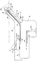
- Eine Ausführungsform der Erfindung wird nachstehend anhand der einzigen Zeichnung beschrieben, die eine Prinzipdarstellung der Vorrichtung zeigt.
- Die Vorrichtung 1 ist unterhalb einer Karosserie 2 eines Kraftfahrzeuges befestigt. Die Vorrichtung 1 besteht aus einem Kraftstoffbehälter 3, einem an der Oberseite 4 des Kraftstoffbehälters 3 angeordneten Ausgleichsbehälter 5 für den Kraftstoff und aus mindestens einer Betriebs-Entlüftungsleitung 6 und einer Betankungs-Entlüftungsleitung 14. An der Oberseite 7 des Ausgleichsbehälters 5 ist ein Anschluß 8 zur Atmosphäre oder zur Umgebung angeordnet.
- Der Kraftstoffbehälter 3 weist ein Einfüllrohr 9 mit einem Einfüllstutzen 10 auf. Der Einfüllstutzen 10 ist durch einen Verschluß oder Tankdeckel 11 in der gezeigten Darstellung verschlossen. Unterhalb des Tankdeckels 11 ist am Einfüllstutzen 10 ein Doppelanschluß 12 mit einer Öffnung zum Einfüllstutzen 10 hin ausgebildet.
- Am Doppelanschluß 12 ist das obere Ende der Betankungs-Entlüftungsleitung 14 angeschlossen. Die Betankungs-Entlüftungsleitung 14 führt nach unten zu einem an der Oberseite 4 des Kraftstoffbehälters 3 ausgebildeten Anschluß 16. An das obere Ende 15 des Doppelanschlusses 12 ist die Betriebs-Entlüftungsleitung 6 mit ihrem einen Ende 17 angeschlossen.
- Die Betriebs-Entlüftungsleitung 6 geht über das maximale Befüllniveau 13 hinaus und weist einen Wendepunkt 18 auf, der in der vorliegenden Ausführungsform an der höchsten Stelle der Betriebs-Entlüftungsleitung 6 in einer U-förmigen Schleife 19 liegt. Die Betriebs-Entlüftungsleitung 6 verläuft nach dem Wendepunkt 18 nach unten in Richtung der Oberseite 4 des Kraftstoffbehälters 3. An der tiefsten Stelle 20 eines Bodens 21 des Ausgleichsbehälters 5 ist das andere untere Ende 22 der Betriebs-Entlüftungsleitung 6 angeschlossen.
- Sind mehrere Betriebs-Entlüftungsleitungen vorgesehen, dann werden diese Betriebs-Entlüftungsleitungen 6 jeweils über das maximale Befüllniveau beispielsweise in der Form einer Schleife hochgeführt, so daß der Wendepunkt dieser Schleife oberhalb des maximalen Befüllniveaus 13 liegt. Das untere Ende der jeweiligen zusätzlichen Betriebs-Entlüftungsleitung ist auf dem gleichen tiefsten Niveau 20 am Boden 21 des Ausgleichsbehälters 5 luftdicht angeschlossen.
- Beim Fahrbetrieb fördert eine Kraftstoffpumpe 23 Kraftstoff aus dem Kraftstoffbehälter 3 zu einem nicht abgebildeten Verbrennungsmotor über eine Kraftstoffvorlaufleitung 24. Der zuviel zum Verbrennungsmotor geförderte Kraftstoff fließt über eine Kraftstoffrücklaufleitung 25 in den Kraftstoffbehälter 3 zurück.
Claims (6)
- Vorrichtung zum Entlüften eines Kraftstoffbehälters eines Kraftfahrzeuges, wobei der Kraftstoffbehälter über mindestens eine Betriebsentlüftungsleitung mit einem Ausgleichsbehälter verbunden ist,
dadurch gekennzeichnet, daß der Ausgleichsbehälter (5) unterhalb eines maximalen Befüllniveaus (13) angeordnet ist, daß mindestens eine Betriebs-Entlüftungsleitung (6) von der Oberseite (4) des Kraftstoffbehälters (3) über das maximale Befüllniveau (13) geführt ist und daß ein unteres Ende (22) der jeweiligen Betriebs-Entlüftungsleitung (6) an der tiefsten Stelle (20) eines Bodens (21) des Ausgleichsbehälters (5) angeschlossen ist. - Vorrichtung nach Anspruch 1,
dadurch gekennzeichnet, daß die vorhandenen Betriebs-Entlüftungsleitungen (6) an der tiefsten Stelle (20) des Bodens (21) des Ausgleichsbehälters (5) angeschlossen sind. - Vorrichtung nach den Ansprüchen 1 oder 2,
dadurch gekennzeichnet, daß ein Befüllen des Ausgleichsbehälters (5) durch eine Ausdehnung des Kraftstoffes im Kraftstoffbehälter (3) bei Wärmeeinwirkung über die vorhandene Anzahl der Betriebs-Entlüftungsleitungen (6) erfolgt. - Vorrichtung nach Anspruch 3,
dadurch gekennzeichnet, daß der Ausgleichsbehälter (5) über die Betankungs-Entlüftungsleitung (14) und eine daran angeschlossene Betriebs-Entlüftungsleitung (6) befüllbar ist. - Vorrichtung nach einem oder mehreren der vorhergehenden Ansprüche,
dadurch gekennzeichnet, daß eine Entleerung des Ausgleichsbehälters (5) aufgrund eines Unterdruckes im Kraftstoffbehälter (3) erfolgt, der bei der Kraftstoffentnahme über die Kraftstoffpumpe (23) aus dem Kraftstoffbehälter (3) während des Betriebes eines Verbrennungsmotores aufgebaut wird. - Vorrichtung nach einem oder mehreren der vorhergehenden Ansprüche,
dadurch gekennzeichnet, daß ein Anschluß (8) mittelbar oder unmittelbar zur Atmosphäre an der Oberseite (7) des Ausgleichsbehälters (5) angeordnet ist.
Applications Claiming Priority (2)
| Application Number | Priority Date | Filing Date | Title |
|---|---|---|---|
| DE19533919A DE19533919C2 (de) | 1995-09-13 | 1995-09-13 | Vorrichtung zum Entlüften eines Kraftstoffbehälters eines Kraftfahrzeuges |
| DE19533919 | 1995-09-13 |
Publications (3)
| Publication Number | Publication Date |
|---|---|
| EP0763441A2 true EP0763441A2 (de) | 1997-03-19 |
| EP0763441A3 EP0763441A3 (de) | 1998-04-15 |
| EP0763441B1 EP0763441B1 (de) | 1999-10-13 |
Family
ID=7772055
Family Applications (1)
| Application Number | Title | Priority Date | Filing Date |
|---|---|---|---|
| EP96109761A Expired - Lifetime EP0763441B1 (de) | 1995-09-13 | 1996-06-18 | Vorrichtung zum Entlüften eines Kraftstoffbehälters eines Kraftfahrzeuges |
Country Status (3)
| Country | Link |
|---|---|
| EP (1) | EP0763441B1 (de) |
| DE (2) | DE19533919C2 (de) |
| ES (1) | ES2137589T3 (de) |
Cited By (1)
| Publication number | Priority date | Publication date | Assignee | Title |
|---|---|---|---|---|
| WO2001038118A1 (de) * | 1999-11-26 | 2001-05-31 | Bayerische Motoren Werke Aktiengesellschaft | Ventil und ein mit einem ventil versehener kraftstoffbehälter eines kraftfahrzeuges |
Families Citing this family (1)
| Publication number | Priority date | Publication date | Assignee | Title |
|---|---|---|---|---|
| DE102005043744A1 (de) * | 2005-09-14 | 2007-03-22 | GM Global Technology Operations, Inc., Detroit | Entlüftungssystem für einen Kraftstoffbehälter |
Family Cites Families (8)
| Publication number | Priority date | Publication date | Assignee | Title |
|---|---|---|---|---|
| FR2164969A5 (de) * | 1971-12-13 | 1973-08-03 | Peugeot & Renault | |
| GB2168331A (en) * | 1984-12-12 | 1986-06-18 | Ford Motor Co | Vehicle fuel tank venting system |
| FR2583353B1 (fr) * | 1985-06-14 | 1987-07-24 | Renault | Reservoir a carburant en matiere synthetique, notamment pour vehicule automobile |
| DE4107184C1 (de) * | 1991-03-06 | 1992-05-27 | Mercedes-Benz Aktiengesellschaft, 7000 Stuttgart, De | |
| DE4121324C2 (de) * | 1991-06-27 | 1995-04-06 | Bayerische Motoren Werke Ag | Kraftstoffbehälter für ein Kraftfahrzeug |
| DE4121321A1 (de) * | 1991-06-27 | 1993-01-07 | Bayerische Motoren Werke Ag | Kraftstoffbehaelter fuer ein kraftfahrzeug |
| DE4121323C2 (de) * | 1991-06-27 | 1996-03-14 | Bayerische Motoren Werke Ag | Kraftstoffbehälter für ein Kraftfahrzeug |
| JP2549248Y2 (ja) * | 1991-08-30 | 1997-09-30 | 富士重工業株式会社 | 車両用燃料供給装置の安全回路 |
-
1995
- 1995-09-13 DE DE19533919A patent/DE19533919C2/de not_active Expired - Fee Related
-
1996
- 1996-06-18 ES ES96109761T patent/ES2137589T3/es not_active Expired - Lifetime
- 1996-06-18 EP EP96109761A patent/EP0763441B1/de not_active Expired - Lifetime
- 1996-06-18 DE DE59603340T patent/DE59603340D1/de not_active Expired - Fee Related
Cited By (2)
| Publication number | Priority date | Publication date | Assignee | Title |
|---|---|---|---|---|
| WO2001038118A1 (de) * | 1999-11-26 | 2001-05-31 | Bayerische Motoren Werke Aktiengesellschaft | Ventil und ein mit einem ventil versehener kraftstoffbehälter eines kraftfahrzeuges |
| US6581621B1 (en) | 1999-11-26 | 2003-06-24 | Bayerische Motoren Werke Aktiengesellschaft | Valve and fuel tank provided with a valve for a motor vehicle |
Also Published As
| Publication number | Publication date |
|---|---|
| DE59603340D1 (de) | 1999-11-18 |
| ES2137589T3 (es) | 1999-12-16 |
| EP0763441A3 (de) | 1998-04-15 |
| EP0763441B1 (de) | 1999-10-13 |
| DE19533919C2 (de) | 2000-02-17 |
| DE19533919A1 (de) | 1997-03-20 |
Similar Documents
| Publication | Publication Date | Title |
|---|---|---|
| DE19932713C2 (de) | Kraftstoffbehälter | |
| DE19954541C2 (de) | Vorrichtung zum Be- und Entlüften eines Kraftstoffbehälters | |
| DE19510821C2 (de) | Kraftstoffbehälter für Fahrzeuge, insbesondere Kraftfahrzeuge | |
| WO2002087915A1 (de) | Kraftstoffbehälter | |
| DE102016110559B4 (de) | Kraftstofftankstruktur | |
| EP2103473B1 (de) | Belüftung für einen Reduktionsmittelbehälter | |
| DE1942963A1 (de) | Sicherheitsvorrichtung zur Be- und Entlueftung von geschlossenen Behaeltern | |
| DE102013013212A1 (de) | Universelles Abschaltventil | |
| DE10238237A1 (de) | Kammerentleerungseinrichtung | |
| EP1136299A2 (de) | Entlüftungseinrichtung für einen Kraftstoffbehälter | |
| DE19647957A1 (de) | Kraftstoffbehälter für Kraftfahrzeuge | |
| DE3224943C2 (de) | Kraftstoffbehälteranlage für Kraftfahrzeuge, insbesondere Omnibusse | |
| EP0763441B1 (de) | Vorrichtung zum Entlüften eines Kraftstoffbehälters eines Kraftfahrzeuges | |
| DE2406843C3 (de) | Druckausgleichsanordnung für einen Fahrzeug-Kraftstoffbehälter | |
| EP0502326B1 (de) | Auslaufsperre als Teil einer Entlüftungsvorrichtung für Kraftstoffbehälter | |
| EP0011247B1 (de) | Vorrichtung zur Entlüftung von Kraftstoffbehältern bei Kraftfahrzeugen | |
| DE69603917T2 (de) | Verbesserte Kraftstoffzufuhr-Einrichtung in einem Fahrzeugtank | |
| DE2101826A1 (de) | Vorrichtung zur Ausluftung eines Kraftstoffbehälters insbesondere für Kraftfahrzeuge | |
| DE102005043745A1 (de) | Entlüftungssystem mit Siphonentleerung | |
| EP1154909B1 (de) | Ventil und ein mit einem ventil versehener kraftstoffbehälter eines kraftfahrzeuges | |
| DE102016124356A1 (de) | Vorrichtung und Verfahren zum Verhindern des Überlaufens von Kraftstoff aus einem Fahrzeugkraftstofftank | |
| EP3345780B1 (de) | Kraftstofftankvorrichtung | |
| DE102009022587A1 (de) | Entlüftungssystem für einen Kraftstoffbehälter eines Kraftfahrzeuges | |
| DE3312819C2 (de) | Kraftstoffbehälter für Kraftfahrzeuge | |
| DE102006056707B4 (de) | Reduktionsmittelbehälter und Reduktionsmittelanordnung zum Einfüllen und/oder Nachfüllen von Reduktionsmittel |
Legal Events
| Date | Code | Title | Description |
|---|---|---|---|
| PUAI | Public reference made under article 153(3) epc to a published international application that has entered the european phase |
Free format text: ORIGINAL CODE: 0009012 |
|
| AK | Designated contracting states |
Kind code of ref document: A2 Designated state(s): DE ES FR GB IT |
|
| PUAL | Search report despatched |
Free format text: ORIGINAL CODE: 0009013 |
|
| AK | Designated contracting states |
Kind code of ref document: A3 Designated state(s): DE ES FR GB IT |
|
| 17P | Request for examination filed |
Effective date: 19980515 |
|
| 17Q | First examination report despatched |
Effective date: 19980703 |
|
| GRAG | Despatch of communication of intention to grant |
Free format text: ORIGINAL CODE: EPIDOS AGRA |
|
| GRAG | Despatch of communication of intention to grant |
Free format text: ORIGINAL CODE: EPIDOS AGRA |
|
| GRAH | Despatch of communication of intention to grant a patent |
Free format text: ORIGINAL CODE: EPIDOS IGRA |
|
| GRAH | Despatch of communication of intention to grant a patent |
Free format text: ORIGINAL CODE: EPIDOS IGRA |
|
| GRAA | (expected) grant |
Free format text: ORIGINAL CODE: 0009210 |
|
| AK | Designated contracting states |
Kind code of ref document: B1 Designated state(s): DE ES FR GB IT |
|
| GBT | Gb: translation of ep patent filed (gb section 77(6)(a)/1977) |
Effective date: 19991014 |
|
| REF | Corresponds to: |
Ref document number: 59603340 Country of ref document: DE Date of ref document: 19991118 |
|
| REG | Reference to a national code |
Ref country code: ES Ref legal event code: FG2A Ref document number: 2137589 Country of ref document: ES Kind code of ref document: T3 |
|
| ET | Fr: translation filed | ||
| ITF | It: translation for a ep patent filed | ||
| PLBE | No opposition filed within time limit |
Free format text: ORIGINAL CODE: 0009261 |
|
| STAA | Information on the status of an ep patent application or granted ep patent |
Free format text: STATUS: NO OPPOSITION FILED WITHIN TIME LIMIT |
|
| 26N | No opposition filed | ||
| REG | Reference to a national code |
Ref country code: GB Ref legal event code: IF02 |
|
| PGFP | Annual fee paid to national office [announced via postgrant information from national office to epo] |
Ref country code: ES Payment date: 20030530 Year of fee payment: 8 |
|
| PGFP | Annual fee paid to national office [announced via postgrant information from national office to epo] |
Ref country code: GB Payment date: 20030612 Year of fee payment: 8 |
|
| PGFP | Annual fee paid to national office [announced via postgrant information from national office to epo] |
Ref country code: FR Payment date: 20030627 Year of fee payment: 8 |
|
| PGFP | Annual fee paid to national office [announced via postgrant information from national office to epo] |
Ref country code: DE Payment date: 20030721 Year of fee payment: 8 |
|
| PG25 | Lapsed in a contracting state [announced via postgrant information from national office to epo] |
Ref country code: GB Free format text: LAPSE BECAUSE OF NON-PAYMENT OF DUE FEES Effective date: 20040618 |
|
| PG25 | Lapsed in a contracting state [announced via postgrant information from national office to epo] |
Ref country code: ES Free format text: LAPSE BECAUSE OF NON-PAYMENT OF DUE FEES Effective date: 20040619 |
|
| PG25 | Lapsed in a contracting state [announced via postgrant information from national office to epo] |
Ref country code: DE Free format text: LAPSE BECAUSE OF NON-PAYMENT OF DUE FEES Effective date: 20050101 |
|
| GBPC | Gb: european patent ceased through non-payment of renewal fee |
Effective date: 20040618 |
|
| PG25 | Lapsed in a contracting state [announced via postgrant information from national office to epo] |
Ref country code: FR Free format text: LAPSE BECAUSE OF NON-PAYMENT OF DUE FEES Effective date: 20050228 |
|
| REG | Reference to a national code |
Ref country code: FR Ref legal event code: ST |
|
| PG25 | Lapsed in a contracting state [announced via postgrant information from national office to epo] |
Ref country code: IT Free format text: LAPSE BECAUSE OF NON-PAYMENT OF DUE FEES Effective date: 20050618 |
|
| REG | Reference to a national code |
Ref country code: ES Ref legal event code: FD2A Effective date: 20040619 |