EP0763394B1 - Shaping machine capable of suppressing tilt between work and tool - Google Patents
Shaping machine capable of suppressing tilt between work and tool Download PDFInfo
- Publication number
- EP0763394B1 EP0763394B1 EP96114625A EP96114625A EP0763394B1 EP 0763394 B1 EP0763394 B1 EP 0763394B1 EP 96114625 A EP96114625 A EP 96114625A EP 96114625 A EP96114625 A EP 96114625A EP 0763394 B1 EP0763394 B1 EP 0763394B1
- Authority
- EP
- European Patent Office
- Prior art keywords
- rod
- work
- tool
- broach cutter
- pipe
- Prior art date
- Legal status (The legal status is an assumption and is not a legal conclusion. Google has not performed a legal analysis and makes no representation as to the accuracy of the status listed.)
- Expired - Lifetime
Links
Images

Classifications
-
- B—PERFORMING OPERATIONS; TRANSPORTING
- B23—MACHINE TOOLS; METAL-WORKING NOT OTHERWISE PROVIDED FOR
- B23D—PLANING; SLOTTING; SHEARING; BROACHING; SAWING; FILING; SCRAPING; LIKE OPERATIONS FOR WORKING METAL BY REMOVING MATERIAL, NOT OTHERWISE PROVIDED FOR
- B23D37/00—Broaching machines or broaching devices
- B23D37/08—Broaching machines with vertically-arranged working tools
- B23D37/10—Broaching machines with vertically-arranged working tools for broaching inner surfaces
-
- Y—GENERAL TAGGING OF NEW TECHNOLOGICAL DEVELOPMENTS; GENERAL TAGGING OF CROSS-SECTIONAL TECHNOLOGIES SPANNING OVER SEVERAL SECTIONS OF THE IPC; TECHNICAL SUBJECTS COVERED BY FORMER USPC CROSS-REFERENCE ART COLLECTIONS [XRACs] AND DIGESTS
- Y10—TECHNICAL SUBJECTS COVERED BY FORMER USPC
- Y10T—TECHNICAL SUBJECTS COVERED BY FORMER US CLASSIFICATION
- Y10T409/00—Gear cutting, milling, or planing
- Y10T409/40—Broaching
- Y10T409/40455—Broaching with means to advance, infeed, or manipulate work
- Y10T409/4056—Broaching with means to advance, infeed, or manipulate work to infeed work past cutter
-
- Y—GENERAL TAGGING OF NEW TECHNOLOGICAL DEVELOPMENTS; GENERAL TAGGING OF CROSS-SECTIONAL TECHNOLOGIES SPANNING OVER SEVERAL SECTIONS OF THE IPC; TECHNICAL SUBJECTS COVERED BY FORMER USPC CROSS-REFERENCE ART COLLECTIONS [XRACs] AND DIGESTS
- Y10—TECHNICAL SUBJECTS COVERED BY FORMER USPC
- Y10T—TECHNICAL SUBJECTS COVERED BY FORMER US CLASSIFICATION
- Y10T409/00—Gear cutting, milling, or planing
- Y10T409/40—Broaching
- Y10T409/406475—Cutter infeed means
- Y10T409/40665—Imparting rectilinear motion to cutter
- Y10T409/407—Fluid powered means
Definitions
- This invention relates to broaching machines or like shaping machines for shaping a work into a predetermined shape by causing relative movements of the work and a tool.
- the invention concerns a shaping machine in which either a work or a tool is a rod-like member extending along a straight center line while the other is a member having a hole capable of being fitted on the rod-like member.
- the shaping machine By the shaping machine, the work is shaped into a predetermined shape while the member having the hole passes through the rod-like member from one end toward the other end of the rod-like member.
- a shaping machine is a broaching machine in which a surface of a hole of a nut-like work is finished while the nut-like work passes through a rod-like broach cutter from one end toward the other end.
- FIG. 2 is a front view showing the shaping machine.
- the illustrated shaping machine 1 is a vertical broaching machine for cutting a helical groove in an inner surface of a nut-like work w having a central through hole.
- the machine has two helical broaches 4 mounted in a column 2 by a drive mechanism 6 and support mechanisms 7.
- the column 2 has opposite side guides 9.
- a table 8 for supporting works w is vertically movable along the guides 9.
- the table 8 is driven by a table drive 3 which comprises a rack and pinion mechanism (not shown). Rising of the table 8 causes a lead bar 5 to be rotated by thread means, and the torque of the lead bar 5 is transmitted through the drive mechanism 6 to the two helical broaches 4.
- the two works w are processed by the respective helical broaches 4 to form helical grooves in their inner surfaces.
- the nut-like work w is shaped while the work w passes through the helical broach 4 from the lower end toward the upper end.
- the lower end of the broach 4 it is required for the lower end of the broach 4 to be secured to and released from the support mechanism 7, so that a work w to be shaped can be set to the lower end of the broach 4.
- the upper end of the broach 4 it is required for the upper end of the broach 4 to be secured to and released from the drive mechanism 6 so that the finished work w can be removed from the upper end of the broach 4.
- the rack and pinion mechanism Since it is very difficult to arrange the rack and pinion mechanism for raising and lowering the table 8 and the helical broach 4 in a co-axial relation, with a mechanism for securing and releasing the lower and upper ends of the broach 4 to and from the support mechanism 7 and drive mechanism 6 being provided in the machine, the rack and pinion mechanism is arranged on the table 8 at a place different from the place where the work w and the broach 4 are located.
- a center line of the rack and pinion mechanism for raising and lowering the work support table 8 is not coincident with but is off-set from the axis (i.e., center line) of each helical broach 4. Therefore, resistance caused by the helical broach 4 against the work w during the shaping process and raising force provided by the rack and pinion mechanism tend to cause the work w to be rotated vertically, thus generating a tilt of the work w with respect to the broach 4. This results in lower finishing accuracy.
- An object of the invention is to provide a shaping machine for shaping a work into a predetermined shape while a member having a hole passes through a rod-like member from one end toward the other end of the rod-like member, which can suppress the work from being tilted while being shaped.
- Another object of the invention is to provide a more compact shaping machine having lower rigidity compared to the prior art.
- the work to be shaped according to one aspect of the invention has a through hole like a nut.
- the invention is effective when shaping the through hole surface with a rod-like tool such as a broach cutter.
- the work is shaped into a predetermined shape while the nut-like work passes through the rod-like tool from one end toward the other end of the tool.
- a mechanism for feeding the work along the rod-like tool from one end toward the other end of the tool is provided.
- such feed mechanism is provided at an off-set position from the center line of the rod-like tool in order to avoid interference between the rod-like tool and the feed mechanism or between the feed mechanism and the mechanism for securing and releasing the tool to and from a tool supporting member.
- the center line of the feed mechanism is coincident with the center line of the rod-like tool without interference between the feed mechanism and the tool and also without interference between the feed mechanism and the mechanism for securing and releasing the tool.
- the feed mechanism preferably includes a pipe which accommodates the rod-like tool.
- the tool accommodated in the pipe does not interfere with the feed mechanism, while the rod-like tool can be concentric with the feed mechanism.
- a rod may be inserted in the pipe to secure and release the rod-like tool to and from the tool supporting member.
- the invention can also be used to shape an outer periphery of a rod-like work by moving a shaping tool having a hole along the rod-like work from one end toward the other end of the work.
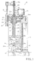
- a shaping machine according to an embodiment of the invention will now be described with reference to FIG. 1.
- the shaping machine according to this embodiment is a vertical broaching machine 10 for broaching an inner surface ws of a through hole wa in a work w.
- the machine has a column 12 extending upright from a bed 11.
- the column 12 has a sectional profile of an inverted L-shaped configuration.
- a nut 22 is mounted vertically on the horizontal top portion of the column 12.
- the nut 22 has a cylindrical portion 22t with a female thread 22n formed therein and a flange-like gear portion 22w atop the cylindrical portion 22t.
- the cylindrical portion 22t is mounted in bearings 12b such that it is rotatable about its axis relative to the column 12 but is axially immovable.
- a feed motor 24 is secured downward to the top of the column 12, and is secured to a feed gear 24w which engages the gear portion 22w of the nut 22.
- the nut 22 thus can be rotated by a predetermined angle about its axis by operating the feed motor 24.
- a pipe-like screw 26 having a feed screw formed in the outer periphery is screwed in the female thread 22n of the nut 22, and on the lower end of the pipe-like screw 26 is mounted a work holder 28 which can hold a work w.
- the work holder 28 is a box-like member having a ceiling 28u and a bottom 28d, which have an upper through hole 28a and a lower through hole 28b, respectively, these holes 28a and 28b being coaxial with the extension of an axis of a through hole 26k of the pipe-like screw 26.
- the work w is set on top of the bottom 28d such that it is concentric with the lower through hole 28b.
- Slide members 28s are secured to an upper portion and a lower portion of the work holder 28 on one side thereof, and are slidably engaged with a vertical guide 12y mounted on the column 12.
- the pipe-like screw 26 and the work holder 28 are thus incapable of being rotated, but they can be raised and lowered by screw action with rotation of the nut 22.
- a lift cylinder 30 is secured to the top portion of the column 12 on the side thereof opposite the feed motor 24, and has a piston rod 32 on which a stem portion of a horizontal support 33 is mounted.
- the horizontal support 33 has a free end on which a rod-like tool lift holder 35 is mounted coaxially with the pipe-like screw 26.
- the tool lift holder 35 is inserted in the pipe-like screw 26, and extends through the through hole 26k of the pipe 26.
- the tool lift holder 35 is inserted in the thorough hole 26k while holding an upper end of a broach cutter 14, and has a pipe-like case portion 35c.
- the case portion 35c has a chuck 35t mounted on its free end (i.e., lower end) and a chuck cylinder 35y mounted on its upper end.
- the case portion 35c further accommodates a transmission rod 35r for transmitting the movement of the chuck cylinder 35y to the chuck 35t.
- the tool lift holder 35 holding the upper end of the broach cutter 14 is raised or lowered through the pipe-like screw 26.
- the rod-like tool lift holder 35 is secured to or released from the upper end of the broach cutter 14.
- the broach cutter 14 is a rod-like cutting tool.
- a tool holder 40 is secured to the top of the bed 11 such as to releasably position the lower end of the broach cutter 14.
- a tool cotter 42 is horizontally mounted in a lower portion of the column 12 such as to secure the lower end of the broach cutter 14 positioned by the tool holder 40, with respect to the tool holder 40.
- the tool cotter 42 has a horizontal movable member 42m. The lower end of the broach cutter 14 is secured to the tool holder 40 by extending the movable member 42m horizontally into engagement with the tool holder 40 and also with the broach cutter 14.
- the lift cylinder 30 is operated to advance the piston rod 32 so as to bring the broach cutter 14 and the tool lift holder 35 to upper set positions thereof.
- the pipe-like screw 26 and the work holder 28 are held at their lower set positions.
- the lower end of the broach cutter 14 is separated from the tool holder 40 and the work w to be finished is set in the work holder 28 at a predetermined position thereof.
- the lift cylinder 30 is operated to retreat the piston rod 32, thus lowering the tool lift holder 35 and the broach cutter 14 through the pipe-like screw 26.
- the free lower end of the broach cutter 14 is passed through the upper through hole 28a of the work holder 28, then the through hole wa of the work w and then the lower through hole 28b of the work holder 28 and is inserted into the tool holder 40 (as shown by dashed lines in FIG. 1), so that the tool cotter 42 is operated to bring the movable member 42m thereof into engagement with the free lower end of the broach cutter 14.
- the free lower end of the broach cutter 14 is thus secured to the tool holder 40, and the work w to be finished is set to the lower end of the broach cutter 14. At this time, the other end of the broach cutter 14 is held secured to the tool lift holder 35.
- the feed motor 24 is operated to rotate the nut 22 via the feed gear 24w and the gear portion 22w.
- the rotation of the nut 22 causes the pipe-like screw 26 to be raised by the screw action, thus causing the work holder 28 secured to the pipe-like screw 26 to be raised along the guide 12y of the column 12.
- the work w set therein rises along and coaxially with the rod-like broach cutter 14, that is, the work w having the through hole wa proceeds along the rod-like broach cutter 14 from the lower end toward the other end (upper end).
- the inner surface ws of the through hole wa of the work w is finished by the broach cutter 14.
- the finishing process of the work w is completed when the top face of the pipe-like screw 26 is brought into contact with an upper portion of the tool lift holder 35 (i.e., the locality thereof supported by the horizontal support 33). At this time, the chuck 35t of the tool lift holder 35 is opened to release the tool lift holder 35 from the broach cutter 14.
- the lift cylinder 30 now can be moved by external forces. To take out the finished work w from the upper end of the broach cutter 14, the pipe-like screw 26, the work holder 28 and the work w are further raised, so that the tool lift holder 35 and the horizontal support 33 supporting the tool lift holder 35 are raised by the pipe-like screw 26.
- the feed motor 24 is operated reversely to cause reverse rotation of the nut 22, thus lowering the pipe-like screw 26 and the work holder 28 down to the initial positions (i.e., lower set positions) thereof.
- the lift cylinder 30 is operated to retreat the piston rod 32 so as to lower the tool lift holder 35 until the lower end of the tool lift holder 35 is in contact with the upper end of the broach cutter 14. The upper end of the broach cutter 14 is thus chucked again in the chuck 35t of the tool lift holder 35. Further, the movable member 42m of the tool cotter 42 is withdrawn from the tool holder 40 to release the lower end of the broach cutter.
- the lift cylinder 30 is operated again to advance the piston rod 32 from this state.
- the broach cutter 14 and the tool lift holder 35 are thus raised, so that the next work w can be set in the work holder 28 at a predetermined position thereof.
- the next work w is shaped or finished in the same way as the first work w.
- the pipe-like screw 26 and nut 22 constitute a feed mechanism according to the invention.
- the feed mechanism comprises the pipe-like screw 26 accommodating the rod-like broach cutter 14 and the tool lift holder 35.
- the center line of the pipe-like screw 26, etc. constituting the feed mechanism is not off-set from the axis (or center line) of the broach cutter 14.
- the resistance caused by the broach cutter 14 against the work during the shaping process and the raising force provided by the pipe-like screw 26 do not produce any moment tending to tilt the work w with respect to the broach cutter 14.
- the work w being worked thus is not tilted. It is thus possible to improve the finishing accuracy, reduce the rigidity of the work holder 28, guide 12y, column 12, etc. compared to that in the prior art, and reduce the cost of manufacture.
- a rod-like member 14, a feeding mechanism (nut 22 and screw 26) of a nut-like work w, means 40 for releasably securing the lower end of the rod-like member 14 and means 35 for releasably securing the upper end of the rod-like member 14 are arranged in a co-axial relation.
- the means 40 and the means 35 are capable of releasing the lower and upper ends, respectively.
- a cutting machine which comprises a feed mechanism including a pipe-like screw and a cutting tool movable therethrough.
- This structure does not require any cutting tool cover.
- the cutting tool and the feed screw can be set at the same position, it is possible to manufacture a compact cutting machine.
- the feed mechanism is constituted by the pipe-like screw 26, the nut 22, etc.
- a guide bar and an oil hydraulic cylinder or the like it is possible to utilize a rack and a pinion and a motor or the like. It is further possible to utilize a conical screw and a motor or the like.
- the broach cutter 14 is used as a rod-like tool, this is by no means limitative; it is possible to use a drill, a reamer, etc. as the rod-like tool.
- a rod-like tool is used, it is possible to utilize the invention for shaping the outer periphery of a rod-like work with a shaping tool having a hole.
- the distance required for the work to be moved may be made substantially equal to the length of the rod-like tool, thus permitting the reduction of the travel of the machine.
- the two ends of the rod-like member are alternately made to be free.
- the work which has been passed along the rod-like tool from one end toward the other end of the tool may be taken out of the tool without need of being returned to the afore-said one end. It is thus possible to form a complicated finished surface.
Description
- This invention relates to broaching machines or like shaping machines for shaping a work into a predetermined shape by causing relative movements of the work and a tool. Particularly, the invention concerns a shaping machine in which either a work or a tool is a rod-like member extending along a straight center line while the other is a member having a hole capable of being fitted on the rod-like member. By the shaping machine, the work is shaped into a predetermined shape while the member having the hole passes through the rod-like member from one end toward the other end of the rod-like member. One example of such a shaping machine is a broaching machine in which a surface of a hole of a nut-like work is finished while the nut-like work passes through a rod-like broach cutter from one end toward the other end.
- A prior art shaping machine pertaining to the invention is disclosed in Japanese Laid-Open Patent Publication No. 62-255011. FIG. 2 is a front view showing the shaping machine.
- The illustrated shaping machine 1 is a vertical broaching machine for cutting a helical groove in an inner surface of a nut-like work w having a central through hole. The machine has two
helical broaches 4 mounted in a column 2 by adrive mechanism 6 andsupport mechanisms 7. The column 2 hasopposite side guides 9. A table 8 for supporting works w is vertically movable along theguides 9. The table 8 is driven by a table drive 3 which comprises a rack and pinion mechanism (not shown). Rising of the table 8 causes alead bar 5 to be rotated by thread means, and the torque of thelead bar 5 is transmitted through thedrive mechanism 6 to the twohelical broaches 4. - While the table 8 is raised by a predetermined distance from its lower set position, the two works w are processed by the respective
helical broaches 4 to form helical grooves in their inner surfaces. - In this broaching machine 1, the nut-like work w is shaped while the work w passes through the
helical broach 4 from the lower end toward the upper end. In the machine, it is required for the lower end of thebroach 4 to be secured to and released from thesupport mechanism 7, so that a work w to be shaped can be set to the lower end of thebroach 4. Further, it is required for the upper end of thebroach 4 to be secured to and released from thedrive mechanism 6 so that the finished work w can be removed from the upper end of thebroach 4. - Since it is very difficult to arrange the rack and pinion mechanism for raising and lowering the table 8 and the
helical broach 4 in a co-axial relation, with a mechanism for securing and releasing the lower and upper ends of thebroach 4 to and from thesupport mechanism 7 anddrive mechanism 6 being provided in the machine, the rack and pinion mechanism is arranged on the table 8 at a place different from the place where the work w and thebroach 4 are located. - In this broaching machine 1, a center line of the rack and pinion mechanism for raising and lowering the work support table 8 is not coincident with but is off-set from the axis (i.e., center line) of each
helical broach 4. Therefore, resistance caused by thehelical broach 4 against the work w during the shaping process and raising force provided by the rack and pinion mechanism tend to cause the work w to be rotated vertically, thus generating a tilt of the work w with respect to thebroach 4. This results in lower finishing accuracy. - For suppressing the tilt of the work w with respect to the
broach 4, it is effective to increase the rigidity of theguides 9 of the column 2 and the table 8 or the like parts. Increasing the rigidity, however, results in an increase of the machine size. - An object of the invention is to provide a shaping machine for shaping a work into a predetermined shape while a member having a hole passes through a rod-like member from one end toward the other end of the rod-like member, which can suppress the work from being tilted while being shaped.
- Another object of the invention is to provide a more compact shaping machine having lower rigidity compared to the prior art.
- The work to be shaped according to one aspect of the invention has a through hole like a nut. The invention is effective when shaping the through hole surface with a rod-like tool such as a broach cutter. The work is shaped into a predetermined shape while the nut-like work passes through the rod-like tool from one end toward the other end of the tool.
- According to the aspect of the invention, a mechanism for feeding the work along the rod-like tool from one end toward the other end of the tool is provided. In a prior art shaping machine, such feed mechanism is provided at an off-set position from the center line of the rod-like tool in order to avoid interference between the rod-like tool and the feed mechanism or between the feed mechanism and the mechanism for securing and releasing the tool to and from a tool supporting member. According to the invention, the center line of the feed mechanism is coincident with the center line of the rod-like tool without interference between the feed mechanism and the tool and also without interference between the feed mechanism and the mechanism for securing and releasing the tool. Thus, according to the invention, no moment tending to tilt the work is generated between the work and the tool.
- The feed mechanism preferably includes a pipe which accommodates the rod-like tool. The tool accommodated in the pipe does not interfere with the feed mechanism, while the rod-like tool can be concentric with the feed mechanism. Moreover, a rod may be inserted in the pipe to secure and release the rod-like tool to and from the tool supporting member.
- The invention can also be used to shape an outer periphery of a rod-like work by moving a shaping tool having a hole along the rod-like work from one end toward the other end of the work.
- The invention will be more fully understood from the following detailed description and appended claims when taken along with the accompanying drawings.
-
- FIG. 1 is a fragmentary sectional view showing a broaching machine according to an embodiment of the invention; and
- FIG. 2 is a front view showing a prior art broaching machine.
-
- A shaping machine according to an embodiment of the invention will now be described with reference to FIG. 1.
- The shaping machine according to this embodiment is a
vertical broaching machine 10 for broaching an inner surface ws of a through hole wa in a work w. The machine has acolumn 12 extending upright from abed 11. Thecolumn 12 has a sectional profile of an inverted L-shaped configuration. Anut 22 is mounted vertically on the horizontal top portion of thecolumn 12. Thenut 22 has a cylindrical portion 22t with afemale thread 22n formed therein and a flange-like gear portion 22w atop the cylindrical portion 22t. The cylindrical portion 22t is mounted inbearings 12b such that it is rotatable about its axis relative to thecolumn 12 but is axially immovable. - A
feed motor 24 is secured downward to the top of thecolumn 12, and is secured to afeed gear 24w which engages thegear portion 22w of thenut 22. Thenut 22 thus can be rotated by a predetermined angle about its axis by operating thefeed motor 24. - A pipe-
like screw 26 having a feed screw formed in the outer periphery is screwed in thefemale thread 22n of thenut 22, and on the lower end of the pipe-like screw 26 is mounted awork holder 28 which can hold a work w. Thework holder 28 is a box-like member having aceiling 28u and abottom 28d, which have an upper throughhole 28a and a lower throughhole 28b, respectively, theseholes through hole 26k of the pipe-like screw 26. The work w is set on top of thebottom 28d such that it is concentric with the lower throughhole 28b. -
Slide members 28s are secured to an upper portion and a lower portion of thework holder 28 on one side thereof, and are slidably engaged with avertical guide 12y mounted on thecolumn 12. The pipe-like screw 26 and thework holder 28 are thus incapable of being rotated, but they can be raised and lowered by screw action with rotation of thenut 22. - A
lift cylinder 30 is secured to the top portion of thecolumn 12 on the side thereof opposite thefeed motor 24, and has apiston rod 32 on which a stem portion of ahorizontal support 33 is mounted. Thehorizontal support 33 has a free end on which a rod-liketool lift holder 35 is mounted coaxially with the pipe-like screw 26. Thetool lift holder 35 is inserted in the pipe-like screw 26, and extends through the throughhole 26k of thepipe 26. - The
tool lift holder 35 is inserted in thethorough hole 26k while holding an upper end of abroach cutter 14, and has a pipe-like case portion 35c. Thecase portion 35c has achuck 35t mounted on its free end (i.e., lower end) and achuck cylinder 35y mounted on its upper end. Thecase portion 35c further accommodates atransmission rod 35r for transmitting the movement of thechuck cylinder 35y to thechuck 35t. - With the above construction, by operating the
lift cylinder 30, thetool lift holder 35 holding the upper end of thebroach cutter 14 is raised or lowered through the pipe-like screw 26. With movement of thechuck cylinder 35y, the rod-liketool lift holder 35 is secured to or released from the upper end of thebroach cutter 14. Thebroach cutter 14 is a rod-like cutting tool. - Right underneath the lower through
hole 28b of thework holder 28, atool holder 40 is secured to the top of thebed 11 such as to releasably position the lower end of thebroach cutter 14. Atool cotter 42 is horizontally mounted in a lower portion of thecolumn 12 such as to secure the lower end of thebroach cutter 14 positioned by thetool holder 40, with respect to thetool holder 40. Thetool cotter 42 has a horizontalmovable member 42m. The lower end of thebroach cutter 14 is secured to thetool holder 40 by extending themovable member 42m horizontally into engagement with thetool holder 40 and also with thebroach cutter 14. - The operation of the broaching
machine 10 according to this embodiment will now be described. - As shown in FIG. 1, first the upper end of the
broach cutter 14 is chucked in thechuck 35t of thetool lift holder 35, and then thelift cylinder 30 is operated to advance thepiston rod 32 so as to bring thebroach cutter 14 and thetool lift holder 35 to upper set positions thereof. At this time, the pipe-like screw 26 and thework holder 28 are held at their lower set positions. In this state, the lower end of thebroach cutter 14 is separated from thetool holder 40 and the work w to be finished is set in thework holder 28 at a predetermined position thereof. - Subsequently, the
lift cylinder 30 is operated to retreat thepiston rod 32, thus lowering thetool lift holder 35 and thebroach cutter 14 through the pipe-like screw 26. Thus, the free lower end of thebroach cutter 14 is passed through the upper throughhole 28a of thework holder 28, then the through hole wa of the work w and then the lower throughhole 28b of thework holder 28 and is inserted into the tool holder 40 (as shown by dashed lines in FIG. 1), so that thetool cotter 42 is operated to bring themovable member 42m thereof into engagement with the free lower end of thebroach cutter 14. The free lower end of thebroach cutter 14 is thus secured to thetool holder 40, and the work w to be finished is set to the lower end of thebroach cutter 14. At this time, the other end of thebroach cutter 14 is held secured to thetool lift holder 35. - When the preparations for the broaching operation thus have been completed, the
feed motor 24 is operated to rotate thenut 22 via thefeed gear 24w and thegear portion 22w. The rotation of thenut 22 causes the pipe-like screw 26 to be raised by the screw action, thus causing thework holder 28 secured to the pipe-like screw 26 to be raised along theguide 12y of thecolumn 12. With the rising of thework holder 28, the work w set therein rises along and coaxially with the rod-like broach cutter 14, that is, the work w having the through hole wa proceeds along the rod-like broach cutter 14 from the lower end toward the other end (upper end). During this time, the inner surface ws of the through hole wa of the work w is finished by thebroach cutter 14. - The finishing process of the work w is completed when the top face of the pipe-
like screw 26 is brought into contact with an upper portion of the tool lift holder 35 (i.e., the locality thereof supported by the horizontal support 33). At this time, thechuck 35t of thetool lift holder 35 is opened to release thetool lift holder 35 from thebroach cutter 14. Thelift cylinder 30 now can be moved by external forces. To take out the finished work w from the upper end of thebroach cutter 14, the pipe-like screw 26, thework holder 28 and the work w are further raised, so that thetool lift holder 35 and thehorizontal support 33 supporting thetool lift holder 35 are raised by the pipe-like screw 26. As a result, the upper end of thebroach cutter 14 is separated from the lower end of thetool lift holder 35. The work w is thus taken out from the upper end of thebroach cutter 14. After the pipe-like screw 26 and thework holder 28 have been brought to their upper set positions, the work w is removed from thework holder 28. - When the broaching of the first work w has been completed in the above way, the
feed motor 24 is operated reversely to cause reverse rotation of thenut 22, thus lowering the pipe-like screw 26 and thework holder 28 down to the initial positions (i.e., lower set positions) thereof. Also, thelift cylinder 30 is operated to retreat thepiston rod 32 so as to lower thetool lift holder 35 until the lower end of thetool lift holder 35 is in contact with the upper end of thebroach cutter 14. The upper end of thebroach cutter 14 is thus chucked again in thechuck 35t of thetool lift holder 35. Further, themovable member 42m of thetool cotter 42 is withdrawn from thetool holder 40 to release the lower end of the broach cutter. To set the next work w, thelift cylinder 30 is operated again to advance thepiston rod 32 from this state. As shown in FIG. 1, thebroach cutter 14 and thetool lift holder 35 are thus raised, so that the next work w can be set in thework holder 28 at a predetermined position thereof. The next work w is shaped or finished in the same way as the first work w. The pipe-like screw 26 andnut 22 constitute a feed mechanism according to the invention. In other words, the feed mechanism comprises the pipe-like screw 26 accommodating the rod-like broach cutter 14 and thetool lift holder 35. - As has been described, in the vertical broaching machine according to the invention, the center line of the pipe-
like screw 26, etc. constituting the feed mechanism is not off-set from the axis (or center line) of thebroach cutter 14. Thus, the resistance caused by thebroach cutter 14 against the work during the shaping process and the raising force provided by the pipe-like screw 26 do not produce any moment tending to tilt the work w with respect to thebroach cutter 14. The work w being worked thus is not tilted. It is thus possible to improve the finishing accuracy, reduce the rigidity of thework holder 28,guide 12y,column 12, etc. compared to that in the prior art, and reduce the cost of manufacture. - According to this embodiment, a rod-
like member 14, a feeding mechanism (nut 22 and screw 26) of a nut-like work w, means 40 for releasably securing the lower end of the rod-like member 14 and means 35 for releasably securing the upper end of the rod-like member 14 are arranged in a co-axial relation. The means 40 and themeans 35 are capable of releasing the lower and upper ends, respectively. - While a preferred embodiment of the invention has been described, the embodiment covers the following various technical matters in addition to those as set forth in the appended claims.
- A cutting machine which comprises a feed mechanism including a pipe-like screw and a cutting tool movable therethrough.
- This structure does not require any cutting tool cover. In addition, since the cutting tool and the feed screw can be set at the same position, it is possible to manufacture a compact cutting machine.
- While in the embodiment, the feed mechanism is constituted by the pipe-
like screw 26, thenut 22, etc., alternatively it is possible to utilize a guide bar and an oil hydraulic cylinder or the like. It is also possible to utilize a rack and a pinion and a motor or the like. It is further possible to utilize a conical screw and a motor or the like. - While in the embodiment, the
broach cutter 14 is used as a rod-like tool, this is by no means limitative; it is possible to use a drill, a reamer, etc. as the rod-like tool. While in the embodiment, a rod-like tool is used, it is possible to utilize the invention for shaping the outer periphery of a rod-like work with a shaping tool having a hole. With an arrangement that a nut-like work is moved along a rod-like tool held stationary from one end toward the other end of the tool as in the embodiment, the distance required for the work to be moved may be made substantially equal to the length of the rod-like tool, thus permitting the reduction of the travel of the machine. In the embodiment, the two ends of the rod-like member are alternately made to be free. Thus, the work which has been passed along the rod-like tool from one end toward the other end of the tool, may be taken out of the tool without need of being returned to the afore-said one end. It is thus possible to form a complicated finished surface. - While the invention has been described with reference to a preferred embodiment thereof, it is to be understood that modifications or variations may be easily made without departing from the scope of the invention which is defined by the appended claims.
Claims (10)
- Shaping machine (10) wherein either a work (W) or a tool (14) is a rod-like member extending along a straight center line while the other is a member having a hole capable of being fitted on the rod-like member, and wherein the work is shaped while the member having the hole passes through the rod-like member from one end toward the other end of the rod-like member, the machine comprises a feed mechanism (22, 26) for causing relative movement of the rod-like member and the member having the hole to each other along the center line of the rod-like member, a center line of the feed mechanism being coincident with the center line of the rod-like member.
- The shaping machine according to claim 1, further comprising means (35t) for releasably securing the rod-like member at its both ends, respectively, the feed mechanism including means for feeding the member having the hole along the rod-like member held stationary from said one end toward said other end of the rod-like member, the feeding means including a pipe (26) for accommodating the rod-like member.
- The shaping machine according to claim 2, wherein the pipe has a feed screw formed in the outer periphery.
- The shaping machine according to claim 2, further comprising a mechanism for securing and releasing the rod-like member to and from the securing means, the mechanism including a rod extending through a through hole of the pipe.
- A broaching machine comprising:an elongate broach cutter (14); anda feed mechanism for feeding a work (W) having a hole to be broached by the broach cutter, along the broach cutter such that the work passes through the broach cutter from one end toward the other end of the broach cutter;a center line of the feed mechanism being coincident with a center line of the broach cutter.
- The broaching machine according to claim 5, wherein the feed mechanism includes a pipe (26) for accommodating the broach cutter.
- The broaching machine according to claim 6, wherein the pipe has a feed screw formed in the outer periphery.
- The broaching machine according to claim 6, further comprising:means (35t) for releasably securing said one end of the broach cutter; anda mechanism for securing and releasing said one end of the broach cutter to and from the securing means by taking hold of the other end of the broach cutter;the securing and releasing mechanism including a rod (35r) extending through a through hole of the pipe;said other end of the broach cutter being capable of being secured to and released from one end of the rod.
- The broaching machine according to claim 8, further comprising a mechanism for moving the rod along the center line of the broach cutter.
- The broaching machine according to claim 5, wherein the broach cutter is a helical cutter.
Applications Claiming Priority (3)
| Application Number | Priority Date | Filing Date | Title |
|---|---|---|---|
| JP23552895 | 1995-09-13 | ||
| JP07235528A JP3081139B2 (en) | 1995-09-13 | 1995-09-13 | Cutting machine |
| JP235528/95 | 1995-09-13 |
Publications (2)
| Publication Number | Publication Date |
|---|---|
| EP0763394A1 EP0763394A1 (en) | 1997-03-19 |
| EP0763394B1 true EP0763394B1 (en) | 2001-05-02 |
Family
ID=16987315
Family Applications (1)
| Application Number | Title | Priority Date | Filing Date |
|---|---|---|---|
| EP96114625A Expired - Lifetime EP0763394B1 (en) | 1995-09-13 | 1996-09-12 | Shaping machine capable of suppressing tilt between work and tool |
Country Status (6)
| Country | Link |
|---|---|
| US (1) | US5755539A (en) |
| EP (1) | EP0763394B1 (en) |
| JP (1) | JP3081139B2 (en) |
| KR (1) | KR100211441B1 (en) |
| CN (1) | CN1059144C (en) |
| DE (1) | DE69612648T2 (en) |
Families Citing this family (20)
| Publication number | Priority date | Publication date | Assignee | Title |
|---|---|---|---|---|
| DE19624404C2 (en) * | 1996-06-19 | 2000-11-09 | Forst Maschf Oswald | Vertical broaching machine |
| DE29813875U1 (en) | 1998-08-03 | 1998-10-08 | Karl Klink Gmbh Werkzeug Und M | Vertical broaching machine |
| DE19924517A1 (en) * | 1999-05-28 | 2000-11-30 | Forst Maschf Oswald | Vertical internal broaching machine |
| DE19942163A1 (en) * | 1999-09-04 | 2001-03-08 | Forst Maschf Oswald | Vertical internal broaching machine |
| DE20104159U1 (en) * | 2001-03-09 | 2001-06-07 | Gierth Lothar | Vertical broaching machine |
| JP3692348B2 (en) * | 2001-12-26 | 2005-09-07 | 株式会社不二越 | NC helical broaching machine |
| JP4119771B2 (en) * | 2003-02-26 | 2008-07-16 | 株式会社不二越 | Internal broaching machine |
| US7657125B2 (en) * | 2004-08-02 | 2010-02-02 | Searete Llc | Time-lapsing data methods and systems |
| CN101376181B (en) * | 2008-09-19 | 2012-12-12 | 张家港国隆机电五金有限公司 | Installation structure of lock core slot-producing machine broaching tool |
| US8857128B2 (en) * | 2009-05-18 | 2014-10-14 | Apple Inc. | Reinforced device housing |
| US8408972B2 (en) * | 2010-01-25 | 2013-04-02 | Apple Inc. | Apparatus and method for intricate cuts |
| US8372495B2 (en) | 2010-05-26 | 2013-02-12 | Apple Inc. | Electronic device enclosure using sandwich construction |
| US9120272B2 (en) | 2010-07-22 | 2015-09-01 | Apple Inc. | Smooth composite structure |
| US9011623B2 (en) | 2011-03-03 | 2015-04-21 | Apple Inc. | Composite enclosure |
| CN102699419B (en) * | 2012-05-29 | 2014-04-30 | 尹时中 | Hard broaching finish machining process for surface of internal keyway and device |
| US10407955B2 (en) | 2013-03-13 | 2019-09-10 | Apple Inc. | Stiff fabric |
| CN204608330U (en) | 2013-12-20 | 2015-09-02 | 苹果公司 | Braided fiber band |
| KR101449492B1 (en) * | 2014-08-22 | 2014-10-13 | 한국브로치주식회사 | sealling type vertical broaching machine |
| US10864686B2 (en) | 2017-09-25 | 2020-12-15 | Apple Inc. | Continuous carbon fiber winding for thin structural ribs |
| CN112893991B (en) * | 2021-02-24 | 2024-02-23 | 南通市中吕齿轮有限公司 | Gear stay wire groove process |
Family Cites Families (17)
| Publication number | Priority date | Publication date | Assignee | Title |
|---|---|---|---|---|
| US262375A (en) * | 1882-08-08 | Machine for surfacing rolls | ||
| US1669402A (en) * | 1921-06-08 | 1928-05-08 | Sullivan Machinery Co | Broaching machine |
| US1434711A (en) * | 1921-06-08 | 1922-11-07 | Francis J Lapointe | Manually-operated broaching machine |
| US1463272A (en) * | 1921-08-12 | 1923-07-31 | Frederick H Ragan | Power press |
| US1823975A (en) * | 1922-03-17 | 1931-09-22 | Oilgear Co | Broaching machine |
| US1532107A (en) * | 1923-01-19 | 1925-03-31 | Oilgear Co | Broaching machine |
| US1936073A (en) * | 1930-03-05 | 1933-11-21 | George J Russell | Hydraulic apparatus for broaching |
| US2315476A (en) * | 1941-06-17 | 1943-03-30 | Leblond Mach Tool Co R K | Broaching machine |
| DE2842223A1 (en) * | 1978-09-28 | 1980-04-17 | Exnii Metallorezh Stankov | Vertical broaching machine for vehicle engine blocks - uses two actuators to drive broach, with piston rods guided by horizontal beam |
| JPS5854931B2 (en) * | 1979-09-04 | 1983-12-07 | トヨタ自動車株式会社 | broaching machine |
| SU1063550A1 (en) * | 1982-04-07 | 1983-12-30 | Ленинградское Электромашиностроительное Объединение "Электросила" Им.С.М.Кирова | Vertical broaching machine |
| JPS60141425A (en) * | 1983-12-27 | 1985-07-26 | Amada Co Ltd | Method of controlling cutting operation of broaching machine |
| JPS62255011A (en) * | 1986-04-28 | 1987-11-06 | Nachi Fujikoshi Corp | Helical broach machine |
| DE4235145A1 (en) * | 1992-10-19 | 1994-04-21 | Forst Maschf Oswald | Internal broaching machine, in particular vertical internal broaching machine |
| EP0606827A1 (en) * | 1993-01-12 | 1994-07-20 | OFFICINE MECCANICHE VARINELLI S.p.A. | Vertical internal push broaching machine |
| FR2711564B1 (en) * | 1993-10-29 | 1996-01-12 | Framatome Sa | Installation for broaching openings for crossing a plate and broaching method. |
| GB9418602D0 (en) * | 1994-09-15 | 1994-11-02 | Thomson Ibl Ltd | Broaching device |
-
1995
- 1995-09-13 JP JP07235528A patent/JP3081139B2/en not_active Expired - Lifetime
-
1996
- 1996-09-12 US US08/710,157 patent/US5755539A/en not_active Expired - Fee Related
- 1996-09-12 EP EP96114625A patent/EP0763394B1/en not_active Expired - Lifetime
- 1996-09-12 KR KR1019960039570A patent/KR100211441B1/en not_active IP Right Cessation
- 1996-09-12 DE DE69612648T patent/DE69612648T2/en not_active Expired - Fee Related
- 1996-09-13 CN CN96112933A patent/CN1059144C/en not_active Expired - Fee Related
Also Published As
| Publication number | Publication date |
|---|---|
| JP3081139B2 (en) | 2000-08-28 |
| CN1150074A (en) | 1997-05-21 |
| EP0763394A1 (en) | 1997-03-19 |
| US5755539A (en) | 1998-05-26 |
| JPH0976118A (en) | 1997-03-25 |
| DE69612648D1 (en) | 2001-06-07 |
| CN1059144C (en) | 2000-12-06 |
| KR100211441B1 (en) | 1999-08-02 |
| DE69612648T2 (en) | 2001-09-20 |
| KR970014891A (en) | 1997-04-28 |
Similar Documents
| Publication | Publication Date | Title |
|---|---|---|
| EP0763394B1 (en) | Shaping machine capable of suppressing tilt between work and tool | |
| DE2535135C2 (en) | ||
| US4090281A (en) | Machine tool with multiple tool turret | |
| DE3041171A1 (en) | NUMERICALLY CONTROLLED LATHE | |
| DE19918082A1 (en) | Universal machine tool | |
| US4141278A (en) | Polygonal turning machine | |
| DE3818903A1 (en) | DRILLING AND MILLING PLANT | |
| DE19504368A1 (en) | Machine tool with multi-station workholding spindles | |
| EP2021149B1 (en) | Machine tool | |
| EP0260692B1 (en) | Machine tool with a drilling and milling spindle carrier movable in the z direction on a machine body | |
| JPS5848285B2 (en) | Crankshaft processing equipment | |
| US3460412A (en) | Tool-changing devices for machine tools | |
| DE19855197A1 (en) | Program-controlled grinding machine | |
| DE1552355B1 (en) | Automatic turret lathe | |
| US5725418A (en) | Grinding unit | |
| DE3904299C1 (en) | Combined machine tool | |
| DE3717016C2 (en) | ||
| CN116900350B (en) | Automatic drilling equipment for mechanical manufacturing and using method thereof | |
| DE931209C (en) | Lathe with post-forming support | |
| JP2645777B2 (en) | Indexing device for exchangeable head machine tools | |
| SU1000177A1 (en) | Groove milling automatic machine | |
| SU1093399A2 (en) | Multiple-spindle vertical machine | |
| KR950008797B1 (en) | Machining center having tool magazine | |
| GB2184679A (en) | Lathe | |
| SU889294A1 (en) | Drilling machine |
Legal Events
| Date | Code | Title | Description |
|---|---|---|---|
| PUAI | Public reference made under article 153(3) epc to a published international application that has entered the european phase |
Free format text: ORIGINAL CODE: 0009012 |
|
| 17P | Request for examination filed |
Effective date: 19960912 |
|
| AK | Designated contracting states |
Kind code of ref document: A1 Designated state(s): DE FR GB |
|
| GRAG | Despatch of communication of intention to grant |
Free format text: ORIGINAL CODE: EPIDOS AGRA |
|
| 17Q | First examination report despatched |
Effective date: 20000725 |
|
| GRAG | Despatch of communication of intention to grant |
Free format text: ORIGINAL CODE: EPIDOS AGRA |
|
| GRAH | Despatch of communication of intention to grant a patent |
Free format text: ORIGINAL CODE: EPIDOS IGRA |
|
| GRAH | Despatch of communication of intention to grant a patent |
Free format text: ORIGINAL CODE: EPIDOS IGRA |
|
| GRAA | (expected) grant |
Free format text: ORIGINAL CODE: 0009210 |
|
| AK | Designated contracting states |
Kind code of ref document: B1 Designated state(s): DE FR GB |
|
| REF | Corresponds to: |
Ref document number: 69612648 Country of ref document: DE Date of ref document: 20010607 |
|
| ET | Fr: translation filed | ||
| REG | Reference to a national code |
Ref country code: GB Ref legal event code: IF02 |
|
| PLBE | No opposition filed within time limit |
Free format text: ORIGINAL CODE: 0009261 |
|
| STAA | Information on the status of an ep patent application or granted ep patent |
Free format text: STATUS: NO OPPOSITION FILED WITHIN TIME LIMIT |
|
| 26N | No opposition filed | ||
| REG | Reference to a national code |
Ref country code: GB Ref legal event code: 746 Effective date: 20060103 |
|
| PGFP | Annual fee paid to national office [announced via postgrant information from national office to epo] |
Ref country code: GB Payment date: 20060906 Year of fee payment: 11 |
|
| PGFP | Annual fee paid to national office [announced via postgrant information from national office to epo] |
Ref country code: DE Payment date: 20060907 Year of fee payment: 11 |
|
| PGFP | Annual fee paid to national office [announced via postgrant information from national office to epo] |
Ref country code: FR Payment date: 20060908 Year of fee payment: 11 |
|
| GBPC | Gb: european patent ceased through non-payment of renewal fee |
Effective date: 20070912 |
|
| PG25 | Lapsed in a contracting state [announced via postgrant information from national office to epo] |
Ref country code: DE Free format text: LAPSE BECAUSE OF NON-PAYMENT OF DUE FEES Effective date: 20080401 |
|
| REG | Reference to a national code |
Ref country code: FR Ref legal event code: ST Effective date: 20080531 |
|
| PG25 | Lapsed in a contracting state [announced via postgrant information from national office to epo] |
Ref country code: FR Free format text: LAPSE BECAUSE OF NON-PAYMENT OF DUE FEES Effective date: 20071001 |
|
| PG25 | Lapsed in a contracting state [announced via postgrant information from national office to epo] |
Ref country code: GB Free format text: LAPSE BECAUSE OF NON-PAYMENT OF DUE FEES Effective date: 20070912 |