EP0761992A1 - Gewindeformendes Verbindungselement - Google Patents
Gewindeformendes Verbindungselement Download PDFInfo
- Publication number
- EP0761992A1 EP0761992A1 EP96113599A EP96113599A EP0761992A1 EP 0761992 A1 EP0761992 A1 EP 0761992A1 EP 96113599 A EP96113599 A EP 96113599A EP 96113599 A EP96113599 A EP 96113599A EP 0761992 A1 EP0761992 A1 EP 0761992A1
- Authority
- EP
- European Patent Office
- Prior art keywords
- screw
- tip
- connecting element
- element according
- area
- Prior art date
- Legal status (The legal status is an assumption and is not a legal conclusion. Google has not performed a legal analysis and makes no representation as to the accuracy of the status listed.)
- Granted
Links
- 238000010079 rubber tapping Methods 0.000 title 1
- 230000002093 peripheral effect Effects 0.000 claims description 3
- 239000000463 material Substances 0.000 description 3
- 238000005553 drilling Methods 0.000 description 2
- 239000000835 fiber Substances 0.000 description 2
- 230000015572 biosynthetic process Effects 0.000 description 1
- 230000000694 effects Effects 0.000 description 1
- 238000007373 indentation Methods 0.000 description 1
- 239000011122 softwood Substances 0.000 description 1
Images

Classifications
-
- F—MECHANICAL ENGINEERING; LIGHTING; HEATING; WEAPONS; BLASTING
- F16—ENGINEERING ELEMENTS AND UNITS; GENERAL MEASURES FOR PRODUCING AND MAINTAINING EFFECTIVE FUNCTIONING OF MACHINES OR INSTALLATIONS; THERMAL INSULATION IN GENERAL
- F16B—DEVICES FOR FASTENING OR SECURING CONSTRUCTIONAL ELEMENTS OR MACHINE PARTS TOGETHER, e.g. NAILS, BOLTS, CIRCLIPS, CLAMPS, CLIPS OR WEDGES; JOINTS OR JOINTING
- F16B25/00—Screws that cut thread in the body into which they are screwed, e.g. wood screws
- F16B25/0036—Screws that cut thread in the body into which they are screwed, e.g. wood screws characterised by geometric details of the screw
- F16B25/0042—Screws that cut thread in the body into which they are screwed, e.g. wood screws characterised by geometric details of the screw characterised by the geometry of the thread, the thread being a ridge wrapped around the shaft of the screw
- F16B25/0052—Screws that cut thread in the body into which they are screwed, e.g. wood screws characterised by geometric details of the screw characterised by the geometry of the thread, the thread being a ridge wrapped around the shaft of the screw the ridge having indentations, notches or the like in order to improve the cutting behaviour
-
- F—MECHANICAL ENGINEERING; LIGHTING; HEATING; WEAPONS; BLASTING
- F16—ENGINEERING ELEMENTS AND UNITS; GENERAL MEASURES FOR PRODUCING AND MAINTAINING EFFECTIVE FUNCTIONING OF MACHINES OR INSTALLATIONS; THERMAL INSULATION IN GENERAL
- F16B—DEVICES FOR FASTENING OR SECURING CONSTRUCTIONAL ELEMENTS OR MACHINE PARTS TOGETHER, e.g. NAILS, BOLTS, CIRCLIPS, CLAMPS, CLIPS OR WEDGES; JOINTS OR JOINTING
- F16B25/00—Screws that cut thread in the body into which they are screwed, e.g. wood screws
- F16B25/001—Screws that cut thread in the body into which they are screwed, e.g. wood screws characterised by the material of the body into which the screw is screwed
- F16B25/0015—Screws that cut thread in the body into which they are screwed, e.g. wood screws characterised by the material of the body into which the screw is screwed the material being a soft organic material, e.g. wood or plastic
-
- F—MECHANICAL ENGINEERING; LIGHTING; HEATING; WEAPONS; BLASTING
- F16—ENGINEERING ELEMENTS AND UNITS; GENERAL MEASURES FOR PRODUCING AND MAINTAINING EFFECTIVE FUNCTIONING OF MACHINES OR INSTALLATIONS; THERMAL INSULATION IN GENERAL
- F16B—DEVICES FOR FASTENING OR SECURING CONSTRUCTIONAL ELEMENTS OR MACHINE PARTS TOGETHER, e.g. NAILS, BOLTS, CIRCLIPS, CLAMPS, CLIPS OR WEDGES; JOINTS OR JOINTING
- F16B25/00—Screws that cut thread in the body into which they are screwed, e.g. wood screws
- F16B25/0036—Screws that cut thread in the body into which they are screwed, e.g. wood screws characterised by geometric details of the screw
- F16B25/0084—Screws that cut thread in the body into which they are screwed, e.g. wood screws characterised by geometric details of the screw characterised by geometric details of the tip
Definitions
- the present invention relates to a thread-forming connecting element, in particular a screw with a single or multiple thread extending at least partially over its screw shaft, a screw tip and preferably a screw head, the thread extending to the tip of the screw tip.
- Such a screw is e.g. known from German patent application 33 35 092.2.
- This known screw has a reduced screwing-in torque due to the recesses interrupting the flank surface on the flank surface of the thread in the section of troughs of the undulating thread edge. This screw has proven itself very well in practice.
- the present invention has for its object to provide a thread-forming connecting element, in particular a self-drilling screw, in which the tightening torque has a flat (slight) increase at the beginning of screwing in, but the holding forces are not compared to known connecting elements, for example screws are reduced.
- this is achieved in that in the area of the connecting element or screw tip on its peripheral surface, at least one friction edge area extends in the element or screw longitudinal direction at least over a partial length of the element or screw tip.
- the screw according to the invention thus has a thread that extends through to the tip of the screw tip, as a result of which a gripping tip is formed, and a friction area. This friction area cuts the material fibers and the gripping tip grips immediately when screwed in, so that an axial force is created immediately.
- the screw according to the invention is particularly suitable for softwood.
- the friction area has such a slight cutting effect that the holding forces are not affected. Due to the special design according to the invention, the core diameter is not changed, which ensures that the holding forces are not reduced.
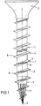
- a screw according to the invention consists of a screw shaft 1, a screw head 2 with a simple slot or cross recess or the like and a screw tip 3.
- the screw shaft 1 has the same diameter over its entire length, and the screw tip 3 tapers continuously from the screw shaft 1 to its tip 5.
- a screw thread 4 is formed on the screw shaft 1 and on the screw tip 3 and extends to the tip 5 of the screw tip 3.
- the edge 8 forming the thread burr of the threads 4 forming the thread runs in the illustrated embodiment in a wave shape, ie there is a continuous sequence of ridges (wave crests 6) and depressions (wave troughs 7), the thread outer diameter being determined by the distance of the thread edge 8 from the central axis the screw in the region of the wave crests 6 is determined.
- 7 depressions 9 are formed in each case in the region of the troughs in the advantageous embodiment shown on the flanks of the thread.
- the thread edge 8 in the area of the respective trough 7 forms the upper limit of the depressions 9.
- the depressions 9 are arranged in the area of the screw tip 3 and in the adjoining area of the screw shaft 1 over the pitch of two threads.
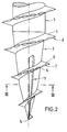
- At least one friction edge area 11 in the area of the screw tip 3 on its peripheral surface at least one friction edge area 11, see FIG. 2, extends substantially axially over a partial length of the screw tip 3.
- a multiplicity of friction edge regions 11 are designed to run alongside one another at uniform intervals on the circumference of the screw tip 3.
- Fig. 3 is one, seen circumferentially, immediate Lining up of rubbing edge regions 11 is present. It is also within the scope of the invention if the friction edge region (s) 11 also extend at least partially in the circumferential direction.
- the rubbing edge region 11 or the rubbing edge regions 11 is designed such that the largest diameter of the screw tip 3 in the section of the rubbing edge regions 11 is less than / equal to the core diameter of the screw shaft 1.
- the axial extent of the rubbing edge area 11 or the rubbing edge areas 11 corresponds minimally to a pitch of the screw thread and maximally to the length of the screw tip 3.
- the axial extent of the rubbing edge area 11 or the rubbing edge areas 11 corresponds to approximately two pitch heights.
- the friction edge region 11, viewed in cross section has the shape of a triangle.
- symmetrical or asymmetrical cross-sectional shapes can be provided.
- the rubbing edge region 11 is designed as a rib, the rib tip 12 forming the rubbing edge.
- the height of the ribs increases continuously in the direction of the screw head 2, starting from the tip 5.
- the rib height in the area of the tip 5 is zero and rises from there to such a height that at the end of the rib forming the friction edge area 11, the largest diameter of the screw tip 3 in the friction edge area 11 is less than / equal to the core diameter of the screw shaft 1.
- the screw tip 3 is designed as a tip with a stepped angle so that it in its area beginning at the tip 5, which has an axial extension of approximately one pitch, has a larger angle of inclination than in the area adjoining it to the end of the screw tip 3.
- the inventive design of the screw according to the invention designed as a self-drilling and thread-forming screw, with the thread running through to the tip 5 and with the formation of a friction edge region 11 in the area of the screw tip 3, achieves a flatter (lower) tightening torque without increasing the core diameter. This prevents the material from fanning out when screwing in, since the material fibers are cut by the friction cone.
- the thread edge 8 is smooth, i.e. is formed without a sequence of wave crests 6 and wave troughs 7.
- An embodiment is also possible, only a series of wave crests 6 and wave troughs 7 being present, without indentations 9 being present in the flank region of the thread.
- the screw thread can also be designed as a multi-start thread.
Landscapes
- Engineering & Computer Science (AREA)
- General Engineering & Computer Science (AREA)
- Mechanical Engineering (AREA)
- Geometry (AREA)
- Physics & Mathematics (AREA)
- Wood Science & Technology (AREA)
- Life Sciences & Earth Sciences (AREA)
- Dispersion Chemistry (AREA)
- Chemical & Material Sciences (AREA)
- Dowels (AREA)
- Connection Of Plates (AREA)
- Mutual Connection Of Rods And Tubes (AREA)
- Polishing Bodies And Polishing Tools (AREA)
- Artificial Filaments (AREA)
- Prostheses (AREA)
- Surgical Instruments (AREA)
- Materials For Medical Uses (AREA)
- External Artificial Organs (AREA)
Abstract
Description
- Die vorliegende Erfindung betrifft ein gewindeformendes Verbindungselement, insbesondere eine Schraube mit einem sich zumindest teilweise über ihren Schraubenschaft erstreckenden ein- oder mehrgängigen Gewinde, einer Schraubenspitze und vorzugsweise einem Schraubenkopf, wobei das Gewinde bis zur Spitze der Schraubenspitze verläuft.
- Eine derartige Schraube ist z.B. aus der deutschen Patentanmeldung 33 35 092.2 bekannt. Diese bekannte Schraube weist aufgrund der auf der Flankenfläche des Gewindeganges die Flankenfläche unterbrechenden Vertiefungen im Abschnitt von Wellentälern der wellenförmig verlaufenden Gewindekante ein reduziertes Eindrehmoment auf. Diese Schraube hat sich in der Praxis sehr gut bewährt.
- Der vorliegenden Erfindung liegt die Aufgabe zugrunde, ein gewindeformendes Verbindungselement, insbesondere eine selbstbohrende Schraube, zu schaffen, bei dem das Anzugsmoment zu Beginn des Einschraubens einen flachen (geringen) Anstieg aufweist, wobei aber die Haltekräfte im Vergleich zu bekannten Verbindungselementen, z.B. Schrauben, nicht verringert sind.
- Erfindungsgemäß wird dies dadurch erreicht, daß im Bereich der Verbindungselement- bzw. der Schraubenspitze an deren Umfangsfläche sich mindestens ein Reibkantenbereich in Element- bzw. Schraubenlängsrichtung zumindest über eine Teillänge der Element- bzw. Schraubenspitze erstreckt. Die erfindungsgemäße Schraube besitzt somit ein bis zur Spitze der Schraubenspitze durchgehendes Gewinde, wodurch eine Greifspitze ausgebildet wird, und einen Reibbereich. Dieser Reibbereich zerschneidet die Materialfasern und die Greifspitze faßt sofort beim Eindrehen an, so daß unmittelbar eine Axialkraft entsteht. Die erfindungsgemäße Schraube ist insbesondere für Weichholz geeignet. Der Reibbereich hat eine so geringfügige spanende Wirkung, daß die Haltekräfte nicht beeinträchtigt werden. Aufgrund der speziellen erfindungsgemäßen Ausgestaltung wird der Kerndurchmesser nicht verändert, wodurch gewährleistet ist, daß die Haltekräfte nicht gemindert werden.
- Vorteilhafte Ausführungen der Erfindung sind in den Unteransprüchen enthalten. Anhand der in den beiliegenden Zeichnungen dargestellten Ausführungsbeispiele wird die Erfindung näher erläutert. Es zeigen:
- Fig. 1
- eine Seitenansicht einer ersten Ausführungsform einer erfindungsgemäßen Schraube,
- Fig. 2
- eine Teilansicht eines zweiten Ausführungsbeispiels einer erfindungsgemäßen Schraube in Seitenansicht,
- Fig. 3
- einen Schnitt entlang der Schnittlinie III-III in Fig. 2.
- Wie sich aus Fig. 1 ergibt, besteht eine erfindungsgemäße Schraube aus einem Schraubenschaft 1, einem Schraubenkopf 2 mit einem einfachen Schlitz oder Kreuzschlitz oder dergleichen und einer Schraubenspitze 3. Der Schraubenschaft 1 weist über seine gesamte Länge einen gleichen Durchmesser auf, und die Schraubenspitze 3 verjüngt sich vom Schraubenschaft 1 kontinuierlich bis zu ihrer Spitze 5 hin. Am Schraubenschaft 1 und an der Schraubenspitze 3 ist ein Schraubgewinde 4 ausgebildet, das bis zur Spitze 5 der Schraubenspitze 3 verläuft. Die den Gewindegrat bildende Kante 8 der das Gewinde 4 bildenden Gewindegänge verläuft im dargestellten Ausführungsbeispiel wellenförmig, d.h. es ist eine stetige Folge von Erhöhungen (Wellenberge 6) und Vertiefungen (Wellentäler 7) vorhanden, wobei der Gewindeaußendurchmesser durch den Abstand der Gewindekante 8 von der Mittelachse der Schraube im Bereich der Wellenberge 6 bestimmt wird. Weiterhin sind im dargestellten vorteilhaften Ausführungsbeispiel auf den Flanken des Gewindeganges jeweils im Bereich der Wellentäler 7 Vertiefungen 9 ausgebildet. Hierbei bildet die Gewindekante 8 im Bereich des jeweiligen Wellentals 7 die Oberbegrenzung der Vertiefungen 9. Die Vertiefungen 9 sind im Bereich der Schraubenspitze 3 sowie im anschließenden Bereich des Schraubenschaftes 1 über die Ganghöhe von zwei Gewindegängen angeordnet. Weiterhin ist erfindungsgemäß vorgesehen, daß im Bereich der Schraubenspitze 3 an deren Umfangsfläche sich mindestens ein Reibkantenbereich 11, siehe Fig. 2, über eine Teillänge der Schraubenspitze 3 im wesentlichen axial erstreckt. Wie aus Fig. 1 zu erkennen ist, kann es zweckmäßig sein, wenn eine Vielzahl von Reibkantenbereichen 11 in gleichmäßigen Abständen auf dem Umfang der Schraubenspitze 3 verteilt nebeneinander verlaufend ausgebildet sind. In Fig. 3 ist eine, umfangsgemäß gesehen, unmittelbare Aneinanderreihung von Reibkantenbereichen 11 vorhanden. Es liegt ebenfalls im Rahmen der Erfindung, wenn der oder die Reibkantenbereich(e) 11 sich zumindest partiell auch in Umfangsrichtung erstrecken. Vorteilhafterweise ist der Reibkantenbereich 11 bzw. die Reibkantenbereiche 11 derart ausgebildet, daß der größte Durchmesser der Schraubenspitze 3 im Abschnitt der Reibkantenbereiche 11 kleiner/gleich dem Kerndurchmesser des Schraubenschaftes 1 ist. Die axiale Erstreckung des Reibkantenbereiches 11 bzw. der Reibkantenbereiche 11 entspricht von der Spitze 5 ausgehend minimal einer Ganghöhe des Schraubgewindes und maximal der Länge der Schraubenspitze 3. Im dargestellten Ausführungsbeispiel entspricht die axiale Erstreckung des Reibkantenbereiches 11 bzw. der Reibkantenbereiche 11 etwa zwei Ganghöhen. Wie insbesondere aus Fig. 3 zu erkennen ist, besitzt der Reibkantenbereich 11, im Querschnitt gesehen, die Form eines Dreiecks. Hierbei können symmetrische oder asymmetrische Querschnittsformen vorgesehen sein. Weiterhin ist zu erkennen, daß in den dargestellten Ausführungsbeispielen der Reibkantenbereich 11 als Rippe ausgebildet ist, wobei die Rippenspitze 12 die Reibkante bildet. Zudem ist es vorteilhaft, wenn sich die Rippenhöhe in Richtung auf den Schraubenkopf 2, ausgehend von der Spitze 5, kontinuierlich vergrößert. Hierbei sitzt die Rippenhöhe im Bereich der Spitze 5 den Betrag Null und steigt von dort zu einer derartigen Rippenhöhe an, daß am Ende der den Reibkantenbereich 11 bildenden Rippe der größte Durchmesser der Schraubenspitze 3 im Reibkantenbereich 11 kleiner/gleich dem Kerndurchmesser des Schraubenschaftes 1 ist.
- Weiterhin ist zu erkennen, daß im dargestellten vorteilhaften Ausführungsbeispiel die Schraubenspitze 3 als Spitze mit einem gestuften Winkel so ausgebildet ist, so daß sie in ihrem an der Spitze 5 beginnenden Bereich, der eine axiale Erstreckung von etwa einer Ganghöhe hat, einen größeren Neigungswinkel besitzt als in sich daran anschließenden Bereich bis zum Ende der Schraubenspitze 3.
- Durch die erfindungsgemäße Ausgestaltung der als selbstbohrende und gewindeformende Schraube ausgebildeten erfindungsgemäßen Schraube mit dem bis zur Spitze 5 durchlaufenden Gewinde und mit der Ausbildung eines Reibkantenbereichs 11 im Bereich der Schraubenspitze 3 wird ein flacheres (geringeres) Anzugsmoment erreicht, ohne daß der Kerndurchmesser vergrößert wird. Hierbei wird ein Aufspleißen des Materials beim Einschrauben vermieden, da durch den Reibkegel die Materialfasern zerschnitten werden.
- Es liegt im Rahmen der Erfindung, wenn die Gewindekante 8 glatt, d.h. ohne eine Folge von Wellenbergen 6 und Wellentälern 7, ausgebildet ist. Ebenfalls ist eine Ausführungsform möglich, wobei lediglich eine Folge von Wellenbergen 6 und Wellentälern 7 vorhanden ist, ohne, daß Vertiefungen 9 im Flankenbereich des Gewindeganges vorhanden sind. Auch kann das Schraubgewinde als mehrgängiges Gewinde ausgebildet werden.
Claims (11)
- Gewindeformendes Verbindungselement, insbesondere Schraube mit einem sich zumindest teilweise über ihren Schraubenschaft (1) erstreckenden ein- oder mehrgängigen Gewinde, einer Schraubenspitze (3) und vorzugsweise einem Schraubenkopf (2), wobei das Gewinde bis zum Ende der Schraubenspitze (3) verläuft,
dadurch gekennzeichnet, daß im Bereich der Schraubenspitze (3) an deren Umfangsfläche sich mindestens ein Reibkantenbereich (11) in Schraubenlängsrichtung zumindest über eine Teillänge der Schraubenspitze (3) erstreckt. - Verbindungselement nach Anspruch 1,
dadurch gekennzeichnet, daß der Reibkantenbereich (11) sich zumindest partiell in Umfangsrichtung der Schraubenspitze (3) erstreckt. - Verbindungselement nach Anspruch 1 oder 2,
dadurch gekennzeichnet, daß der größte Durchmesser der Schraubenspitze (3) im Reibkantenbereich (11) kleiner/gleich dem Kerndurchmesser des Schraubenschaftes (1) ist. - Verbindungselement nach einem der Ansprüche 1 bis 3,
dadurch gekennzeichnet, daß sich der Reibkantenbereich (11) mindestens über eine Ganghöhe des Schraubgewindes (4) im Bereich der Schraubenspitze (3) erstreckt. - Verbindungselement nach Anspruch 4,
dadurch gekennzeichnet, daß der Reibkantenbereich (11) an der Spitze (5) der Schraubenspitze (3) beginnt. - Verbindungselement nach einem der Ansprüche 1 bis 5,
dadurch gekennzeichnet, daß der Reibkantenbereich (11) mindestens von einer im Querschnitt dreieckförmigen Rippe gebildet wird, wobei die Rippenspitze (12) die Reibkante bildet. - Verbindungselement nach Anspruch 6,
dadurch gekennzeichnet, daß die Höhe der den Reibkantenbereich (11) bildenden Rippe in Richtung auf den Schraubenkopf (2) ansteigt. - Verbindungselement nach Anspruch 6 oder 7,
dadurch gekennzeichnet, daß eine Vielzahl von gleichgerichteten Rippen am Umfang der Schraubenspitze (3) gleichmäßig verteilt angeordnet ist. - Verbindungselement nach einem der Ansprüche 6 bis 8,
dadurch gekennzeichnet, daß die den Reibkantenbereich (11) bildenden Rippen mit einer Rippenhöhe von Null an der Spitze (5) der Schraubenspitze (3) beginnen und die Rippenhöhe im wesentlichen kontinuierlich ansteigt. - Verbindungselement nach einem der Ansprüche 1 bis 9,
dadurch gekennzeichnet, daß die Schraubenspitze (3) als Spitze mit zwei Abschnitten unterschiedlicher Winkelsteigung ausgebildet ist. - Verbindungselement nach einem der Ansprüche 1 bis 10,
dadurch gekennzeichnet, daß die Gewindekante (8) des Schraubgewindes (4) mindestens im Bereich der Schraubenspitze (3) und im Bereich des sich an die Schraubenspitze (3) anschließenden Gewindeganges über etwa ein bis zwei Ganghöhen wellenförmig ausgebildet ist, d.h. es ist eine Folge von Wellenbergen (6) und Wellentälern (7) vorhanden, wobei im Bereich der Wellentäler (7) im Flankenbereich Vertiefungen (9) ausgebildet sind.
Applications Claiming Priority (2)
| Application Number | Priority Date | Filing Date | Title |
|---|---|---|---|
| DE19532874A DE19532874A1 (de) | 1995-09-06 | 1995-09-06 | Gewindeformendes Verbindungselement |
| DE19532874 | 1995-09-06 |
Publications (2)
| Publication Number | Publication Date |
|---|---|
| EP0761992A1 true EP0761992A1 (de) | 1997-03-12 |
| EP0761992B1 EP0761992B1 (de) | 2000-05-24 |
Family
ID=7771391
Family Applications (1)
| Application Number | Title | Priority Date | Filing Date |
|---|---|---|---|
| EP96113599A Expired - Lifetime EP0761992B1 (de) | 1995-09-06 | 1996-08-24 | Gewindeformendes Verbindungselement |
Country Status (9)
| Country | Link |
|---|---|
| US (1) | US5827030A (de) |
| EP (1) | EP0761992B1 (de) |
| AT (1) | ATE193356T1 (de) |
| CA (1) | CA2184768C (de) |
| DE (2) | DE19532874A1 (de) |
| DK (1) | DK0761992T3 (de) |
| ES (1) | ES2147334T3 (de) |
| GR (1) | GR3034154T3 (de) |
| PT (1) | PT761992E (de) |
Cited By (4)
| Publication number | Priority date | Publication date | Assignee | Title |
|---|---|---|---|---|
| DE102007024240A1 (de) * | 2007-05-18 | 2008-11-20 | Swg Schraubenwerk Gaisbach Gmbh | Schraube |
| WO2017080983A1 (de) * | 2015-11-12 | 2017-05-18 | Arnold Umformtechnik Gmbh & Co. Kg | Gewindeformende schraube |
| EP3315798A1 (de) | 2016-10-28 | 2018-05-02 | fischerwerke GmbH & Co. KG | Schraube |
| DE102016123109A1 (de) | 2016-10-28 | 2018-05-03 | Fischerwerke Gmbh & Co. Kg | Schraube |
Families Citing this family (65)
| Publication number | Priority date | Publication date | Assignee | Title |
|---|---|---|---|---|
| DE29705916U1 (de) | 1997-04-03 | 1998-07-30 | A-Z Ausrüstung und Zubehör GmbH & Co. KG, 45525 Hattingen | Selbstlochendes und gewindeformendes Verbindungselement |
| CA2234040A1 (en) * | 1998-04-03 | 1999-10-03 | Uli Walther | Screw for use as a fastener in fibrous material such as wood |
| DE19856512A1 (de) | 1998-12-08 | 2000-06-15 | Toge Duebel A Gerhard Kg | Schraube, insbesondere Betonschraube |
| GB9926193D0 (en) * | 1999-11-05 | 2000-01-12 | Jay John | Self-start thread fixing |
| TW551440U (en) * | 2000-05-30 | 2003-09-01 | Tai-Ping Shiu | Structure for wood screw |
| US6296433B1 (en) | 2000-09-05 | 2001-10-02 | Illinois Tool Works Inc. | Large diameter tapcon with debris reservoir end or tip |
| US20040120791A1 (en) * | 2002-12-18 | 2004-06-24 | Panasik Cheryl L. | Threaded fastener with dual reinforcing leads and improved substrate entry or lead end portion |
| US6899500B2 (en) * | 2001-06-19 | 2005-05-31 | Illinois Tool Works Inc. | Fastner having multiple-bossed lead |
| US7458759B2 (en) * | 2002-12-18 | 2008-12-02 | Illinois Tool Works Inc. | Threaded fastener with dual reinforcing leads for facilitating manufacture of the fastener, thread rolling die for forming the threaded fastener, and method of manufacturing the threaded fastener |
| US7156600B2 (en) * | 2001-06-19 | 2007-01-02 | Illinois Tool Works Inc. | Die for, method of making, and fastener with lobed primary thread lead and interposed dual auxiliary thread lead with improved substrate entry end portion |
| US7101134B2 (en) | 2001-06-19 | 2006-09-05 | Illinois Tool Works Inc. | Fastener having multiple lobed thread |
| US20030031528A1 (en) * | 2001-07-31 | 2003-02-13 | Kram Guenther Reinhard | Multi-mate fastener |
| US6644904B2 (en) * | 2001-12-21 | 2003-11-11 | Shu-Li Chen | Wood screw with square threads |
| US6789991B2 (en) * | 2002-04-23 | 2004-09-14 | Kuo-Tai Hsu | Screw |
| TW539066U (en) * | 2002-06-17 | 2003-06-21 | Jau-Wei Lin | Wooden screw with low twisting torque |
| AT412665B (de) * | 2002-08-29 | 2005-05-25 | Schmid Schrauben Hainfeld Ges | Schraube zur verwendung bei aus holz hergestellten bauteilen |
| US20060039775A1 (en) * | 2002-10-02 | 2006-02-23 | Hiromichi Mizuno | Tapping screw |
| DE202004002877U1 (de) * | 2004-02-25 | 2005-06-30 | A-Z Ausrüstung Und Zubehör Gmbh & Co. Kg | Gewindeformende Schraube |
| US7163366B2 (en) * | 2005-01-05 | 2007-01-16 | Pei-Hua Chen | Screw with two types of threads |
| US20070065252A1 (en) * | 2005-09-20 | 2007-03-22 | Guo-Cai Su | Screw with multiple cutting ridges in end section |
| CN100465464C (zh) * | 2005-11-07 | 2009-03-04 | 徐国泰 | 一种螺丝钉 |
| TWI266002B (en) * | 2005-11-30 | 2006-11-11 | Kwantex Res Inc | Wood screws capable of cutting wood |
| US20070166124A1 (en) * | 2006-01-13 | 2007-07-19 | Kuo-Tai Hsu | Screw with ridges and grooves between threads on shank |
| DE102007000606A1 (de) * | 2007-10-31 | 2009-05-07 | Hilti Aktiengesellschaft | Schraube |
| RU2350793C1 (ru) * | 2007-11-14 | 2009-03-27 | Куо-Тай СЮ | Винт с выступами и канавками между нитками резьбы на стержне |
| US8511957B2 (en) * | 2008-04-28 | 2013-08-20 | Illinoks Tool Works Inc. | Fastener for stucco or hard board substrates |
| US20100061824A1 (en) * | 2008-09-10 | 2010-03-11 | Chang Chin Industry Corp. | Screw |
| US8348571B2 (en) * | 2009-11-06 | 2013-01-08 | Bi-Mirth Corp. | Screw |
| US9004835B2 (en) | 2010-02-19 | 2015-04-14 | Nucor Corporation | Weldless building structures |
| US8529178B2 (en) | 2010-02-19 | 2013-09-10 | Nucor Corporation | Weldless building structures |
| TWI401368B (zh) * | 2010-09-14 | 2013-07-11 | Sheh Fung Screws Co Ltd | 螺絲 |
| DE102011002962A1 (de) * | 2011-01-21 | 2012-07-26 | Swg Schraubenwerk Gaisbach Gmbh | Spanplattenschraube |
| US20130039720A1 (en) * | 2011-08-11 | 2013-02-14 | Sheng-Tsai SHIH | Screw |
| US9482258B2 (en) | 2012-05-10 | 2016-11-01 | Simpson Strong-Tie Company, Inc. | Fastener with multiple threaded regions |
| DE102013203151A1 (de) * | 2013-02-26 | 2014-08-28 | Hilti Aktiengesellschaft | Betonschraube |
| US9651079B2 (en) | 2013-03-21 | 2017-05-16 | Simpson Strong-Tie Company, Inc. | Fastener with prolate cross-section |
| US11181138B2 (en) * | 2013-03-26 | 2021-11-23 | Simpson Strong-Tie Company, Inc. | Variable thread knurl fastener |
| US10258381B2 (en) * | 2014-07-03 | 2019-04-16 | Stryker European Holdings I, Llc | Conical end cap for intramedullary nail |
| US9581183B2 (en) | 2015-02-17 | 2017-02-28 | The Hillman Group, Inc. | Screw-type fastener |
| DE102015107467A1 (de) * | 2015-05-12 | 2016-11-17 | Adolf Würth GmbH & Co. KG | Schraube mit unterbrochenen Schabekanten |
| US20170108026A1 (en) * | 2015-10-15 | 2017-04-20 | Hui-Ju Yang | Screw |
| US9850935B2 (en) * | 2016-02-22 | 2017-12-26 | Bi-Mirth Corp. | Hole expanding screw |
| US10436238B2 (en) | 2016-04-04 | 2019-10-08 | The Hillman Group, Inc. | Screw type fastener |
| CA3211072A1 (en) | 2016-05-02 | 2017-11-02 | Asia Fastening (Us), Inc. | Double threaded standoff fastener |
| US20180073547A1 (en) * | 2016-09-13 | 2018-03-15 | Ying-Chin CHAO | Structure of screw |
| US11389205B2 (en) | 2016-11-30 | 2022-07-19 | Stryker European Operations Holdings Llc | Spinal fastener with serrated thread |
| AT519474B1 (de) * | 2017-04-25 | 2018-07-15 | Avvio Gmbh & Co Kg | Holzschraube |
| USD898196S1 (en) | 2017-07-10 | 2020-10-06 | Stryker European Holdings I, Llc | Spinal fastener with serrated thread |
| US11105361B2 (en) | 2017-11-03 | 2021-08-31 | The Hillman Group, Inc. | Screw-type fastener |
| US11105362B2 (en) * | 2018-01-12 | 2021-08-31 | Triangle Fastener Corporation | Anti-burr threaded fastener |
| CN111936279A (zh) | 2018-04-09 | 2020-11-13 | 希尔曼集团股份有限公司 | 用于混凝土和抗飓风应用的螺旋式紧固件 |
| US11002305B2 (en) * | 2018-09-20 | 2021-05-11 | Simpson Strong-Tie Company, Inc. | Fastener with continuous detent region |
| US10801539B2 (en) * | 2018-09-20 | 2020-10-13 | Taiwan Shan Yin International Co., Ltd. | Screw capable of reducing drilling torque |
| EP3677800A1 (de) * | 2019-01-04 | 2020-07-08 | Kuo-Tai Hsu | Holzschraube |
| US11137012B2 (en) * | 2019-02-21 | 2021-10-05 | Kuo Tai Hsu | Wood screw |
| US11371547B2 (en) * | 2019-11-12 | 2022-06-28 | Bi-Mirth Corp. | Wood screw structure |
| PL3822498T3 (pl) * | 2019-11-12 | 2024-07-01 | Bi-Mirth Corp. | Konstrukcja wkrętu do drewna |
| TWM598349U (zh) * | 2020-03-05 | 2020-07-11 | 緯紘精密工業股份有限公司 | 圓弧螺旋螺絲 |
| CA3138448A1 (en) * | 2020-11-12 | 2022-05-12 | Sfs Intec Holding Ag | Self-drilling, anti-burr, threaded fastener |
| US12473942B2 (en) | 2021-03-30 | 2025-11-18 | The Hillman Group, Inc. | Wood screw |
| US11739783B2 (en) | 2021-04-30 | 2023-08-29 | Simpson Strong-Tie Company Inc. | Concrete fastener |
| USD1106810S1 (en) | 2022-09-29 | 2025-12-23 | The Hillman Group, Inc. | Screw |
| USD1115507S1 (en) | 2023-06-02 | 2026-03-03 | The Hillman Group, Inc. | Screw |
| USD1116789S1 (en) | 2023-06-02 | 2026-03-10 | The Hillman Group, Inc. | Screw |
| EP4488532B1 (de) * | 2023-07-04 | 2025-11-12 | Taiwan Shan Yin International Co., Ltd. | Schraube |
Citations (6)
| Publication number | Priority date | Publication date | Assignee | Title |
|---|---|---|---|---|
| FR1008781A (fr) * | 1948-05-25 | 1952-05-21 | Vis à bois | |
| GB1461995A (en) * | 1975-07-24 | 1977-01-19 | Hirabayashi F | Thread-forming screw |
| FR2330906A1 (fr) * | 1975-11-04 | 1977-06-03 | Hirabayashi Fumio | Vis auto-taraudeuse |
| DE3335092A1 (de) * | 1983-09-28 | 1985-04-11 | Rommel, Erwin, 4320 Hattingen | Schlitzschraube |
| US4834602A (en) * | 1987-06-19 | 1989-05-30 | Yao Seibyo Co., Ltd. | Tapping screw |
| US4963064A (en) * | 1989-12-12 | 1990-10-16 | Buell Industries, Inc. | Fabric fastener |
Family Cites Families (11)
| Publication number | Priority date | Publication date | Assignee | Title |
|---|---|---|---|---|
| US1088892A (en) * | 1913-05-27 | 1914-03-03 | Ernest Jay Foreman | Screw. |
| US2278411A (en) * | 1939-06-26 | 1942-04-07 | Groov Pin Corp | Screw |
| US2263137A (en) * | 1940-03-02 | 1941-11-18 | Parker Kalon Corp | Fastener device |
| US3937119A (en) * | 1974-12-23 | 1976-02-10 | Illinois Tool Works, Inc. | Masonry anchor device |
| DE3346704A1 (de) * | 1983-12-23 | 1985-07-04 | Richter-System GmbH & Co KG, 6103 Griesheim | Selbstschneidende schnellbauschraube |
| JPH041371Y2 (de) * | 1987-02-16 | 1992-01-17 | ||
| DE8905189U1 (de) * | 1989-04-25 | 1989-06-15 | Rommel, Erwin, 4320 Hattingen | Gewindeformende Schraube |
| JPH0716090Y2 (ja) * | 1989-09-12 | 1995-04-12 | 山喜産業株式会社 | タッピングねじ |
| US5273383A (en) * | 1991-04-04 | 1993-12-28 | Research Engineering & Manufacturing, Inc. | Threaded fastener for use in thermoplastics and roll die for producing same |
| DE4138555A1 (de) * | 1991-11-23 | 1993-05-27 | Hilti Ag | Schraube zum selbstschneidenden setzen |
| US5374146A (en) * | 1993-08-10 | 1994-12-20 | Ring Screw Works | Bolt including a cleaning thread point tip |
-
1995
- 1995-09-06 DE DE19532874A patent/DE19532874A1/de not_active Withdrawn
-
1996
- 1996-08-24 DE DE59605284T patent/DE59605284D1/de not_active Expired - Lifetime
- 1996-08-24 EP EP96113599A patent/EP0761992B1/de not_active Expired - Lifetime
- 1996-08-24 DK DK96113599T patent/DK0761992T3/da active
- 1996-08-24 ES ES96113599T patent/ES2147334T3/es not_active Expired - Lifetime
- 1996-08-24 AT AT96113599T patent/ATE193356T1/de active
- 1996-08-24 PT PT96113599T patent/PT761992E/pt unknown
- 1996-09-04 CA CA002184768A patent/CA2184768C/en not_active Expired - Lifetime
- 1996-09-05 US US08/707,641 patent/US5827030A/en not_active Expired - Lifetime
-
2000
- 2000-08-08 GR GR20000401849T patent/GR3034154T3/el unknown
Patent Citations (6)
| Publication number | Priority date | Publication date | Assignee | Title |
|---|---|---|---|---|
| FR1008781A (fr) * | 1948-05-25 | 1952-05-21 | Vis à bois | |
| GB1461995A (en) * | 1975-07-24 | 1977-01-19 | Hirabayashi F | Thread-forming screw |
| FR2330906A1 (fr) * | 1975-11-04 | 1977-06-03 | Hirabayashi Fumio | Vis auto-taraudeuse |
| DE3335092A1 (de) * | 1983-09-28 | 1985-04-11 | Rommel, Erwin, 4320 Hattingen | Schlitzschraube |
| US4834602A (en) * | 1987-06-19 | 1989-05-30 | Yao Seibyo Co., Ltd. | Tapping screw |
| US4963064A (en) * | 1989-12-12 | 1990-10-16 | Buell Industries, Inc. | Fabric fastener |
Cited By (7)
| Publication number | Priority date | Publication date | Assignee | Title |
|---|---|---|---|---|
| DE102007024240A1 (de) * | 2007-05-18 | 2008-11-20 | Swg Schraubenwerk Gaisbach Gmbh | Schraube |
| EP2012026A2 (de) | 2007-05-18 | 2009-01-07 | SWG Schraubenwerk Gaisbach GmbH | Schraube |
| US8480342B2 (en) | 2007-05-18 | 2013-07-09 | Wuerth International AG part interest | Screw |
| WO2017080983A1 (de) * | 2015-11-12 | 2017-05-18 | Arnold Umformtechnik Gmbh & Co. Kg | Gewindeformende schraube |
| US11156248B2 (en) | 2015-11-12 | 2021-10-26 | Arnold Umformtechnik Gmbh & Co. Kg | Thread-forming screw |
| EP3315798A1 (de) | 2016-10-28 | 2018-05-02 | fischerwerke GmbH & Co. KG | Schraube |
| DE102016123109A1 (de) | 2016-10-28 | 2018-05-03 | Fischerwerke Gmbh & Co. Kg | Schraube |
Also Published As
| Publication number | Publication date |
|---|---|
| ES2147334T3 (es) | 2000-09-01 |
| DK0761992T3 (da) | 2000-10-09 |
| GR3034154T3 (en) | 2000-11-30 |
| DE19532874A1 (de) | 1997-03-13 |
| US5827030A (en) | 1998-10-27 |
| CA2184768A1 (en) | 1997-03-07 |
| ATE193356T1 (de) | 2000-06-15 |
| CA2184768C (en) | 2005-08-16 |
| PT761992E (pt) | 2000-09-29 |
| EP0761992B1 (de) | 2000-05-24 |
| DE59605284D1 (de) | 2000-06-29 |
Similar Documents
| Publication | Publication Date | Title |
|---|---|---|
| EP0761992B1 (de) | Gewindeformendes Verbindungselement | |
| EP0394719B1 (de) | Gewindeformende Schraube | |
| DE29705916U1 (de) | Selbstlochendes und gewindeformendes Verbindungselement | |
| DE69304631T2 (de) | Selbstbohrende schraube | |
| DE2907360C2 (de) | Gewindeformende Schraube und Rohling zu deren Herstellung | |
| EP2806174B1 (de) | Schraubelement | |
| WO2005080802A1 (de) | Gewindeformende schraube | |
| EP1031741A1 (de) | Senkkopfschraube | |
| DE3516479A1 (de) | Nagel mit einem kopf am einen und einer spitze am anderen ende des schaftes | |
| DE4333791A1 (de) | Gewindeschneidschraube | |
| DE202005006493U1 (de) | Holz- und Kunststoffschraube | |
| EP1031742B1 (de) | Senkkopfschraube | |
| DE20004725U1 (de) | Selbstbohrendes und gewindeformendes Verbindungselement | |
| WO2005028883A1 (de) | Senkkopfschraube | |
| EP0939235B1 (de) | Schraube | |
| DE202004002878U1 (de) | Gewindeformende Schraube | |
| WO2020239460A1 (de) | Verbindungselement | |
| EP0141235B1 (de) | Schlitzschraube | |
| DE4439535A1 (de) | Selbstschneidende Schraube | |
| DE4206440A1 (de) | Gewindeformende schraube | |
| DE102019135819A1 (de) | Schraube mit Schneidschlitzen | |
| DE2308557A1 (de) | Selbsthemmendes befestigungselement | |
| EP3404273B1 (de) | Schraubelement | |
| DE1750206B2 (de) | In ein normalgewinde einschraubbarer schraubbolzen mit sicherungsgewinde | |
| DE29711128U1 (de) | Selbstbohrendes und gewindeformendes Verbindungselement |
Legal Events
| Date | Code | Title | Description |
|---|---|---|---|
| PUAI | Public reference made under article 153(3) epc to a published international application that has entered the european phase |
Free format text: ORIGINAL CODE: 0009012 |
|
| AK | Designated contracting states |
Kind code of ref document: A1 Designated state(s): AT BE CH DE DK ES FI FR GB GR IE IT LI LU MC NL PT SE |
|
| 17P | Request for examination filed |
Effective date: 19970304 |
|
| RAP3 | Party data changed (applicant data changed or rights of an application transferred) |
Owner name: A-Z AUSRUESTUNG UND ZUBEHOER GMBH & CO. KG |
|
| 17Q | First examination report despatched |
Effective date: 19980916 |
|
| GRAG | Despatch of communication of intention to grant |
Free format text: ORIGINAL CODE: EPIDOS AGRA |
|
| GRAG | Despatch of communication of intention to grant |
Free format text: ORIGINAL CODE: EPIDOS AGRA |
|
| GRAH | Despatch of communication of intention to grant a patent |
Free format text: ORIGINAL CODE: EPIDOS IGRA |
|
| GRAH | Despatch of communication of intention to grant a patent |
Free format text: ORIGINAL CODE: EPIDOS IGRA |
|
| GRAA | (expected) grant |
Free format text: ORIGINAL CODE: 0009210 |
|
| AK | Designated contracting states |
Kind code of ref document: B1 Designated state(s): AT BE CH DE DK ES FI FR GB GR IE IT LI LU MC NL PT SE |
|
| REF | Corresponds to: |
Ref document number: 193356 Country of ref document: AT Date of ref document: 20000615 Kind code of ref document: T |
|
| REG | Reference to a national code |
Ref country code: CH Ref legal event code: EP |
|
| GBT | Gb: translation of ep patent filed (gb section 77(6)(a)/1977) |
Effective date: 20000524 |
|
| ITF | It: translation for a ep patent filed | ||
| REG | Reference to a national code |
Ref country code: CH Ref legal event code: NV Representative=s name: BRAUN & PARTNER PATENT-, MARKEN-, RECHTSANWAELTE |
|
| REG | Reference to a national code |
Ref country code: IE Ref legal event code: FG4D Free format text: GERMAN |
|
| REF | Corresponds to: |
Ref document number: 59605284 Country of ref document: DE Date of ref document: 20000629 |
|
| ET | Fr: translation filed | ||
| PG25 | Lapsed in a contracting state [announced via postgrant information from national office to epo] |
Ref country code: MC Free format text: THE PATENT HAS BEEN ANNULLED BY A DECISION OF A NATIONAL AUTHORITY Effective date: 20000831 |
|
| REG | Reference to a national code |
Ref country code: ES Ref legal event code: FG2A Ref document number: 2147334 Country of ref document: ES Kind code of ref document: T3 |
|
| REG | Reference to a national code |
Ref country code: PT Ref legal event code: SC4A Free format text: AVAILABILITY OF NATIONAL TRANSLATION Effective date: 20000531 |
|
| REG | Reference to a national code |
Ref country code: DK Ref legal event code: T3 |
|
| PLBE | No opposition filed within time limit |
Free format text: ORIGINAL CODE: 0009261 |
|
| STAA | Information on the status of an ep patent application or granted ep patent |
Free format text: STATUS: NO OPPOSITION FILED WITHIN TIME LIMIT |
|
| 26N | No opposition filed | ||
| REG | Reference to a national code |
Ref country code: GB Ref legal event code: IF02 |
|
| REG | Reference to a national code |
Ref country code: FR Ref legal event code: PLFP Year of fee payment: 20 |
|
| PGFP | Annual fee paid to national office [announced via postgrant information from national office to epo] |
Ref country code: NL Payment date: 20150828 Year of fee payment: 20 Ref country code: LU Payment date: 20150831 Year of fee payment: 20 |
|
| PGFP | Annual fee paid to national office [announced via postgrant information from national office to epo] |
Ref country code: FI Payment date: 20150828 Year of fee payment: 20 Ref country code: PT Payment date: 20150820 Year of fee payment: 20 Ref country code: IE Payment date: 20150909 Year of fee payment: 20 Ref country code: ES Payment date: 20150915 Year of fee payment: 20 Ref country code: GB Payment date: 20150902 Year of fee payment: 20 Ref country code: CH Payment date: 20150911 Year of fee payment: 20 Ref country code: DK Payment date: 20150828 Year of fee payment: 20 |
|
| PGFP | Annual fee paid to national office [announced via postgrant information from national office to epo] |
Ref country code: GR Payment date: 20150901 Year of fee payment: 20 Ref country code: BE Payment date: 20150828 Year of fee payment: 20 Ref country code: SE Payment date: 20150828 Year of fee payment: 20 Ref country code: AT Payment date: 20150909 Year of fee payment: 20 Ref country code: FR Payment date: 20150831 Year of fee payment: 20 |
|
| PGFP | Annual fee paid to national office [announced via postgrant information from national office to epo] |
Ref country code: IT Payment date: 20150831 Year of fee payment: 20 |
|
| PGFP | Annual fee paid to national office [announced via postgrant information from national office to epo] |
Ref country code: DE Payment date: 20151023 Year of fee payment: 20 |
|
| REG | Reference to a national code |
Ref country code: DE Ref legal event code: R071 Ref document number: 59605284 Country of ref document: DE Ref country code: NL Ref legal event code: MK Effective date: 20160823 |
|
| REG | Reference to a national code |
Ref country code: DK Ref legal event code: EUP Effective date: 20160824 |
|
| REG | Reference to a national code |
Ref country code: CH Ref legal event code: PL |
|
| REG | Reference to a national code |
Ref country code: GB Ref legal event code: PE20 Expiry date: 20160823 |
|
| REG | Reference to a national code |
Ref country code: SE Ref legal event code: EUG |
|
| REG | Reference to a national code |
Ref country code: IE Ref legal event code: MK9A |
|
| REG | Reference to a national code |
Ref country code: AT Ref legal event code: MK07 Ref document number: 193356 Country of ref document: AT Kind code of ref document: T Effective date: 20160824 |
|
| PG25 | Lapsed in a contracting state [announced via postgrant information from national office to epo] |
Ref country code: GB Free format text: LAPSE BECAUSE OF EXPIRATION OF PROTECTION Effective date: 20160823 Ref country code: IE Free format text: LAPSE BECAUSE OF EXPIRATION OF PROTECTION Effective date: 20160824 |
|
| PG25 | Lapsed in a contracting state [announced via postgrant information from national office to epo] |
Ref country code: PT Free format text: LAPSE BECAUSE OF EXPIRATION OF PROTECTION Effective date: 20160901 |
|
| REG | Reference to a national code |
Ref country code: ES Ref legal event code: FD2A Effective date: 20161201 |
|
| REG | Reference to a national code |
Ref country code: GR Ref legal event code: MA Ref document number: 20000401849 Country of ref document: GR Effective date: 20160825 |
|
| PG25 | Lapsed in a contracting state [announced via postgrant information from national office to epo] |
Ref country code: ES Free format text: LAPSE BECAUSE OF EXPIRATION OF PROTECTION Effective date: 20160825 |