EP0761861A1 - Motor mounting for sewing machines - Google Patents
Motor mounting for sewing machines Download PDFInfo
- Publication number
- EP0761861A1 EP0761861A1 EP96114226A EP96114226A EP0761861A1 EP 0761861 A1 EP0761861 A1 EP 0761861A1 EP 96114226 A EP96114226 A EP 96114226A EP 96114226 A EP96114226 A EP 96114226A EP 0761861 A1 EP0761861 A1 EP 0761861A1
- Authority
- EP
- European Patent Office
- Prior art keywords
- flange
- housing
- motor
- add
- drive shaft
- Prior art date
- Legal status (The legal status is an assumption and is not a legal conclusion. Google has not performed a legal analysis and makes no representation as to the accuracy of the status listed.)
- Withdrawn
Links
Images


Classifications
-
- D—TEXTILES; PAPER
- D05—SEWING; EMBROIDERING; TUFTING
- D05B—SEWING
- D05B69/00—Driving-gear; Control devices
- D05B69/10—Electrical or electromagnetic drives
- D05B69/12—Electrical or electromagnetic drives using rotary electric motors
-
- H—ELECTRICITY
- H02—GENERATION; CONVERSION OR DISTRIBUTION OF ELECTRIC POWER
- H02K—DYNAMO-ELECTRIC MACHINES
- H02K5/00—Casings; Enclosures; Supports
- H02K5/26—Means for adjusting casings relative to their supports
-
- H—ELECTRICITY
- H02—GENERATION; CONVERSION OR DISTRIBUTION OF ELECTRIC POWER
- H02K—DYNAMO-ELECTRIC MACHINES
- H02K7/00—Arrangements for handling mechanical energy structurally associated with dynamo-electric machines, e.g. structural association with mechanical driving motors or auxiliary dynamo-electric machines
- H02K7/10—Structural association with clutches, brakes, gears, pulleys or mechanical starters
- H02K7/1004—Structural association with clutches, brakes, gears, pulleys or mechanical starters with pulleys
Definitions
- the invention relates to an add-on motor for sewing machines.
- Such add-on motors are usually mounted on the housing of sewing machines, so that the axis of the motor and the axis of the arm shaft of the sewing machine run parallel to one another.
- the torque is transmitted by means of a toothed belt drive, for which purpose a toothed belt pinion is attached to a drive shaft journal protruding from the motor housing of the add-on motor.
- the toothed belt sprocket and an associated toothed belt wheel attached to the arm shaft of the sewing machine are in alignment with one another.
- the add-on motor is attached to a support device, usually a support plate, which in turn is attached to the housing of the sewing machine.
- the toothed belt sprockets generally have a diameter that projects beyond the outer contour of the motor, direct attachment of the add-on motors to the support plates mentioned from the side of the toothed belt sprocket is not possible, since the toothed belts can be tensioned by moving the add-on motor relative to the sewing machine and a subsequent screwing of the add-on motor is not possible because the Bores of the housing flange are covered by the toothed belt pinion. For this reason, it is customary to screw a larger adapter flange onto the housing flange, which projects beyond the toothed belt sprocket, so that after the complete assembly, tensioning of the toothed belt and subsequent final screwing of the add-on motor to the support plate is possible.
- the invention is therefore based on the object of designing an add-on motor with an adapter flange so that the overall length of the add-on motor is not increased by the additional adapter flange.
- the essence of the invention is that the adapter flange is designed such that it is pushed over the motor housing and the housing flange from the end opposite the outlet of the drive shaft journal, that is to say from the rear end of the motor records.
- the adapter flange is designed by division so that its flange parts are pushed laterally behind the housing flange over the motor housing and are combined there to form an adapter flange. The latter is then also pushed from behind over the housing flange of the motor housing and connected to it.
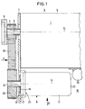
- the sewing machine 1 shown in FIG. 1 is a so-called overlock sewing machine, which is attached to a table top 2 of a sewing machine table.
- the sewing machine 1 has a drive shaft 3, on which a toothed belt wheel 4 and a hand wheel 5 are attached, specifically outside the housing 6 of the sewing machine 1, from which the drive shaft 3 protrudes.
- a support plate 7 for an add-on motor 8 is attached to the housing 6 and extends laterally and - based on the operating side 9 - to the rear 10 of the sewing machine 1.
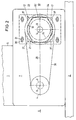
- the add-on motor 8 has a motor housing 11. At one end it is provided in the usual manner with an approximately square housing flange 12 which is integrally connected to the housing 11. From this flange 12, a drive shaft journal 13 emerges concentrically from the motor housing 11. The motor axis 14 and the axis 15 of the drive shaft 3 of the sewing machine 1 run parallel to one another. A centering annular web 16 projecting from the housing flange 12 is formed concentrically with the motor axis 14. As can be seen in FIG. 2, the side edges 17 of the housing flange 12 each run approximately tangentially to the outer contour 18 of the housing 11. Only in the corner regions of the side edges 17 does the flange 12 project beyond the outer contour 18 of the housing 11. In each of these areas there is one outside the outer contour 18 lying bore 19 formed in the flange 12.
- an adapter flange 20 which has an opening 21 whose shape is adapted to the outer contour 18 of the motor housing 11. Furthermore, the adapter flange 20 has a recess 22, the depth a of which corresponds to the thickness b of the housing flange 12. Due to the configuration described, the adapter flange 20 can be pushed over the latter from the side 23 of the motor housing 11 opposite the shaft journal 13 until the recess 22 receives the housing flange 12 and the contact surface 24 of the adapter flange 20 is flush with the end face 25 of the housing -Flansches 12, as can be seen in FIG. 3.
- the adapter flange 20 In the adapter flange 20 threaded bores 26 are formed which are aligned with the bores 19 in the flange 12, so that the adapter flange 20 and the housing flange 12 can be connected to one another by means of countersunk screws 27 which do not have the end face 25 of the housing flange 12 project.
- the total thickness c of the adapter flange 20 is significantly greater than the depth a or the thickness b.
- Threaded bores 29 are formed on the adapter flange 20 outside the outer contour 18 of the motor housing 11 and at a sufficient distance from the common plane 28 of the axes 14 and 15.
- In the support plate 7 are congruent with the threaded holes 29 extending parallel to the plane 28 elongated holes 30 through which the fastening screws 31 are screwed into the threaded holes 29.
- the drive shaft journal 13 passes through an elongated hole recess 32 in the support plate 7.
- the centering ring web 16 projects into this recess 32 in the support plate 7, so that after attachment of the add-on motor 8 together with the adapter flange 20 to the support plate 7 Contact surface 24 abuts the support plate 7.
- the threaded screws 31 are then screwed on in the manner mentioned.
- a toothed belt pinion 34 is fixed in a rotationally fixed manner on the shaft journal 13 and a toothed belt 35 is placed over the toothed belt wheel 4 and the toothed belt pinion 34.
- the add-on motor 8 is then pushed away from the housing 6 of the sewing machine 1 until the toothed belt 35 is tensioned. Then be the fastening screws 31 tightened. Since the tensioning of the toothed belt 35 can only take place after the assembly of the toothed belt pinion 34 on the shaft journal 13, the elongated holes 30 and the threaded bores 29 must lie outside the border of the toothed belt pinion 34 with toothed belt 35, which requires the use of an adapter flange 20 at all.
- a functional part 36 of the sewing machine 1 is located directly adjacent to the side 23 of the motor housing 11 opposite the shaft journal 13 on the housing 6 of the sewing machine 1, which in the present case is a pneumatic cylinder for a Foot ventilation of the sewing machine 1 is.
- This functional part 36 extends behind the side 23 of the housing 11, so that an attachment of the add-on motor 8 to the support plate 6 would not be possible if an adapter flange 20 had been attached to the end face 25 of the housing flange 12, since then the Total length L of the add-on motor 8 would have become too large. Due to the described design, the total length L can be shortened by 5 to 10 mm, which is of considerable importance in the cramped installation conditions on sewing machines for commercial, in particular industrial, use.
- FIGS. 4 to 6 an exemplary embodiment of an adapter flange 20 ′ is shown in FIGS. 4 to 6, which corresponds in substantial parts to the adapter flange 20. Identical parts are therefore identified with identical reference numbers without a renewed description; structurally similar parts are identified by the same reference numbers with a prime.
- the adapter flange 20 ' is divided in a central plane extending through the motor axis 14 and consists of two flange parts 20a and 20b.
- Everyone Flange parts 20a and 20b are provided with mutually overlapping and complementary webs 38, 39 which complement one another to form the complete cross section of the adapter flange 20 '. If the two flange parts 20a, 20b are joined together to form the adapter flange 20 ', then the two webs 38, 39 each lie with two fitting and centering surfaces 40, 41.
- Each web 39 of the flange part 20b has a bore 42 which also has a recess 43 for the head 44 of a connecting screw 45.
- a threaded bore 46 is formed in each web 38 of the flange part 20a, into which a connecting screw 45 is screwed after the two flange parts 20a and 20b have been joined, as can be seen in particular from FIG. 6.
- a centering recess 47 formed by a counterbore is formed on the mating and centering surface 40 of the webs 38 - aligned with the threaded bore 46 - .
- the two flange parts 20a, 20b are pushed laterally, that is to say transversely to the motor axis 14, over the motor housing 11 and are connected to one another in the manner described by means of the connecting screws 45.
- This adapter flange 20 ' is then screwed to the housing flange 12, as already described above.
Abstract
Description
Die Erfindung betrifft einen Anbau-Motor für Nähmaschinen.The invention relates to an add-on motor for sewing machines.
Derartige Anbau-Motoren werden üblicherweise am Gehäuse von Nähmaschinen angebaut, so daß die Achse des Motors und die Achse der Armwelle der Nähmaschine parallel zueinander verlaufen. Die Drehmomentenübertragung erfolgt mittels eines Zahnriementriebes, wozu auf einem aus dem Motor-Gehäuse des Anbau-Motors herausragenden Antriebs-Wellenzapfen ein Zahnriemenritzel befestigt wird. Das Zahnriemenritzel und ein zugeordnetes, auf der Armwelle der Nähmaschine angebrachtes Zahnriemenrad liegen fluchtend zueinander. Der Anbau-Motor wird an einer Trageinrichtung, in der Regel einer Tragplatte, befestigt, die wiederum am Gehäuse der Nähmaschine angebracht ist. An serienmäßigen Anbau-Motoren sind sehr kleine, in der Regel quadratische Gehäuse-Flansche ausgebildet, deren Seitenkanten etwa tangential zur Außenkontur des Motor-Gehäuses verlaufen, so daß nur im Bereich der Ecken der Seitenkanten über das Motor-Gehäuse überstehende Bereiche vorhanden sind, wo Bohrungen bzw. Gewindebohrungen zur Befestigung des Anbau-Motors an der Trageinrichtung ausgebildet werden können. Da die Zahnriemenritzel in der Regel einen die Außenkontur des Motors überragenden Durchmesser aufweisen, ist eine direkte Befestigung der Anbau-Motoren an den erwähnten Tragplatten von der Seite des Zahnriemenritzels her nicht möglich, da ein Spannen der Zahnriemen durch Verschieben des Anbau-Motors relativ zur Nähmaschine und ein anschließendes Festschrauben des Anbau-Motors nicht möglich ist, da die Bohrungen des Gehäuse-Flansches von dem Zahnriemenritzel überdeckt werden. Aus diesem Grunde ist es üblich, auf den Gehäuse-Flansch einen größeren Adapterflansch aufzuschrauben, der das Zahnriemenritzel überragt, so daß nach der vollständigen Montage ein Spannen des Zahnriemens und ein anschließendes endgültiges Festschrauben des Anbau-Motors an der Tragplatte möglich ist. In zahlreichen Fällen herrschen an Nähmaschinen, und zwar insbesondere an gewerblichen Nähmaschinen, und zwar insbesondere solchen für den industriellen Einsatz, sehr enge Einbauverhältnisse, da an der Nähmaschine zahlreiche Funktionselemente montiert sind. Es handelt sich hierbei um Elemente für besondere Funktionen der Nähmaschine, wie beispielsweise Fußlüftung. Diese zusätzlichen Funktionselemente lassen es nicht zu, daß bei einer vorgegebenen Gesamtlänge eines Anbau-Motors noch zusätzlich ein Adapterflansch vor die Stirnseite des Gehäuse-Flansches gesetzt wird, ohne die Gesamtlänge des Motors zu vergrößern.Such add-on motors are usually mounted on the housing of sewing machines, so that the axis of the motor and the axis of the arm shaft of the sewing machine run parallel to one another. The torque is transmitted by means of a toothed belt drive, for which purpose a toothed belt pinion is attached to a drive shaft journal protruding from the motor housing of the add-on motor. The toothed belt sprocket and an associated toothed belt wheel attached to the arm shaft of the sewing machine are in alignment with one another. The add-on motor is attached to a support device, usually a support plate, which in turn is attached to the housing of the sewing machine. On standard add-on motors, very small, usually square housing flanges are formed, the side edges of which run approximately tangentially to the outer contour of the motor housing, so that there are only protruding areas in the area of the corners of the side edges above the motor housing, where Bores or threaded bores can be formed for fastening the add-on motor to the support device. Since the toothed belt sprockets generally have a diameter that projects beyond the outer contour of the motor, direct attachment of the add-on motors to the support plates mentioned from the side of the toothed belt sprocket is not possible, since the toothed belts can be tensioned by moving the add-on motor relative to the sewing machine and a subsequent screwing of the add-on motor is not possible because the Bores of the housing flange are covered by the toothed belt pinion. For this reason, it is customary to screw a larger adapter flange onto the housing flange, which projects beyond the toothed belt sprocket, so that after the complete assembly, tensioning of the toothed belt and subsequent final screwing of the add-on motor to the support plate is possible. In numerous cases there are very tight installation conditions on sewing machines, in particular on commercial sewing machines, in particular those for industrial use, since numerous functional elements are mounted on the sewing machine. These are elements for special functions of the sewing machine, such as foot ventilation. These additional functional elements do not allow an adapter flange to be additionally placed in front of the end face of the housing flange for a given total length of an add-on motor without increasing the overall length of the motor.
Der Erfindung liegt daher die Aufgabe zugrunde, einen Anbau-Motor mit Adapterflansch so auszugestalten, daß die Gesamtlänge des Anbau-Motors durch den zusätzlichen Adapterflansch nicht vergrößert wird.The invention is therefore based on the object of designing an add-on motor with an adapter flange so that the overall length of the add-on motor is not increased by the additional adapter flange.
Diese Aufgabe wird erfindungsgemäß durch die Merkmale im Anspruch 1 gelöst. Der Kern der Erfindung besteht darin, daß der Adapterflansch so ausgestaltet ist, daß er von der dem Austritt des Antriebs-Wellenzapfens entgegengesetzten Ende, gleichsam also vom hinteren Ende des Motors her, über das Motor-Gehäuse geschoben wird und den Gehäuses-Flansch in sich aufnimmt.This object is achieved by the features in
Die Aufgabe wird erfindungsgemäß weiterhin durch die Merkmale im Anspruch 2 gelöst. Der Kern dieser Erfindung besteht darin, daß der Adapterflansch durch Teilung so ausgestaltet ist, daß seine Flanschteile seitlich und zwar hinter dem Gehäuse-Flansch über das Motor-Gehäuse geschoben und dort zu einem Adapterflansch vereinigt werden. Letzterer wird dann ebenfalls von hinten über den Gehäuse-Flansch des Motor-Gehäuses geschoben und mit diesem verbunden.The object is further achieved by the features in claim 2. The essence of this invention is that the adapter flange is designed by division so that its flange parts are pushed laterally behind the housing flange over the motor housing and are combined there to form an adapter flange. The latter is then also pushed from behind over the housing flange of the motor housing and connected to it.
Die Unteransprüche geben vorteilhafte Ausgestaltungen wieder.The sub-claims reflect advantageous refinements.
Weitere Merkmale, Einzelheiten und Vorteile der Erfindung ergeben sich aus der nachfolgenden Beschreibung zweier Ausführungsbeispiele anhand der Zeichnung. Es zeigt
- Fig. 1
- einen Teil einer Nähmaschine mit einem Anbau-Motor in Draufsicht,
- Fig. 2
- eine Stirnansicht der Nähmaschine mit Anbau-Motor gemäß dem Sichtpfeil II in Fig. 1,
- Fig. 3
- den Anbau-Motor in einer Darstellung entsprechend dem Sichtpfeil III in Fig. 1 in teilweise aufgebrochener Darstellung,
- Fig. 4
- eine zweite Ausführungsform eines Adapterflansches in Draufsicht,
- Fig. 5
- einen Schnitt durch den Adapterflansch entsprechend der Schnittlinie V-V- in Fig. 4 und
- Fig. 6
- einen Schnitt durch den Adapterflansch entsprechend der Schnittlinie VI-VI in Fig. 4.
- Fig. 1
- part of a sewing machine with a built-on motor in top view,
- Fig. 2
- 3 shows an end view of the sewing machine with a built-on motor according to the arrow II in FIG. 1,
- Fig. 3
- the add-on motor in a representation according to the arrow III in Fig. 1 in a partially broken representation,
- Fig. 4
- a second embodiment of an adapter flange in plan view,
- Fig. 5
- a section through the adapter flange according to the section line VV- in Fig. 4 and
- Fig. 6
- a section through the adapter flange according to section line VI-VI in Fig. 4th
Bei der in Fig. 1 dargestellten Nähmaschine 1 handelt es sich um eine sogenannte Überwendlich-Nähmaschine, die auf einer Tischplatte 2 eines Nähmaschinen-Tisches angebracht ist. Die Nähmaschine 1 weist eine Antriebswelle 3 auf, auf der ein Zahnriemenrad 4 und ein Handrad 5 angebracht sind, und zwar außerhalb des Gehäuses 6 der Nähmaschine 1, aus dem die Antriebswelle 3 herausragt. Am Gehäuse 6 ist eine Tragplatte 7 für einen Anbau-Motor 8 befestigt, die sich seitlich und - bezogen auf die Bedienungsseite 9 - zur Rückseite 10 der Nähmaschine 1 erstreckt.The
Der Anbau-Motor 8 weist ein Motor-Gehäuse 11 auf. An einem Ende ist er in der üblichen Weise mit einem einstückig mit dem Gehäuse 11 verbundenen etwa quadratischen Gehäuse-Flansch 12 versehen. Aus diesem Flansch 12 tritt konzentrisch ein Antriebs-Wellenzapfen 13 aus dem Motor-Gehäuse 11 heraus. Die Motorachse 14 und die Achse 15 der Antriebswelle 3 der Nähmaschine 1 verlaufen parallel zueinander. Konzentrisch zur Motorachse 14 ist am Gehäuse-Flansch 12 ein von diesem vorspringender Zentrier-Ringsteg 16 ausgebildet. Wie Fig. 2 entnehmbar ist, verlaufen die Seitenkanten 17 des Gehäuse-Flansches 12 jeweils etwa tangential zur Außenkontur 18 des Gehäuses 11. Lediglich in den Eckbereichen der Seitenkanten 17 steht der Flansch 12 über die Außenkontur 18 des Gehäuses 11 vor. In diesen Bereichen ist jeweils eine außerhalb der Außenkontur 18 liegende Bohrung 19 im Flansch 12 ausgebildet.The add-on motor 8 has a
Zur Befestigung des Anbau-Motors 8 an der Tragplatte 7 ist ein Adapterflansch 20 vorgesehen, der eine Öffnung 21 aufweist, die in ihrer Formgebung der Außenkontur 18 des Motor-Gehäuses 11 angepaßt ist. Des weiteren weist der Adapterflansch 20 eine Vertiefung 22 auf, deren Tiefe a der Dicke b des Gehäuse-Flansches 12 entspricht. Aufgrund der geschilderten Ausgestaltung kann der Adapterflansch 20 von der dem Wellenzapfen 13 entgegengesetzten Seite 23 des Motor-Gehäuses 11 über letzteres geschoben werden, bis die Vertiefung 22 den Gehäuse-Flansch 12 aufnimmt und die Anlagefläche 24 des Adapterflansches 20 bündig mit der Stirnseite 25 des Gehäuse-Flansches 12 liegt, wie Fig. 3 entnehmbar ist. Im Adapterflansch 20 sind Gewindebohrungen 26 ausgebildet, die fluchtend mit den Bohrungen 19 im Flansch 12 liegen, so daß der Adapterflansch 20 und der Gehäuse-Flansch 12 mittels Senkkopf-Schrauben 27 miteinander verbunden werden können, die nicht über die Stirnseite 25 des Gehäuse-Flansches 12 vorstehen. Die Gesamtdicke c des Adapterflansches 20 ist deutlich größer als die Tiefe a bzw. die Dicke b.To attach the add-on motor 8 to the
An dem Adapterflansch 20 sind außerhalb der Außenkontur 18 des Motor-Gehäuses 11 und jeweils in ausreichendem Abstand von der gemeinsamen Ebene 28 der Achsen 14 und 15 Gewindebohrungen 29 ausgebildet. In der Tragplatte 7 sind deckungsgleich mit den Gewindebohrungen 29 parallel zur Ebene 28 verlaufende Langlöcher 30 ausgebildet, durch die Befestigungsschrauben 31 hindurch in die Gewindebohrungen 29 geschraubt werden. Der Antriebs-Wellenzapfen 13 durchsetzt eine Langloch-Ausnehmung 32 in der Tragplatte 7. Der Zentrier-Ringsteg 16 ragt in diese Ausnehmung 32 in der Tragplatte 7 hinein, so daß nach dem Ansetzen des Anbau-Motors 8 samt Adapterflansch 20 an die Tragplatte 7 die Anlagefläche 24 an der Tragplatte 7 anliegt. Anschließend werden die Gewindeschrauben 31 in der angesprochenen Weise angeschraubt. Es wird weiterhin ein Zahnriemenritzel 34 drehfest auf dem Wellenzapfen 13 befestigt und ein Zahnriemen 35 über das Zahnriemenrad 4 und das Zahnriemenritzel 34 gelegt. Anschließend wird der Anbau-Motor 8 vom Gehäuse 6 der Nähmaschine 1 weggeschoben, bis der Zahnriemen 35 gespannt ist. Anschließend werden die Befestigungsschrauben 31 festgezogen. Da das Spannen des Zahnriemens 35 erst nach der Montage des Zahnriemenritzels 34 auf dem Wellenzapfen 13 erfolgen kann, müssen die Langlöcher 30 und die Gewindebohrungen 29 außerhalb der Umrandung des Zahnriemenritzels 34 mit Zahnriemen 35 liegen, was überhaupt den Einsatz eines Adapterflansches 20 bedingt.Threaded
Wie Fig. 1 entnehmbar ist, befindet sich unmittelbar benachbart zu der dem Wellenzapfen 13 entgegengesetzten Seite 23 des Motor-Gehäuses 11 am Gehäuse 6 der Nähmaschine 1 ein Funktionsteil 36 der Nähmaschine 1, wobei es sich im vorliegenden Fall um einen Pneumatik-Zylinder für eine Fußlüftung der Nähmaschine 1 handelt. Dieses Funktionsteil 36 erstreckt sich hinter die Seite 23 des Gehäuses 11, so daß ein Anbau des Anbau-Motors 8 an die Tragplatte 6 nicht möglich wäre, wenn ein Adapterflansch 20 an die Stirnseite 25 des Gehäuse-Flansches 12 angesetzt worden wäre, da dann die Gesamtlänge L des Anbau-Motors 8 zu groß geworden wäre. Durch die geschilderte Ausgestaltung kann die Gesamtlänge L um 5 bis 10 mm verkürzt werden, was bei den beengten Einbauverhältnissen an Nähmaschinen für den gewerblichen, und zwar insbesondere industriellen Einsatz von erheblicher Bedeutung ist.As can be seen in FIG. 1, a
Es kann in der Praxis vorkommen, daß am Motor-Gehäuse 11 über dessen sonstiges Außenprofil hinausragende Vorsprünge ausgebildet sind, die ein Überschieben des Adapterflansches 20 von der Seite 23 her über das Motor-Gehäuse ausschließen. In solchen Fällen wird ein Aufschieben des Adapterflansches wegen der an diesem ausgebildeten, die Gewindebohrungen 26 tragenden, mit dem Gehäuse-Flansch 12 überlappende Eckabschnitte 37 behindert. Für solche Fälle ist in den Fig. 4 bis 6 ein Ausführungsbeispiel eines Adapterflansches 20' dargestellt, der mit dem Adapterflansch 20 in wesentlichen Teilen übereinstimmt. Identische Teile werden daher ohne erneute Beschreibung mit identischen Bezugsziffern bezeichnet; konstruktiv ähnliche Teile werden mit gleichen Bezugsziffern mit einem hochgesetzten Strich bezeichnet.In practice it may happen that protrusions are formed on the
Der Adapterflansch 20' ist in einer durch die Motorachse 14 reichenden Mittelebene geteilt und besteht aus zwei Flanschteilen 20a und 20b. Jeder Flanschteil 20a und 20b ist mit einander überlappenden und sich gemeinsam zum vollständigen Querschnitt des Adapterflansches 20' ergänzenden komplementären Stegen 38, 39 versehen. Wenn die beiden Flanschteile 20a, 20b zum Adapterflansch 20' zusammengefügt sind, dann liegen die je zwei Stege 38, 39 mit zwei Paß- und Zentrier-Flächen 40, 41 aneinander. Jeder Steg 39 des Flanschteiles 20b weist eine Bohrung 42 auf, die auch eine Ausnehmung 43 für den Kopf 44 einer Verbindungsschraube 45 aufweist. Mit der Bohrung 42 fluchtend ist in jedem Steg 38 des Flanschteiles 20a eine Gewindebohrung 46 ausgebildet, in die eine Verbindungsschraube 45 nach dem Zusammenfügen der beiden Flanschteile 20a und 20b geschraubt wird, wie insbesondere aus Fig. 6 hervorgeht.The adapter flange 20 'is divided in a central plane extending through the
Aus Fig. 5 ist erkennbar, daß an der Paß- und Zentrier-Fläche 40 der Stege 38 - fluchtend mit der Gewindebohrung 46 - eine durch eine Senkbohrung gebildete Zentrierausnehmung 47 ausgebildet ist. Dieser entspricht ein in der Form angepaßter Zentriervorsprung 48, der an den Paß- und Zentrier-Flächen 41 jeweils fluchtend mit der Bohrung 42 ausgebildet ist. Dieser Zentriervorsprung 48 greift jeweils beim Zusammenfügen der Flanschteile 20a, 20b in die entsprechende Zentrierausnehmung 47 ein, wodurch die beiden Flanschteile 20a, 20b exakt in ihrer Lage zueinander festgelegt und damit zu einem stets gleichen Adapterflansch 20' gestaltet werden.From Fig. 5 it can be seen that on the mating and centering
Zur Montage am Gehäuse-Flansch 12 des Motors 8 werden die beiden Flanschteile 20a , 20b seitlich, also quer zur Motorachse 14, über das Motor-Gehäuse 11 geschoben und in der geschilderten Weise mittels der Verbindungsschrauben 45 miteinander verbunden. Anschließend wird dieser Adapterflansch 20' an den Gehäuse-Flansch 12 geschraubt, wie bereits oben beschrieben.For mounting on the
Claims (8)
wobei die Anlagefläche (24) des Adapterflansches (20, 20') und die Stirnseite (25) des Gehäuse-Flansches (12) bündig miteinander ausgebildet sind.Add-on motor according to claim 1 or 2,
the contact surface (24) of the adapter flange (20, 20 ') and the end face (25) of the housing flange (12) being designed to be flush with one another.
wobei auf dem Antriebs-Wellenzapfen (13) ein Zahnriemenritzel (34) drehfest befestigbar ist, und
wobei außerhalb der Kontur des Zahnriemenritzels (34) am Adapterflansch (20, 20') Gewindebohrungen (29) für eine Befestigung an einer Trageinrichtung (7) einer Nähmaschine (1) ausgebildet sind.Add-on motor according to claim 1 or 2,
wherein a toothed belt pinion (34) can be fastened in a rotationally fixed manner on the drive shaft journal (13), and
wherein outside the contour of the toothed belt pinion (34) on the adapter flange (20, 20 ') threaded bores (29) are formed for attachment to a carrying device (7) of a sewing machine (1).
wobei die Flanschteile (20a, 20b) des Adapterflansches (20') mit einander komplementären Stegen (38, 39) versehen sind.Add-on motor according to claim 2,
the flange parts (20a, 20b) of the adapter flange (20 ') being provided with mutually complementary webs (38, 39).
wobei die Stege (38, 39) mit einander komplementären Paß- und Zentrier-Flächen (40, 41) versehen sind.Add-on motor according to claim 5,
wherein the webs (38, 39) are provided with complementary fitting and centering surfaces (40, 41).
wobei eine Paß- und Zentrier-Fläche (40) mit einer Zentrierausnehmung (47) und die zugeordnete andere Paß- und Zentrier-Fläche (41) mit einem in die Zentrierausnehmung (47) eingreifenden Zentriervorsprung (48) versehen ist.Add-on motor according to claim 6,
wherein a fitting and centering surface (40) is provided with a centering recess (47) and the associated other fitting and centering surface (41) is provided with a centering projection (48) engaging in the centering recess (47).
wobei jeweils ein Steg (38) eines Flanschteiles (20a) mit einem Steg (39) des anderen Flanschteiles (20b) mittels einer Verbindungsschraube (45) verbunden ist.Add-on motor according to one of claims 5 to 7,
wherein a web (38) of one flange part (20a) is connected to a web (39) of the other flange part (20b) by means of a connecting screw (45).
Applications Claiming Priority (4)
| Application Number | Priority Date | Filing Date | Title |
|---|---|---|---|
| DE29514444U | 1995-09-08 | ||
| DE29514444 | 1995-09-08 | ||
| DE29604747U | 1996-03-14 | ||
| DE29604747U DE29604747U1 (en) | 1995-09-08 | 1996-03-14 | Add-on motor for sewing machines |
Publications (1)
| Publication Number | Publication Date |
|---|---|
| EP0761861A1 true EP0761861A1 (en) | 1997-03-12 |
Family
ID=26058202
Family Applications (1)
| Application Number | Title | Priority Date | Filing Date |
|---|---|---|---|
| EP96114226A Withdrawn EP0761861A1 (en) | 1995-09-08 | 1996-09-05 | Motor mounting for sewing machines |
Country Status (2)
| Country | Link |
|---|---|
| US (1) | US5711237A (en) |
| EP (1) | EP0761861A1 (en) |
Families Citing this family (1)
| Publication number | Priority date | Publication date | Assignee | Title |
|---|---|---|---|---|
| US6865995B2 (en) * | 2002-10-30 | 2005-03-15 | Jui-Jung Chuo | Structure of a motor driven driving mechanism of a sewing machine |
Citations (2)
| Publication number | Priority date | Publication date | Assignee | Title |
|---|---|---|---|---|
| DE816474C (en) * | 1950-07-07 | 1951-10-11 | Max Schwab | Electric sewing machine equipment |
| US3326158A (en) * | 1964-05-28 | 1967-06-20 | Singer Co | Sewing machine motor mounting system |
Family Cites Families (6)
| Publication number | Priority date | Publication date | Assignee | Title |
|---|---|---|---|---|
| DE520871C (en) * | 1924-02-08 | 1931-03-16 | Aeg | Loose mounting flange for attaching electric drive motors to suitably designed parts of work machines |
| DE704283C (en) * | 1936-04-25 | 1941-03-27 | Richard Heike | Electric motor, the power transmission of which is carried out by a traction device that is tensioned by an eccentric bearing of the motor housing |
| JPH0798111B2 (en) * | 1986-06-14 | 1995-10-25 | 岩瀬プリンス株式会社 | Sewing machine such as futon |
| DE3819975C2 (en) * | 1988-06-11 | 1995-11-09 | Duerkopp Adler Ag | Sewing machine |
| US4873932A (en) * | 1989-02-01 | 1989-10-17 | Ssmc Inc. | Stepper driven stitch patterning mechanism for sewing machines using spiral cam groove and follower |
| US5281878A (en) * | 1992-08-27 | 1994-01-25 | Schaeffer George L | Adaptor for hydraulic power tilt/trim reservoirs |
-
1996
- 1996-09-05 EP EP96114226A patent/EP0761861A1/en not_active Withdrawn
- 1996-09-06 US US08/706,695 patent/US5711237A/en not_active Expired - Fee Related
Patent Citations (2)
| Publication number | Priority date | Publication date | Assignee | Title |
|---|---|---|---|---|
| DE816474C (en) * | 1950-07-07 | 1951-10-11 | Max Schwab | Electric sewing machine equipment |
| US3326158A (en) * | 1964-05-28 | 1967-06-20 | Singer Co | Sewing machine motor mounting system |
Also Published As
| Publication number | Publication date |
|---|---|
| US5711237A (en) | 1998-01-27 |
Similar Documents
| Publication | Publication Date | Title |
|---|---|---|
| DE102016112778B4 (en) | Bicycle component | |
| DE4219956C2 (en) | Cutting device for a motor chain saw | |
| EP1824763B1 (en) | Conveyor device | |
| DE19542109A1 (en) | Rail=fixing device to vehicle roof | |
| DE3328338A1 (en) | Device for adjusting a first component relative to a second component | |
| DE4202775C2 (en) | Hydraulic clamping device | |
| DE4108663A1 (en) | TRIPLE-DESIGNED GUIDE RAIL FOR MOTOR CHAIN SAWS | |
| DE3420146A1 (en) | STEERING CHAIN CONNECTION | |
| EP0761861A1 (en) | Motor mounting for sewing machines | |
| DE3204677C2 (en) | Spacer sleeve for attaching a fitting part to a hollow profile | |
| DE4236282C1 (en) | Screw coupling device on a plastic injection molding machine | |
| DE3617983A1 (en) | Connection of motor vehicle drive or output shaft sections | |
| EP0123209A2 (en) | Auxiliary mounting device for tracked chain vehicles | |
| EP0120996A1 (en) | Conveyor | |
| DE2114717A1 (en) | Device for fastening and adjusting printing plates on printing cylinders | |
| DE4104217A1 (en) | Friction shaft coupling to external component | |
| DE3829526A1 (en) | CONNECTING ROD-CRANK-DEVICE, IN PARTICULAR FOR OPERATING AN AIR VALVE WITHIN A HEATING AND AIR CONDITIONING FOR MOTOR VEHICLES | |
| DE19608290C1 (en) | Conveyor using round steel chain, driving conveyor elements | |
| EP0447426B1 (en) | Perforator | |
| DE2438738C3 (en) | Adjustable braking device for a vent window in a vehicle | |
| DE19846555A1 (en) | Tensioning device for chain or belt of motorized hand-held tool, with length of journal made so that bolt only projects when journal is in aperture of washer | |
| EP0324112B1 (en) | Adjusting device for a setting bolt | |
| DE19505159C2 (en) | Device for fastening a wiper bearing for a wiper shaft of a windscreen wiper | |
| DE3728324C2 (en) | ||
| DE19516689C1 (en) | Tool for re=cutting damaged bolt threads |
Legal Events
| Date | Code | Title | Description |
|---|---|---|---|
| PUAI | Public reference made under article 153(3) epc to a published international application that has entered the european phase |
Free format text: ORIGINAL CODE: 0009012 |
|
| AK | Designated contracting states |
Kind code of ref document: A1 Designated state(s): DE GB IT PT |
|
| RBV | Designated contracting states (corrected) |
Designated state(s): DE GB IT PT |
|
| 17P | Request for examination filed |
Effective date: 19970528 |
|
| RBV | Designated contracting states (corrected) |
Designated state(s): DE GB IT PT |
|
| STAA | Information on the status of an ep patent application or granted ep patent |
Free format text: STATUS: THE APPLICATION HAS BEEN WITHDRAWN |
|
| 18W | Application withdrawn |
Withdrawal date: 20010817 |