EP0761449B1 - Segmentiertes flexibles Heizelement zum Trocknen eines gedruckten Bildes - Google Patents
Segmentiertes flexibles Heizelement zum Trocknen eines gedruckten Bildes Download PDFInfo
- Publication number
- EP0761449B1 EP0761449B1 EP96306201A EP96306201A EP0761449B1 EP 0761449 B1 EP0761449 B1 EP 0761449B1 EP 96306201 A EP96306201 A EP 96306201A EP 96306201 A EP96306201 A EP 96306201A EP 0761449 B1 EP0761449 B1 EP 0761449B1
- Authority
- EP
- European Patent Office
- Prior art keywords
- heater
- recording medium
- print zone
- support
- support member
- Prior art date
- Legal status (The legal status is an assumption and is not a legal conclusion. Google has not performed a legal analysis and makes no representation as to the accuracy of the status listed.)
- Expired - Lifetime
Links
Images


Classifications
-
- B—PERFORMING OPERATIONS; TRANSPORTING
- B41—PRINTING; LINING MACHINES; TYPEWRITERS; STAMPS
- B41J—TYPEWRITERS; SELECTIVE PRINTING MECHANISMS, i.e. MECHANISMS PRINTING OTHERWISE THAN FROM A FORME; CORRECTION OF TYPOGRAPHICAL ERRORS
- B41J11/00—Devices or arrangements of selective printing mechanisms, e.g. ink-jet printers or thermal printers, for supporting or handling copy material in sheet or web form
- B41J11/0015—Devices or arrangements of selective printing mechanisms, e.g. ink-jet printers or thermal printers, for supporting or handling copy material in sheet or web form for treating before, during or after printing or for uniform coating or laminating the copy material before or after printing
- B41J11/002—Curing or drying the ink on the copy materials, e.g. by heating or irradiating
- B41J11/0024—Curing or drying the ink on the copy materials, e.g. by heating or irradiating using conduction means, e.g. by using a heated platen
- B41J11/00244—Means for heating the copy materials before or during printing
Definitions
- This invention relates generally to a printing apparatus in accordance with the generic clause of claim 1.
- a printing apparatus is already known from US-A-5 406 321 which will be discussed lateron in more detail.
- liquid inks and particularly those used in thermal ink jet printing include a colorant or dye and a liquid which is typically an aqueous liquid vehicle, such as water, and/or a low vapor pressure solvent.
- the ink is deposited on the substrate to form an image in the form of text and/or graphics.
- the liquid component is removed from the ink and the paper to fix the colorant to the substrate by either natural air drying or by active drying.
- natural air drying the liquid component of the ink deposited on the substrate is allowed to evaporate and to penetrate into the substrate naturally without mechanical assistance.
- active drying the recording medium is exposed to heat energy of various types which can include infrared heating, conductive heating and heating by microwave energy.
- Active drying of the image can occur either during the imaging process or after the image has been made on the recording medium.
- the recording medium can be preheated before an image has been made to precondition the recording medium in preparation for the deposition of ink.
- Preconditioning of the recording medium typically prepares the recording medium for receiving ink by driving out excess moisture which can be present in a recording medium such as paper. Not only does this preconditioning step reduce the amount of time necessary to dry the ink once deposited on the recording medium, but this step also improves image quality by reducing paper cockle and curl which can result from too much moisture remaining in the recording medium.
- FIG. 1 illustrates a schematic representation of a thermal ink jet printer 10 in a side elevation view.
- a translating ink jet printhead 12 printing black and/or colored inks is supported by a carriage 14 which moves back and forth across a recording medium 16, for instance, sheets of paper or transparencies, on a guide rail 18. Multiple printheads printing different colors are also within the scope of this invention.
- the recording medium 16 is moved along a recording medium path through the printer in the direction noted by the arrow 20. Single sheets of the recording medium 16 are fed from a tray 22 by a document feed roll 24.
- the document tray 22 is spring biased by a biasing mechanism 26 which forces the top sheet of the stack of recording sheets held by the tray 22 into contact with the feed roll 24.
- a top recording medium 16 in contact with the feed roll 24 is transported by the feed roll 24 into a chute 28 which is defined by an outer guide member 30 spaced from an inner guide member 32, each of which are curved to thereby reverse the direction of the recording sheets 16 for printing by the printhead 12.
- the recording medium 16 is driven into the nip of a drive roll 34 cooperating with a pinch roll 36 to advance the recording sheet 16 into a print zone 38.
- the print zone 38 is the area directly beneath the printhead 12 where ink droplets 40 are deposited by an array of ink nozzles printing a swath of information and arranged on a front face of the printhead.
- the front face of the printhead is substantially parallel to the recording medium.
- the carriage 14, traveling orthogonally to the recording medium 16 deposits the ink droplets 40 upon the recording medium 16 in an imagewise fashion.
- the printhead 12 receives ink from either an attached ink tank or from an ink supply tube (not shown).
- the image deposited upon the recording medium 16 can include text and/or graphic images, the creation of which is controlled by a controller (not shown), known to those skilled in the art, in response to electrical signals traveling through a ribbon cable 42 coupled to the printhead 12.
- an exit drive roll/pinch roll combination (not shown) or other known means captures the leading edge of the recording medium 16 for transport to an output tray 44 which holds printed recording medium.
- the present invention includes a segmented flexible heater 50 which is located along the inside of the chute 28, in contact with and supported by the inner guide section 32, and which extends through the print zone 38.
- the segmented flexible heater 50 is located within the printer 10 such that the side of the recording medium opposite the side to be printed comes into direct contact with the flexible heater. Heat energy is delivered primarily through conduction.
- the inner guide section 32 can include apertures, such as round holes, diagonally placed slots, or raised areas to thereby shorten warm-up times.
- the segmented flexible heater 50 is arranged within the printer 10 such that a first preheat area 52 is defined to preheat the paper before it enters the print zone area 38.
- a second heat area 54 is defined in the print zone 38 to thereby apply heat energy to the backside of the recording medium 16 during printing.
- the portion of the flexible heater 50 located within the print zone 38 is substantially flat thereby providing a substantially flat uniform contact surface for supporting the recording medium in the print zone 38 during printing. Surface flatness is required to insure adequate paper to heater contact as well as to maintain the critical spacing between the printhead 12 and the recording medium 16.
- the flexible heater 50 is supported by a print zone area heater support 56.
- a first end 58 of the flexible heater 50 is attached to a mounting member 60 which, in turn, is mounted to the inner guide member 32.
- a second end 62 of the flexible heater 50 has attached thereto a spring or tensioning mechanism 64 (here schematically represented) for applying tension to the flexible heater 50.
- the tensioning mechanism 64 not only maintains the necessary surface flatness in the print zone 38, but also maintains the critical spacing between the printhead 12 and the recording medium 16. By stretching the flexible heater 50, the heater 50 is placed in tension to reduce or eliminate buckling or unevenness which can result from thermal expansion that takes place when the flexible heater is activated.
- the flexible heater 50 is placed under tension by the tension mechanism 64 which stretches the flexible heater over a first strut 70 and a second strut 72 positioned perpendicular to the process direction as indicated by arrow 20 and which are parallel with respect to one another.
- the first strut 70 and the second strut 72 are positioned at either side of the print zone 38 and run across the width of the flexible heater 50.
- the flexible heater 50 is pulled to tension in the dimension perpendicular to each of these support surfaces. Since the flexible heater 50 is not physically attached to the surface of the first strut 70 or second strut 72, the heater is free to expand and to contract without creating buckling or corrugation of the heater.
- the heater 50 has the end opposite the tensioning member attached to a rigid member 74, or for instance, the frame of the printer.
- the print zone support 56 incorporates the features illustrated in FIG. 2 for tensioning the flexible heater 50.
- the support 56 includes a first portion 76 corresponding to the first strut 70 and a second portion 78 corresponding to the second strut 72.
- the so called “struts" in the present invention are simply elevated sections of a plastic extrusion that run the width of the print zone from one side of the frame to the other.
- the flexible heater 50 thereby contacts accurately controlled parallel regions of the support 56 at or before and after end of the print zone 38 to form a flat contact surface.
- the flexible heater defines a gap 80 between the bottom surface of the flexible heater and a third portion 82 of the support 56 which extends between the first portion 76 and the second portion 78.
- the gap 80 extends across and beneath the entire width of the recording medium being printed. This gap not only maintains the flatness of the flexible heater within the print zone since the support member 56 does not contact the tensioned flexible heater at this location, but also improves the overall heating efficiency and minimizes the warm-up time of the heater.
- FIG. 3 is a partial schematic perspective view of the printer 10 for illustrating additional features of the heater 50.
- the segmented heater 50 includes a first portion 83, corresponding to the first preheat area 50 of FIG. 1, and a second portion 84, corresponding to the second heat area 54 of FIG. 1.
- the first portion 83 is supported by the inner guide member 32 which creates a curved heating surface used to preheat the recording medium during passage through the chute 28 of FIG. 1.
- the first portion 83 preheats the recording medium and is primarily necessary when printing on stress papers, since the absorption and desorption of water relaxes the internal stresses of the paper and can result in deformation, such as cockle.
- the preheating removes excess moisture from the paper and results in a more dimensionally stable sheet as well as improving ink absorption into the paper.
- Transparencies and certain coated papers do not require preheating and, in fact, can be damaged by excess preheating because of softening.
- the preheat area 83 is, therefore, separately controllable and can either be turned off or can have the heat produced thereby significantly reduced when these type of media are being printed.
- the second portion 84 of the flexible heater 50 generates heat energy having a temperature greater than the first portion 83.
- the second portion 84 provides the primary drying function for driving the liquid from the ink deposited by the printhead 12 in the print zone 38.
- the distance travelled by the recording medium 16 over the second portion 84 is much less than the distance travelled by the recording medium 16 over the first portion 83.
- the long dwell time experienced by a recording medium 16 in the first portion 83 drives any excess moisture from the paper.
- the function of the second portion 84 is primarily to add heat energy to the recording medium while printing to draw excess liquid from the ink. According to the present invention, therefore, a short dwell time of high heat energy follows a long dwell time of low heat energy thereby providing accurately controlled drying for all types of recording medium.
- the first portion 83 of the flexible heater 50 includes a first aperture 85 and a second aperture 86.
- the first aperture 85, as well as the second aperture 86, provide for the continued advancement of the recording medium through the print zone by enabling contact of the pinch roller to the drive roller for picking up the lead edge of the recording medium.
- the amount of heat area provided by the present invention for a preheat zone is increased for the present printer configuration, since an area between the rollers and the print zone heating area can still be heated.
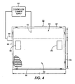
- FIG. 4 illustrates the two segment flexible heater 50 of the present invention.
- the construction of the flexible heater 50 consists of thin circuit wire runs of NiChrome resistive heat generating material.
- the thin layer is sandwiched between a top and a bottom layer of heat resistant polymer such as Kapton(polyimide) or polyester.
- Kapton(polyimide) or polyester The selection of materials is based primarily on the operating temperature of the heater.
- Portions of the heater are organized to supply heat energy according to specific voltages and watt densities.
- the thin configuration for instance, preferably having a thickness of less than 2.54cm (0.1in), allows the heater to follow the radius of the preheat section. Since, the core of the heater must be thin, for instance, less than 25.4 ⁇ m (0.001 in), serpentine shaped NiChrome elements perform well. Orientation of the heat runs in the construction are parallel to the motion of the printhead and perpendicular to the paper motion. The layer sandwiching the NiChrome element provides support for the heater core. The choice of sandwiching materials is primarily driven by the operating temperatures. Kapton (polyimide) is used for high operating temperatures, for instance, greater than 148.9°C (300°F). Polyester, on the other hand, can be used for lower operating temperatures, for instance, approximately 93.3°C (200°F).
- Kapton polyimide
- Polyester on the other hand, can be used for lower operating temperatures, for instance, approximately 93.3°C (200°F).
- the described flexible heater is also known as a foil heater.
- Other types of flexible heaters are within the scope of the present invention.
- any flexible heater having a low thermal mass is acceptable, such as wire resistive elements traversing a support medium, carbon loaded film, metal film photopatterned with runs of graphite material, or conductive material sprayed or doctor bladed on a support medium.
- Attached to the heater 50 is a connecting member 88 which includes electrical connecting leads for connecting to the first portion 83 and the second portion 84. Since the first portion 83 generates heat energy for preheating the paper, a current is applied to the first portion 83 by a controller/current supply module 90. The current applied to the first portion 83 is set to a predetermined level such that the heat energy generated by the first portion 83 is approximately 3.875kWm -2 (2.5Win -2 ). The temperature of this region is not sensed, and consequently, there are no feedback signals for maintaining the temperature of the heat generated by the first portion 83. This portion, however, could include temperature sensing.
- the second portion 84 preferably includes an embedded thermistor 92 for sensing the temperature of the second portion 84.
- the embedded thermistor 92 is connected to the controller/current supply module 90 which receives electrical signals indicating temperature. A current control signal is returned to the second portion 84 through the connecting member 88.
- the electrical signals received from the thermistor indicate the sensed temperature and help maintain the temperature of the second portion 84 at approximately 27-42 degrees Celsius (50-75 degrees Fahrenheit) hotter than the temperature of the first portion 83.
- the heat energy generated by the second region 84 is approximately 7.75Kwm -2 (5Win -2 ).
- a linear distance A of the first first portion 83 in the paper path direction is approximately 6.35cm (2.5in).
- a linear distance B of the second portion 84 in the paper path direction is approximately 2.54 cm (1in).
- Other distances are possible depending on swath width, paper length, heating temperatures, and other know factors affecting drying.
- the second portion 84 is at least twice as wide as the distance covered by the printhead printing a single swath of information perpendicular to the paper path direction.
- the one swath advance print zone located before the actual print zone of the printhead provides for a more accurately controllable heat energy presence on the recording medium.
- a linear distance C is sufficiently wide to adequately heat the width of the paper deposited with ink.
- FIGS. 1, 2 and 3 have illustrated anchoring the flexible heater at the edge 58 and applying tension to the edge 62, it is also possible to apply tension to all four edges of the flexible heater. Consequently, spring loaded mechanisms could be applied not only the second end 62, but also to the first end 58, to a first side edge 94 and a second side edge 96. These edges could include perforations as shown for attaching spring loaded devices thereto.
- segmented flexible heater for drying a printed image on a recording medium moving along a paper path.
- the segmented flexible heater is disposed adjacently to the paper path and includes a first portion for preheating the paper and a second portion for heating a portion of the paper located within a print zone. It is therefore apparent that there has been provided in accordance with the present invention a segmented flexible dryer that satisfies the aims and advantages hereinbefore set forth.
- a segmented flexible heater is not limited to having two portions but can include any number of portions greater than two.
- the temperature selected for the preheat portion and the print area portion can be selected as a function of print mode and media type. For example, a reduced temperature setpoint could be used for non-paper backed transparencies.
- a higher temperature setpoint and improved intercolor bleed performance could be achieved in a high quality print mode which utilizes multi-pass printing where the image is built in two or more passes. These temperature setpoints would be optimized for the particular ink being used.
Landscapes
- Ink Jet (AREA)
- Drying Of Solid Materials (AREA)
- Accessory Devices And Overall Control Thereof (AREA)
Claims (10)
- Drucker (10) zum Drucken auf ein Aufzeichnungsmedium (16), das sich entlang einer Bahn durch eine Druckzone (38) bewegt, umfassend:dadurch gekennzeichnet, dasseinen Druckkopf (12), der so beschaffen ist, dass er Druckfarbe (40) auf das Aufzeichnungsmedium (16) aufbringt ;undeine Heizung (50,83,84), die an der Bahn angeordnet ist, um das Aufzeichnungsmedium (16) zu heizen, wobeidie Heizung (50, 83, 84) segmentiert und flexibel ist und einen ersten Bereich (83) einschließt, der eine erste Heizregion (52) definiert, die das Aufzeichnungsmedium (16) vorheizt und einen zweiten Bereich (84), der eine zweite Heizregion (54) definiert,
der zweite Bereich der flexiblen segmentierten Heizung in der Druckzone (38) angeordnet ist, um das Aufzeichnungsmedium (16) in der Druckzone (38) zu heizen. - Vorrichtung nach Anspruch 1, wobei der erste Bereich (83) Wärmeenergie mit einer ersten Temperatur erzeugt und der zweite Bereich (84) Wärmeenergie mit einer zweiten Temperatur erzeugt, die größer als die erste Temperatur ist, wobei der erste Bereich (83) entlang den Bahn in Richtung der Bewegung des Aufzeichnungsmedium (16) vor dem zweiten Bereich (84) angeordnet ist, und der zweite Bereich (84) der Heizung (50) zu der Druckzone (38) ausgerichtet ist.
- Vorrichtung nach Anspruch 1 oder 2, die weiter zumindest eine Antriebsrolle (34) umfasst, wobei die Heizung (50) zumindest eine Öffnung (85, 86) definiert, durch die die Antriebsrolle (34) das Aufzeichnungsmedium (16) kontaktieren kann, um das Aufzeichnungsmedium (16) entlang der Bahn vorwärts zu bringen.
- Vorrichtung nach einem der vorhergehenden Ansprüche, die weiter ein Steuermodul (90) umfasst, das mit dem zweiten Bereich (84) gekoppelt ist, um die dadurch erzeugte Wärmeenergie zu steuern.
- Vorrichtung nach Anspruch 4, wobei der zweite Bereich (84) eine Temperaturmesseinrichtung (92) einschließt, die mit dem Steuermodul (90) gekoppelt ist, um die Temperatur des zweiten Bereichs (84) gemäß Signalen, die von der Temperaturmesseinrichtung (92) erhalten wurden, zu messen.
- Vorrichtung nach Ansprüchen 4 oder 5, wobei das Steuermodul (90) mit dem ersten Bereich (83) gekoppelt ist, um ihn mit einem vorbestimmten Strom zu versorgen.
- Vorrichtung nach einem der vorhergehenden Ansprüche, die weiter einen Heizungshalter (56, 60, 64, 76, 78, 82) umfasst, um die Heizung (50, 83, 84) an der Bahn zu halten.
- Vorrichtung nach Anspruch 7, wobei der Heizungshalter (56, 60, 64, 76, 78, 82) ein erstes Halteteil (76) und ein zweites Halteteil (78) umfasst, wobei das zweite Halteteil (78) von dem ersten Halteteil (76 )beabstandet ist, und das erste Halteteil (76) und das zweite Halteteil (78) die Heizung (50,83, 84) kontaktieren.
- Vorrichtung nach Anspruch 8, wobei der Heizungshalter (56, 60, 64, 76, 78, 82) weiter ein Spannteil (64) einschließt, das mit der Heizung (50, 83, 84) gekoppelt ist, und diese zwischen dem ersten und zweiten Halteteil (76, 78) spannt.
- Vorrichtung nach Anspruch 8 oder 9, wobei ein Teil (82) des Heizungshalters (56, 60, 64, 76, 78, 82), der zwischen dem ersten Halteteil (76) und dem Teil (78) angeordnet ist, nicht in Kontakt mit Heizung (50, 83, 84) ist, wobei der Teil (82) zu der Druckzone (38) ausgerichtet ist.
Applications Claiming Priority (2)
| Application Number | Priority Date | Filing Date | Title |
|---|---|---|---|
| US08/523,322 US5742315A (en) | 1995-09-05 | 1995-09-05 | Segmented flexible heater for drying a printed image |
| US523322 | 1995-09-05 |
Publications (3)
| Publication Number | Publication Date |
|---|---|
| EP0761449A2 EP0761449A2 (de) | 1997-03-12 |
| EP0761449A3 EP0761449A3 (de) | 1998-07-01 |
| EP0761449B1 true EP0761449B1 (de) | 2001-11-28 |
Family
ID=24084545
Family Applications (1)
| Application Number | Title | Priority Date | Filing Date |
|---|---|---|---|
| EP96306201A Expired - Lifetime EP0761449B1 (de) | 1995-09-05 | 1996-08-27 | Segmentiertes flexibles Heizelement zum Trocknen eines gedruckten Bildes |
Country Status (4)
| Country | Link |
|---|---|
| US (1) | US5742315A (de) |
| EP (1) | EP0761449B1 (de) |
| JP (1) | JPH09123438A (de) |
| DE (1) | DE69617338T2 (de) |
Families Citing this family (26)
| Publication number | Priority date | Publication date | Assignee | Title |
|---|---|---|---|---|
| US6132038A (en) * | 1997-09-02 | 2000-10-17 | Xerox Corporation | Liquid ink printer having a self regulating contact drier |
| US5992973A (en) | 1998-10-20 | 1999-11-30 | Eastman Kodak Company | Ink jet printing registered color images |
| EP0997301A3 (de) | 1998-10-30 | 2000-07-12 | Xerox Corporation | Infrarotfolienheizung zum Trocknen von Tintenstrahlabbildungen auf einem Aufzeichnungsträger |
| US6340225B1 (en) * | 1999-01-19 | 2002-01-22 | Xerox Corporation | Cross flow air system for ink jet printer |
| US6428159B1 (en) | 1999-07-19 | 2002-08-06 | Xerox Corporation | Apparatus for achieving high quality aqueous ink-jet printing on plain paper at high print speeds |
| US6231176B1 (en) * | 1999-10-04 | 2001-05-15 | Xerox Corporation | Self-tensioning flexible heater assembly for drying image bearing substrates in an ink jet printer |
| US6394596B1 (en) | 1999-10-05 | 2002-05-28 | Hewlett-Packard Company | Belt-type media support for a printer |
| US6336722B1 (en) | 1999-10-05 | 2002-01-08 | Hewlett-Packard Company | Conductive heating of print media |
| US6315404B1 (en) | 1999-12-21 | 2001-11-13 | Hewlett-Packard Company | Heated vacuum platen |
| US6328440B1 (en) | 2000-01-07 | 2001-12-11 | Hewlett-Packard Company | Buckling control for a heated belt-type media support of a printer |
| US6361162B1 (en) * | 2000-03-01 | 2002-03-26 | Lexmark International, Inc. | Method and apparatus for fixing ink to a print receiving medium |
| US6536894B1 (en) | 2000-06-06 | 2003-03-25 | Hewlett-Packard Company | Print media heating techniques for a vacuum belt hard copy apparatus |
| DE10056703C2 (de) * | 2000-11-15 | 2002-11-21 | Technoplot Cad Vertriebs Gmbh | Tintenstrahldrucker mit einem Piezo-Druckkopf zum Ausstoßen von Lactat-Tinte auf ein unbeschichtetes Druckmedium |
| US6857803B2 (en) * | 2001-01-08 | 2005-02-22 | Vutek, Inc. | Printing system web guide with a removable platen |
| US6679640B2 (en) | 2001-01-08 | 2004-01-20 | Vutek, Incorporated | Printing system web guide coupling assembly |
| US20030038990A1 (en) * | 2001-08-24 | 2003-02-27 | Scitex Vision Ltd | Convex printing table |
| US20030041962A1 (en) * | 2001-09-05 | 2003-03-06 | John R. Johnson | Digitally printed products and process |
| US6783226B2 (en) * | 2002-09-26 | 2004-08-31 | Xerox Corporation | Curved infrared foil heater for drying images on a recording medium |
| US6932526B2 (en) * | 2003-11-21 | 2005-08-23 | Xerox Corporation | Multi-stage pre-transfer substrate heating assembly |
| JP2006150961A (ja) * | 2004-11-25 | 2006-06-15 | Oce Technol Bv | 受像シートを処理する方法、及び、かかる方法を採用する熱溶解インクジェット印刷装置 |
| US20080024557A1 (en) * | 2006-07-26 | 2008-01-31 | Moynihan Edward R | Printing on a heated substrate |
| US20080223238A1 (en) * | 2007-03-15 | 2008-09-18 | Hewlett-Packard Development Company, Lp | Systems and Methods for Reducing Output Delays Associated With Ink Drying |
| US7828423B2 (en) * | 2007-07-05 | 2010-11-09 | Xerox Corporation | Ink-jet printer using phase-change ink printing on a continuous web |
| US8050167B2 (en) * | 2009-03-04 | 2011-11-01 | Victor Company Of Japan, Limited | Optical device |
| JP2015139997A (ja) * | 2014-01-30 | 2015-08-03 | セイコーエプソン株式会社 | 液体吐出装置 |
| GB201601370D0 (en) | 2016-01-26 | 2016-03-09 | Haydale Graphene Ind Plc | Heater |
Family Cites Families (10)
| Publication number | Priority date | Publication date | Assignee | Title |
|---|---|---|---|---|
| JPS6213536A (ja) * | 1985-07-10 | 1987-01-22 | Nippon Kokan Kk <Nkk> | 雰囲気炉出口シ−ル装置 |
| JPS62130863A (ja) * | 1985-12-02 | 1987-06-13 | Seiko Epson Corp | インクジエツト記録装置 |
| DE3723550A1 (de) * | 1986-07-16 | 1988-01-21 | Trw Inc | Verfahren zur herstellung eines gelenkes |
| JPS6347166A (ja) * | 1986-08-18 | 1988-02-27 | Seiko Epson Corp | 印写装置 |
| US4774523A (en) * | 1987-03-25 | 1988-09-27 | Hewlett-Packard Company | Method and apparatus for uniformly drying ink on paper from an ink jet printer |
| EP0294793B1 (de) * | 1987-06-12 | 1996-10-09 | Canon Kabushiki Kaisha | Aufzeichnungsgerät |
| JPH0262275A (ja) * | 1988-08-30 | 1990-03-02 | Brother Ind Ltd | 記録装置 |
| US4982207A (en) * | 1989-10-02 | 1991-01-01 | Eastman Kodak Company | Heating print-platen construction for ink jet printer |
| ES2092222T3 (es) * | 1992-05-01 | 1996-11-16 | Hewlett Packard Co | Sistema soplante calentado en una impresora de chorro de tinta de color. |
| US5406321A (en) * | 1993-04-30 | 1995-04-11 | Hewlett-Packard Company | Paper preconditioning heater for ink-jet printer |
-
1995
- 1995-09-05 US US08/523,322 patent/US5742315A/en not_active Expired - Lifetime
-
1996
- 1996-08-27 EP EP96306201A patent/EP0761449B1/de not_active Expired - Lifetime
- 1996-08-27 DE DE69617338T patent/DE69617338T2/de not_active Expired - Lifetime
- 1996-08-28 JP JP8245649A patent/JPH09123438A/ja not_active Withdrawn
Also Published As
| Publication number | Publication date |
|---|---|
| DE69617338T2 (de) | 2002-05-08 |
| US5742315A (en) | 1998-04-21 |
| JPH09123438A (ja) | 1997-05-13 |
| DE69617338D1 (de) | 2002-01-10 |
| EP0761449A2 (de) | 1997-03-12 |
| EP0761449A3 (de) | 1998-07-01 |
Similar Documents
| Publication | Publication Date | Title |
|---|---|---|
| EP0761449B1 (de) | Segmentiertes flexibles Heizelement zum Trocknen eines gedruckten Bildes | |
| US5005025A (en) | Printer having means for heating a recording sheet and fixing ink thereon | |
| KR101154216B1 (ko) | 연속적인 매체 웹 가열기 | |
| US6132038A (en) | Liquid ink printer having a self regulating contact drier | |
| US6340225B1 (en) | Cross flow air system for ink jet printer | |
| US6783226B2 (en) | Curved infrared foil heater for drying images on a recording medium | |
| US5754208A (en) | Liquid ink printer having dryer with integral reflector | |
| EP0488415B1 (de) | Fixiervorrichtung und zugehöriges Tintenstrahlaufzeichnungsgerät | |
| US6428158B1 (en) | Liquid ink printer having a heat and hold drier | |
| US6328440B1 (en) | Buckling control for a heated belt-type media support of a printer | |
| JP2001213013A (ja) | プリント媒体真空保持装置、ハードコピー装置及び、真空誘導下位装置を有するハードコピー装置のプリント領域でプリント媒体を加熱する方法 | |
| US6048059A (en) | Variable power preheater for an ink printer | |
| JP3318457B2 (ja) | カール矯正装置およびこれを備えたプリンタ | |
| US6231176B1 (en) | Self-tensioning flexible heater assembly for drying image bearing substrates in an ink jet printer | |
| JP4357796B2 (ja) | 定着装置および画像形成装置 | |
| US6305796B1 (en) | Thermal ink jet printer having dual function dryer | |
| US20020130939A1 (en) | System for post processing of printer output | |
| EP2287003B1 (de) | Duales Bebildern von auslöschbaren und permanenten Medien | |
| US6679599B2 (en) | Heated roll system for drying printed media | |
| CN113183629B (zh) | 记录装置 | |
| EP0997301A2 (de) | Infrarotfolienheizung zum Trocknen von Tintenstrahlabbildungen auf einem Aufzeichnungsträger | |
| JP7155945B2 (ja) | 記録媒体加熱装置、液体吐出装置 | |
| US6481842B2 (en) | Heating device and method for use in a printing device | |
| US5113201A (en) | Thermal transfer recording apparatus for controlling printing density with the temperature at the position where the ink ribbon and paper are separated | |
| US7303273B2 (en) | Heated roll system for drying printed media |
Legal Events
| Date | Code | Title | Description |
|---|---|---|---|
| PUAI | Public reference made under article 153(3) epc to a published international application that has entered the european phase |
Free format text: ORIGINAL CODE: 0009012 |
|
| AK | Designated contracting states |
Kind code of ref document: A2 Designated state(s): DE FR GB |
|
| PUAL | Search report despatched |
Free format text: ORIGINAL CODE: 0009013 |
|
| RHK1 | Main classification (correction) |
Ipc: B41J 11/00 |
|
| AK | Designated contracting states |
Kind code of ref document: A3 Designated state(s): DE FR GB |
|
| 17P | Request for examination filed |
Effective date: 19990104 |
|
| 17Q | First examination report despatched |
Effective date: 20000308 |
|
| GRAG | Despatch of communication of intention to grant |
Free format text: ORIGINAL CODE: EPIDOS AGRA |
|
| GRAG | Despatch of communication of intention to grant |
Free format text: ORIGINAL CODE: EPIDOS AGRA |
|
| GRAH | Despatch of communication of intention to grant a patent |
Free format text: ORIGINAL CODE: EPIDOS IGRA |
|
| GRAH | Despatch of communication of intention to grant a patent |
Free format text: ORIGINAL CODE: EPIDOS IGRA |
|
| GRAA | (expected) grant |
Free format text: ORIGINAL CODE: 0009210 |
|
| AK | Designated contracting states |
Kind code of ref document: B1 Designated state(s): DE FR GB |
|
| REG | Reference to a national code |
Ref country code: GB Ref legal event code: IF02 |
|
| REF | Corresponds to: |
Ref document number: 69617338 Country of ref document: DE Date of ref document: 20020110 |
|
| ET | Fr: translation filed | ||
| PLBE | No opposition filed within time limit |
Free format text: ORIGINAL CODE: 0009261 |
|
| STAA | Information on the status of an ep patent application or granted ep patent |
Free format text: STATUS: NO OPPOSITION FILED WITHIN TIME LIMIT |
|
| 26N | No opposition filed | ||
| PGFP | Annual fee paid to national office [announced via postgrant information from national office to epo] |
Ref country code: DE Payment date: 20130722 Year of fee payment: 18 |
|
| PGFP | Annual fee paid to national office [announced via postgrant information from national office to epo] |
Ref country code: FR Payment date: 20130820 Year of fee payment: 18 Ref country code: GB Payment date: 20130725 Year of fee payment: 18 |
|
| REG | Reference to a national code |
Ref country code: DE Ref legal event code: R119 Ref document number: 69617338 Country of ref document: DE |
|
| GBPC | Gb: european patent ceased through non-payment of renewal fee |
Effective date: 20140827 |
|
| REG | Reference to a national code |
Ref country code: DE Ref legal event code: R119 Ref document number: 69617338 Country of ref document: DE Effective date: 20150303 |
|
| REG | Reference to a national code |
Ref country code: FR Ref legal event code: ST Effective date: 20150430 |
|
| PG25 | Lapsed in a contracting state [announced via postgrant information from national office to epo] |
Ref country code: GB Free format text: LAPSE BECAUSE OF NON-PAYMENT OF DUE FEES Effective date: 20140827 Ref country code: DE Free format text: LAPSE BECAUSE OF NON-PAYMENT OF DUE FEES Effective date: 20150303 |
|
| PG25 | Lapsed in a contracting state [announced via postgrant information from national office to epo] |
Ref country code: FR Free format text: LAPSE BECAUSE OF NON-PAYMENT OF DUE FEES Effective date: 20140901 |