EP0761368A1 - Welding method for coated sheets, especially tin-plated sheets - Google Patents
Welding method for coated sheets, especially tin-plated sheets Download PDFInfo
- Publication number
- EP0761368A1 EP0761368A1 EP96110970A EP96110970A EP0761368A1 EP 0761368 A1 EP0761368 A1 EP 0761368A1 EP 96110970 A EP96110970 A EP 96110970A EP 96110970 A EP96110970 A EP 96110970A EP 0761368 A1 EP0761368 A1 EP 0761368A1
- Authority
- EP
- European Patent Office
- Prior art keywords
- welding
- coating thickness
- determined
- thickness
- coating
- Prior art date
- Legal status (The legal status is an assumption and is not a legal conclusion. Google has not performed a legal analysis and makes no representation as to the accuracy of the status listed.)
- Granted
Links
Images
Classifications
-
- B—PERFORMING OPERATIONS; TRANSPORTING
- B23—MACHINE TOOLS; METAL-WORKING NOT OTHERWISE PROVIDED FOR
- B23K—SOLDERING OR UNSOLDERING; WELDING; CLADDING OR PLATING BY SOLDERING OR WELDING; CUTTING BY APPLYING HEAT LOCALLY, e.g. FLAME CUTTING; WORKING BY LASER BEAM
- B23K11/00—Resistance welding; Severing by resistance heating
- B23K11/06—Resistance welding; Severing by resistance heating using roller electrodes
- B23K11/061—Resistance welding; Severing by resistance heating using roller electrodes for welding rectilinear seams
- B23K11/062—Resistance welding; Severing by resistance heating using roller electrodes for welding rectilinear seams for welding longitudinal seams of tubes
- B23K11/063—Lap welding
-
- B—PERFORMING OPERATIONS; TRANSPORTING
- B23—MACHINE TOOLS; METAL-WORKING NOT OTHERWISE PROVIDED FOR
- B23K—SOLDERING OR UNSOLDERING; WELDING; CLADDING OR PLATING BY SOLDERING OR WELDING; CUTTING BY APPLYING HEAT LOCALLY, e.g. FLAME CUTTING; WORKING BY LASER BEAM
- B23K11/00—Resistance welding; Severing by resistance heating
- B23K11/24—Electric supply or control circuits therefor
- B23K11/25—Monitoring devices
- B23K11/252—Monitoring devices using digital means
- B23K11/257—Monitoring devices using digital means the measured parameter being an electrical current
Landscapes
- Engineering & Computer Science (AREA)
- Mechanical Engineering (AREA)
- Length-Measuring Devices Using Wave Or Particle Radiation (AREA)
- Measurement Of Length, Angles, Or The Like Using Electric Or Magnetic Means (AREA)
- Electroplating Methods And Accessories (AREA)
- Length Measuring Devices With Unspecified Measuring Means (AREA)
Abstract
Description
Die Erfindung betrifft ein Verfahren zum elektrischen Widerstandsschweissen von mit einer elektrisch leitenden Beschichtung versehenem Blech mittels einer Rollnahtwiderstandsschweissmaschine, insbesonders zum Schweissen von Dosenzargen. Ferner betrifft die Erfindung eine Vorrichtung zur Durchführung des Verfahrens.The invention relates to a method for electrical resistance welding of sheet metal provided with an electrically conductive coating by means of a roller seam resistance welding machine, in particular for welding can bodies. The invention further relates to a device for performing the method.
Bei zu schweissenden beschichteten Blechen kann die Dicke der elektrisch leitenden Beschichtung einen erheblichen Einfluss auf die Schweissqualität haben. Insbesonders beim Schweissen von Weissblech zu Dosen hat es sich gezeigt, dass die Stärke der Zinnschicht bei den verwendeten sogenannten LTS-Blechen mit geringer Verzinnung relativ stark schwanken kann. So haben Messungen an Rollen (coils) dieses Materials ergeben, dass die Stärke der Zinnschicht entlang der Coilbreite von ca. 900 mm bei 1 g/m2 Sollverzinnung bis ca. 3,0 g/m2 Zinn schwanken kann. Hohe Werte treten vor allem im Randbereich des Coils auf. Da bei der Bildung einer Ueberlappungsnaht beim Rollnahtschweissen die Zinnschicht viermal zwischen die Schweisselektroden zu liegen kommt, kann sich ein beträchtlicher Einfluss der Zinnschichtdicke auf das Schweissergebnis ergeben, da in der Regel mit konstantgehaltenem Schweissstrom geschweisst wird, der durch entsprechend regelbare bekannte Konstantstromschweissquellen erzeugt wird. Der wechselnde elektrische Widerstand der Ueberlappungsnaht verschieden stark verzinnter Bleche führt dabei zu einer wechselnden Leistungseinbringung in die Schweisszone, was für eine gute Schweissqualität unerwünscht ist. Dies gilt auch bei anderen beschichteten Blechen als Weissblech.In the case of coated sheets to be welded, the thickness of the electrically conductive coating can have a considerable influence on the welding quality. In particular when welding tinplate into cans, it has been shown that the thickness of the tin layer can fluctuate relatively strongly with the so-called LTS plates used with little tinning. Measurements on rolls (coils) of this material have shown that the thickness of the tin layer along the coil width can vary from approx. 900 mm at 1 g / m 2 target tinning to approx. 3.0 g / m 2 tin. High values occur especially in the edge area of the coil. Since the tin layer comes to lie four times between the welding electrodes during the formation of an overlap seam during roller seam welding, there can be a considerable influence of the tin layer thickness on the welding result, since welding is usually carried out with a constant welding current generated by correspondingly controllable known constant current welding sources. The changing electrical resistance of the overlap seam of differently tinned metal sheets leads to a changing power input into the welding zone, which is undesirable for good welding quality. This also applies to coated sheets other than tinplate.
Der Erfindung liegt die Aufgabe zugrunde, ein Schweissverfahren zu schaffen, welches diesen Nachteil nicht aufweist.The invention has for its object to provide a welding process which does not have this disadvantage.
Dies wird bei einem Verfahren der eingangs genannten Art dadurch erreicht, dass im Betrieb der Schweissmaschine vor dem Schweissbereich die Beschichtungsdicke des Werkstückes mindestens einseitig bestimmt wird, und dass die Schweissstromquelle der Schweissmaschine während des Schweissvorganges in Abhängigkeit von der ermittelten Beschichtungsdicke beeinflusst wird, um die Leistungseinbringung in den Schweissbereich im wesentlichen konstant zu halten.This is achieved in a method of the type mentioned at the outset that, during operation of the welding machine, the coating thickness of the workpiece is determined at least on one side in front of the welding area, and that the welding current source of the welding machine is influenced during the welding process as a function of the determined coating thickness in order to bring about the power input to keep the welding area essentially constant.
Dadurch, dass die Beschichtungsdicke bzw. die vorhandene Menge Beschichtungsmaterial des Bleches bestimmt wird, kann die Schweissstromquelle beim Schweissen des Bleches so beeinflusst werden, dass der Strom beim Schweissen des Bleches entsprechend der Beschichtungsdicke derart variiert wird, dass die eingebrachte Leistung konstant gehalten wird; der Schweissstrom wird also laufend dem aufgrund der Beschichtungsdicke zu erwartenden Kontaktwiderstand angepasst. Höhere Beschichtungsdicke ist dabei in der Regel gleich geringerem Kontaktwiderstand (je nach Beschichtungsmaterial könnten aber auch umgekehrte Verhältnisse herrschen) und erfordert einen höheren Strom, da ansonsten Kaltschweissungen zu erwarten sind. Moderne Schweissstromquellen (z.B. vom Typ UNISOUD der Firma Soudronic, Schweiz) arbeiten derzeit mit konstantem Strom, lassen aber einen rasch ändernden Schweissstrom zu, so dass bei der Schweissung auf die Aenderung der Beschichtungsdicke schnell genug reagiert werden kann.As a result of the fact that the coating thickness or the amount of coating material of the sheet metal is determined, the welding current source can be influenced during the welding of the sheet metal in such a way that the current when welding the sheet metal is varied in accordance with the coating thickness in such a way that the power input is kept constant; the welding current is therefore continuously adapted to the contact resistance to be expected on the basis of the coating thickness. A higher coating thickness is usually the same as a lower contact resistance (depending on the coating material, however, the situation could be reversed) and requires a higher current, as otherwise cold welds can be expected. Modern welding current sources (e.g. of the type UNISOUD from Soudronic, Switzerland) currently work with constant current, but allow a rapidly changing welding current so that the welding can react quickly enough to the change in coating thickness.
Im folgenden werden spezielle Ausführungsbeispiele der Erfindung anhand der Zeichnungen näher erläutert. Dabei zeigt:
Figur 1 grob schematisch die Arbeitsweise gemäss der Erfindung beim Dosenschweissen;Figur 2 grob schematisch die Darstellung eines Messverfahrens zur Bestimmung der Beschichtungsdicke; undFigur 3 eine Darstellung des Intensitätsverlaufs der Eigenstrahlung beim Strahlungsmessverfahren.
- Figure 1 roughly schematically the operation according to the invention in can welding;
- FIG. 2 roughly schematically shows a measurement method for determining the coating thickness; and
- 3 shows a representation of the intensity profile of the natural radiation in the radiation measurement method.
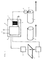
Figur 1 stellt grob schematisch den Ablauf des erfindungsgemässen Verfahrens beim Schweissen von Dosenzargen dar. Beim Schweissen von Dosenzargen wird ein ebener Blechabschnitt 1 in einem Rundapparat zu einer Zarge 2 verformt. Die verformte Zarge, welche in der Regel eine Ueberlappung aufweist, die in einer Rollnahtwiderstandschweissmaschine zu einer Ueberlappungsnaht geschweisst wird, ist in der Figur mit 3 bezeichnet. Zwischen der oberen Elektrode 4 und der unteren Elektrode 5 der Rollnahtwiderstandschweissmaschine wird die Naht geschweisst. In der Regel finden dabei Drahtelektroden Verwendung, welche auf den gezeigten Rollen 4 und 5 ablaufen, welche aber in der Figur nicht dargestellt sind. Der Schweissstrom für die Bildung der Schweissnaht wird von einer Schweissstromquelle 6 bereitgestellt. Diese umfasst einen Schweisstransformator und einen Treiber 8 für den Schweisstransformator, welcher aus der Speisepannung U eine Primärspannung mit einer Frequenz von z.B. 500 Hz für den Schweisstransformator bereitstellt. Ueblicherweise wird dabei über eine Stromrückführung von der Sekundärseite des Transformators 7 zum Treiber 8, der einen entsprechenden Regler enthält, ein konstanter Schweissstrom I bewirkt. Der konstante Schweissstrom I ergibt aber bei einer Beschichtung der Bleche 1 mit einer von Blech zu Blech schwankenden oder innerhalb eines Bleches schwankenden Dicke eine schwankende Leistungseinbringung in den Schweissnahtbereich und damit eine ungleichmässige Schweissqualität. Gemäss der Erfindung wird nun vorgesehen, dass die Beschichtungsdicke der Beschichtung des Bleches 1 im Betrieb gemessen wird und dass der Schweissstrom entsprechend der Beschichtungsdicke variiert wird. Zu diesem Zweck ist in der schematischen Darstellung eine Messeinrichtung 11 dargestellt, welche beim Blech 1 die Schichtdicke der Beschichtung misst. Das entsprechende Resultat wird an die Schweisstromquelle 6 abgegeben, welche den Schweissstrom entsprechend der gemessenen Schichtdicke einstellt, wenn das zugehörige Blech 1 im Bereich der Schweissrollen 4 und 5 angekommen ist. Die Schichtdicke kann dabei nur auf einer Seite des Bleches mit der Messeinrichtung 11 bestimmt werden. Es kann auch eine weitere Messeinrichtung 12 auf der anderen Seite des Bleches vorgesehen sein, um auch dort die Beschichtungsdicke zu messen. Bei den Blechen kann es sich um verschiedenste Arten von beschichteten Blechen handeln. Beim gezeigten Anwendungsfall des Schweissens von Dosenzargen, wird es sich in der Regel um Weissblech handeln, d.h. Stahlblech, welches in der Regel beidseitig mit einer Zinnschicht versehen ist. Die Messung der Schichtdicke erfolgt dabei vorzugsweise in demjenigen Bereich des Bleches, der nach der Rundung zur Dosenzarge den Schweissnahtbereich bildet. Anstelle der Messung am ebenen Blech kann natürlich auch eine Schichtdickenbestimmung beim schon gerundeten Blech erfolgen.FIG. 1 shows a rough schematic of the sequence of the method according to the invention when welding can bodies. When welding can bodies, a flat
Die Schweissstromquelle 6 wird zur Durchführung des Verfahrens mit mindestens einem Eingang versehen, an welchem das Messresultat der Dickenmesseinrichtung 11 angelegt werden kann. Dieses Resultat wird dann dazu benutzt, den Schweissstrom entsprechend der gemessenen Dicke zu variieren, bzw. der gemessenen Dicke jeweils einen Schweissstromsollwert I zuzuordnen, welcher dann von der Schweissstromquelle eingehalten wird. Sofern eine zweite Dickenmesseinrichtung 12 vorgesehen ist, wird auch deren Signal zur Steuerung herangezogen bzw. dieses Signal wird mit dem Signal der ersten Dickenmesseinrichtung 11 verknüpft. Vorzugsweise erfolgt die Messung der Dicke kontinuierlich oder mit einer Vielzahl von Messpunkten für jedes Blech und die Anpassung des Schweissstromes I erfolgt so rasch, dass Beschichtungsdickenschwankungen innerhalb der selben Dosenzarge bzw. des selben Bleches durch Aenderung des Schweissstromes kompensiert werden können. Der Strom kann aber auch nur für jedes Blech aufgrund einer oder mehrerer Messungen der Schichtdicke an diesem Blech auf einen für den ganzen Schweissvorgang an diesem Blech gültigen Wert festgelegt werden, so dass der Stromwert innerhalb der Schweissnaht nicht geändert wird. Auf diese Weise kann mit Blechen, die innerhalb jedes Bleches eine im wesentlichen gleichmässige Beschichtung besitzen, die aber von Blech zu Blech eine unterschiedliche Beschichtung aufweisen, eine gleichmässige Schweissung erzielt werden. Häufig weisen Bleche aus dem Coil-Randbereich eine grössere Zinndicke auf als Bleche aus der Coil-Mitte. Die Mischung solcher Bleche 1 mit Blechen aus der Coil-Mitte ergibt bei herkömmlicher Schweissung im Bereich der dickeren Zinnschicht Kaltschweissungen, da der Kontaktwiderstand geringer ist. Mit dem Schweissverfahren gemäss den beiden genannten Varianten wird jedes Blech bzw. wird jede Zarge mit dem passenden Strom geschweisst, bzw. dieser Strom wird innerhalb der Zarge variiert, um eine optimale Schweissung zu gewährleisten.To carry out the method, the welding
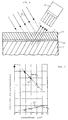
Figur 2 zeigt schematisch ein Beispiel zur Messung der Schichtdicke bei einem Weissblech 1. Dieses ist nur teilweise im Vertikalschnitt dargestellt und besteht aus einem Stahlblech 13, welches mindestens einseitig, aber in der Regel beidseitig mit einer Zinnschicht 15 versehen ist. Zwischen dem Stahlblech und der Zinnschicht ist eine Eisen-Zinn-Zwischenschicht 14 gebildet. Bei der Bestrahlung der Blechoberfläche des Bleches 1 mit energiereichen elektromagnetischen Wellen (Röntgen- oder Gammastrahlen) wird eine Eigenstrahlung des Stahls und der Zinnschicht angeregt. In der Figur 2 ist die Gammastrahlung als Strahlung 16 angedeutet. Die Eigenstrahlung des Stahls und des Zinns wird als Strahlung 17 dargestellt, die von einem Strahlungsempfänger 18 aufgefangen wird und ausgewertet wird. Das Auswerteergebnis wird, wie in Figur 1 gezeigt, an die Schweissstromquelle abgegeben. Solche Messeinrichtungen sind an sich bekannt und werden von den Herstellern beschichteter Bleche auch zur Steuerung und Ueberwachung der Zinnauflage eingesetzt. Zur Messung der Zinnschicht auf Stahl wird meistens die energiereiche Eisen-K-Alphastrahlung als Eigenstrahlung 17 herangezogen, welche durch Schichtdickenschwankungen des Zinns in unterschiedlicher, aber bestimmter Weise geschwächt wird, so dass die Schwächung der Eisen-K-Alphastrahlung durch die Zinnschicht ein Mass für deren Schichtdicke darstellt.FIG. 2 schematically shows an example for measuring the layer thickness in the case of
Figur 3 zeigt schematisch in einem Diagramm die Intensität der Eigenstrahlung sowohl für die Eisen-K-Alphastrahlung 20 als auch für die Zinn-K-Alphastrahlung in Abhängigkeit von der Stärke der Zinnauflage auf dem Blech. Es ist daraus ersichtlich, dass durch Messung der Intensität der Eigenstrahlung 20 die Zinnauflage genau bestimmt werden kann.FIG. 3 shows schematically in a diagram the intensity of the natural radiation both for the iron-
Anstelle der Messung der Beschichtungsdicke durch ein Strahlungsmesssystem können natürlich auch andere Messverfahren verwendet werden. So kann die Dicke einer Beschichtung über magnetische oder elektrische Parameter des beschichteten Bleches ermittelt werden. Das jeweils geeignete Verfahren kann aus den für die jeweilige Beschichtung geeigneten bekannten Verfahren ausgewählt werden.Instead of measuring the coating thickness by means of a radiation measurement system, other measurement methods can of course also be used. In this way, the thickness of a coating can be determined using magnetic or electrical parameters of the coated sheet. The most suitable method can be selected from the known methods suitable for the respective coating.
Claims (8)
Applications Claiming Priority (3)
| Application Number | Priority Date | Filing Date | Title |
|---|---|---|---|
| CH229195 | 1995-08-09 | ||
| CH2291/95 | 1995-08-09 | ||
| CH229195 | 1995-08-09 |
Publications (2)
| Publication Number | Publication Date |
|---|---|
| EP0761368A1 true EP0761368A1 (en) | 1997-03-12 |
| EP0761368B1 EP0761368B1 (en) | 2000-02-02 |
Family
ID=4230347
Family Applications (1)
| Application Number | Title | Priority Date | Filing Date |
|---|---|---|---|
| EP96110970A Expired - Lifetime EP0761368B1 (en) | 1995-08-09 | 1996-07-08 | Welding method for coated sheets, especially tin-plated sheets |
Country Status (9)
| Country | Link |
|---|---|
| US (1) | US5841094A (en) |
| EP (1) | EP0761368B1 (en) |
| JP (1) | JP2755938B2 (en) |
| KR (1) | KR970009965A (en) |
| CN (1) | CN1082862C (en) |
| BR (1) | BR9603348A (en) |
| DE (1) | DE59604358D1 (en) |
| RU (1) | RU2162396C2 (en) |
| TW (1) | TW310289B (en) |
Cited By (3)
| Publication number | Priority date | Publication date | Assignee | Title |
|---|---|---|---|---|
| EP2110196A2 (en) * | 2008-04-17 | 2009-10-21 | Soudronic AG | Method and welding device for determining the welding electric current to be applied during welding of can bodies |
| EP2243584A1 (en) | 2009-04-22 | 2010-10-27 | Soudronic AG | Method and device for manufacturing container frames from such sheet metal |
| CN103630094A (en) * | 2013-01-21 | 2014-03-12 | 中电投工程研究检测评定中心 | Online thickness detection method for chromium-free film at surface of strip steel |
Families Citing this family (18)
| Publication number | Priority date | Publication date | Assignee | Title |
|---|---|---|---|---|
| ATE348679T1 (en) * | 2000-07-27 | 2007-01-15 | Elpatronic Ag | METHOD AND WELDING DEVICE FOR WELDING SHEET METAL OVERLAPS |
| EP1663562B1 (en) * | 2003-09-16 | 2011-06-15 | Soudronic AG | Can welding machine with powder monitor |
| DE202005021631U1 (en) | 2004-12-27 | 2009-01-08 | Zens, Joachim | Apparatus for seam welding a workpiece |
| JP4505491B2 (en) * | 2007-11-05 | 2010-07-21 | 新日本製鐵株式会社 | Apparatus and method for heating welded portion of steel pipe |
| JP4600873B2 (en) * | 2008-02-20 | 2010-12-22 | 株式会社ホンダアクセス | Method for manufacturing painted metal parts using welding |
| ES2423938T3 (en) * | 2008-05-14 | 2013-09-25 | Soudronic Ag | Method for marking sheet metal and welding dependent on the marking of container bodies of such sheet material |
| EP2322308A4 (en) * | 2008-07-11 | 2014-06-11 | Mitsubishi Hitachi Metals | Mash seam welding method and equipment |
| CH701448B1 (en) * | 2009-07-02 | 2022-07-29 | Soudronic Ag | Process and welding device for assessing the welding current strength used in resistance seam welding of container bodies. |
| CH707161A1 (en) * | 2012-11-06 | 2014-05-15 | Soudronic Ag | Method and Apparatus for the seam welding of container bodies. |
| CH707362B1 (en) * | 2012-12-17 | 2019-05-15 | Soudronic Ag | Method for destacking metal sheets and stacking device. |
| CN103252556A (en) * | 2013-04-25 | 2013-08-21 | 吴江市云通钢桶机械厂 | Seam welding method with welding directly achieved by galvanized steel plate and hot dip galvanizing coating not damaged |
| CN104677852A (en) * | 2013-11-27 | 2015-06-03 | 上海宝钢工业技术服务有限公司 | Strip steel magnesium oxide coating quality online detection system |
| RU2553314C1 (en) * | 2014-01-09 | 2015-06-10 | Федеральное государственное бюджетное образовательное учреждение высшего профессионального образования "Липецкий государственный технический университет" (ЛГТУ) | Method of electric contact welding of metal plates with coating |
| US20150343507A1 (en) * | 2014-05-28 | 2015-12-03 | Taylor-Winfield Technologies, Inc. | Barrel tank seam welder system |
| US20180001370A1 (en) | 2014-05-28 | 2018-01-04 | Taylor-Winfield Technologies, Inc. | Barrel tank seam welder system |
| EP3028836B1 (en) * | 2014-12-04 | 2017-11-01 | Leister Technologies AG | Welding machine for connecting of overlapping sheets of material |
| CN107457475A (en) * | 2017-07-24 | 2017-12-12 | 南昌大学 | The coating unit and method of metal surface wear-resistant coating |
| JP7027122B2 (en) * | 2017-10-27 | 2022-03-01 | シロキ工業株式会社 | How to seam weld vehicle door sashes |
Citations (6)
| Publication number | Priority date | Publication date | Assignee | Title |
|---|---|---|---|---|
| US3610862A (en) * | 1969-01-31 | 1971-10-05 | Continental Can Co | Method and apparatus for resistance welding utilizing application of high pressure |
| US4160892A (en) * | 1975-03-19 | 1979-07-10 | Paul Opprecht | Method and apparatus for seam welding overlapped edges |
| JPS5665995A (en) * | 1979-10-31 | 1981-06-04 | Kawasaki Steel Corp | Production of tin-plated steel plate of high work efficiency |
| GB2178682A (en) * | 1983-06-10 | 1987-02-18 | Nippon Kokan Kk | Electric-resistance seam-welding method |
| EP0547322A1 (en) * | 1991-12-16 | 1993-06-23 | Elpatronic Ag | Method for monitoring the welding quality during resistance seam-squeeze welding |
| EP0622148A1 (en) * | 1993-04-27 | 1994-11-02 | Sollac S.A. | Resistance welding current control method and apparatus |
Family Cites Families (3)
| Publication number | Priority date | Publication date | Assignee | Title |
|---|---|---|---|---|
| DE3161098D1 (en) * | 1980-04-22 | 1983-11-10 | Toyo Seikan Kaisha Ltd | Method of manufacturing a welded can body |
| FR2553320B1 (en) * | 1983-10-14 | 1986-02-21 | Carnaud Sa | METHOD OF WELDING THE BODY OF CYLINDRICAL PACKAGING, OF THE BOX TYPE CONTAINER IN A MATERIAL COMPRISING ON AT LEAST ONE OF THE SIDES OF A SHEET A CONDUCTIVE COATING OF SPECIFIC CONTACT RESISTANCE SUPERIOR TO 1 X 10⁻⁵ OHM / CM2 |
| JPS61206576A (en) * | 1985-03-11 | 1986-09-12 | Nepiyuu Giken:Kk | Welding method of lap joint of can body made of metallic plate and the like |
-
1996
- 1996-07-08 EP EP96110970A patent/EP0761368B1/en not_active Expired - Lifetime
- 1996-07-08 DE DE59604358T patent/DE59604358D1/en not_active Expired - Fee Related
- 1996-07-26 TW TW085109133A patent/TW310289B/zh active
- 1996-07-29 KR KR1019960030944A patent/KR970009965A/en active IP Right Grant
- 1996-07-30 JP JP8200250A patent/JP2755938B2/en not_active Expired - Fee Related
- 1996-08-02 US US08/692,011 patent/US5841094A/en not_active Expired - Fee Related
- 1996-08-08 BR BR9603348A patent/BR9603348A/en not_active IP Right Cessation
- 1996-08-09 RU RU96116143/02A patent/RU2162396C2/en not_active IP Right Cessation
- 1996-08-09 CN CN96112166A patent/CN1082862C/en not_active Expired - Fee Related
Patent Citations (8)
| Publication number | Priority date | Publication date | Assignee | Title |
|---|---|---|---|---|
| US3610862A (en) * | 1969-01-31 | 1971-10-05 | Continental Can Co | Method and apparatus for resistance welding utilizing application of high pressure |
| US4160892A (en) * | 1975-03-19 | 1979-07-10 | Paul Opprecht | Method and apparatus for seam welding overlapped edges |
| US4160892B1 (en) * | 1975-03-19 | 1984-06-05 | ||
| US4160892B2 (en) * | 1975-03-19 | 1988-06-28 | Method and apparatus for seam welding overlapped edges | |
| JPS5665995A (en) * | 1979-10-31 | 1981-06-04 | Kawasaki Steel Corp | Production of tin-plated steel plate of high work efficiency |
| GB2178682A (en) * | 1983-06-10 | 1987-02-18 | Nippon Kokan Kk | Electric-resistance seam-welding method |
| EP0547322A1 (en) * | 1991-12-16 | 1993-06-23 | Elpatronic Ag | Method for monitoring the welding quality during resistance seam-squeeze welding |
| EP0622148A1 (en) * | 1993-04-27 | 1994-11-02 | Sollac S.A. | Resistance welding current control method and apparatus |
Non-Patent Citations (1)
| Title |
|---|
| PATENT ABSTRACTS OF JAPAN vol. 005, no. 132 (C - 068) 22 August 1981 (1981-08-22) * |
Cited By (9)
| Publication number | Priority date | Publication date | Assignee | Title |
|---|---|---|---|---|
| EP2110196A2 (en) * | 2008-04-17 | 2009-10-21 | Soudronic AG | Method and welding device for determining the welding electric current to be applied during welding of can bodies |
| EP2110197A2 (en) * | 2008-04-17 | 2009-10-21 | Soudronic AG | Method and welding device for determining the welding electric current to be applied during welding of can bodies |
| EP2110196A3 (en) * | 2008-04-17 | 2011-01-26 | Soudronic AG | Method and welding device for determining the welding electric current to be applied during welding of can bodies |
| EP2110197A3 (en) * | 2008-04-17 | 2011-02-16 | Soudronic AG | Method and welding device for determining the welding electric current to be applied during welding of can bodies |
| US9085044B2 (en) | 2008-04-17 | 2015-07-21 | Soudronic Ag | Method and welding apparatus for the determination of the strength of the welding current to be used in the welding of container bodies |
| US10022814B2 (en) | 2008-04-17 | 2018-07-17 | Soudronic Ag | Method and welding apparatus for the determination of the strength of the welding current to be used in the welding of container bodies |
| EP2243584A1 (en) | 2009-04-22 | 2010-10-27 | Soudronic AG | Method and device for manufacturing container frames from such sheet metal |
| US9505077B2 (en) | 2009-04-22 | 2016-11-29 | Soudronic Ag | Method for manufacturing container bodies from metal sheet |
| CN103630094A (en) * | 2013-01-21 | 2014-03-12 | 中电投工程研究检测评定中心 | Online thickness detection method for chromium-free film at surface of strip steel |
Also Published As
| Publication number | Publication date |
|---|---|
| EP0761368B1 (en) | 2000-02-02 |
| RU2162396C2 (en) | 2001-01-27 |
| DE59604358D1 (en) | 2000-03-09 |
| CN1151924A (en) | 1997-06-18 |
| CN1082862C (en) | 2002-04-17 |
| KR970009965A (en) | 1997-03-27 |
| JPH09103886A (en) | 1997-04-22 |
| TW310289B (en) | 1997-07-11 |
| JP2755938B2 (en) | 1998-05-25 |
| BR9603348A (en) | 1998-05-05 |
| US5841094A (en) | 1998-11-24 |
Similar Documents
| Publication | Publication Date | Title |
|---|---|---|
| EP0761368B1 (en) | Welding method for coated sheets, especially tin-plated sheets | |
| EP0373422B1 (en) | Apparatus for monitoring quality of electrical welding processes | |
| DE2004688C3 (en) | Automatic control for plasma welding equipment | |
| DE2532976A1 (en) | PROCESS FOR SEMI-AUTOMATIC OR FULLY AUTOMATIC SEAM WELDING OF PLATES AND RESISTANCE WELDING MACHINE FOR PERFORMING THE PROCESS | |
| CH701448B1 (en) | Process and welding device for assessing the welding current strength used in resistance seam welding of container bodies. | |
| DE102012214843A1 (en) | Welding plan for resistance spot welding of aluminum alloy workpieces | |
| DE3711771C2 (en) | ||
| EP1249298B1 (en) | Method and apparatus for assessing the quality of and control and monitor pressure welding and fusion welding processes | |
| WO2012116847A1 (en) | Method for enhancing a metallic coating on a steel strip | |
| DE2703113C3 (en) | Method and device for regulating the power of an arc welding torch | |
| DE2010878C3 (en) | Method for monitoring a resistance point welding process | |
| DE2634341A1 (en) | METHOD AND EQUIPMENT FOR ALIGNING A CARGO CARRIER JET OF A TECHNICAL CARGO CARRIAGE BLAST DEVICE | |
| DE1905770C3 (en) | Device for build-up welding on metallic workpieces using a direct current arc | |
| DE3134346C2 (en) | ||
| DE3635946A1 (en) | METHOD AND DEVICE FOR WELDING | |
| EP4010517A1 (en) | Method and system for electroytically coating a steel strip by means of pulse technology | |
| DE2507053A1 (en) | METHOD AND DEVICE FOR ELECTROEROSION MACHINING | |
| EP2110197B1 (en) | Method and welding device for determining the welding electric current to be applied during welding of can bodies | |
| EP0132575A1 (en) | Device for arc welding, particularly for submerged arc welding with one or two consumable electrodes | |
| DE4203190C1 (en) | Regulation and quality assessing of welding esp. spot welding - has ultrasonic detecting probe attached to welding electrode to record noise emission level at weld location | |
| DE102011018653A1 (en) | Resistance-welding apparatus comprises first main electrode and second main electrode for introducing welding current into workpiece to be welded, where one of the main electrodes is a part of an electrode arrangement, and adjusting unit | |
| DE670741C (en) | Method and device for colon or seam welding | |
| DE102004054856B4 (en) | Metal sheet quality control, by measurements of electrical resistance, reads the resistance from two electrodes at the surfaces and also after a defined change of the surface characteristics | |
| DE10215454C1 (en) | Process for regulating the current source of electrical resistance welding device, comprises the energy or electrical amount introduced during several, preferably all impulses and controlling the switching duration of the impulses | |
| DE4409186C2 (en) | Method for controlling the welding current in a DC resistance welding machine |
Legal Events
| Date | Code | Title | Description |
|---|---|---|---|
| PUAI | Public reference made under article 153(3) epc to a published international application that has entered the european phase |
Free format text: ORIGINAL CODE: 0009012 |
|
| AK | Designated contracting states |
Kind code of ref document: A1 Designated state(s): CH DE GB IT LI NL |
|
| 17P | Request for examination filed |
Effective date: 19970912 |
|
| RAP3 | Party data changed (applicant data changed or rights of an application transferred) |
Owner name: ELPATRONIC AG |
|
| GRAG | Despatch of communication of intention to grant |
Free format text: ORIGINAL CODE: EPIDOS AGRA |
|
| GRAG | Despatch of communication of intention to grant |
Free format text: ORIGINAL CODE: EPIDOS AGRA |
|
| GRAH | Despatch of communication of intention to grant a patent |
Free format text: ORIGINAL CODE: EPIDOS IGRA |
|
| 17Q | First examination report despatched |
Effective date: 19990623 |
|
| GRAH | Despatch of communication of intention to grant a patent |
Free format text: ORIGINAL CODE: EPIDOS IGRA |
|
| GRAA | (expected) grant |
Free format text: ORIGINAL CODE: 0009210 |
|
| AK | Designated contracting states |
Kind code of ref document: B1 Designated state(s): CH DE GB IT LI NL |
|
| REG | Reference to a national code |
Ref country code: CH Ref legal event code: EP |
|
| REF | Corresponds to: |
Ref document number: 59604358 Country of ref document: DE Date of ref document: 20000309 |
|
| ITF | It: translation for a ep patent filed |
Owner name: DE DOMINICIS & MAYER S.R.L. |
|
| GBT | Gb: translation of ep patent filed (gb section 77(6)(a)/1977) |
Effective date: 20000321 |
|
| PLBE | No opposition filed within time limit |
Free format text: ORIGINAL CODE: 0009261 |
|
| STAA | Information on the status of an ep patent application or granted ep patent |
Free format text: STATUS: NO OPPOSITION FILED WITHIN TIME LIMIT |
|
| 26N | No opposition filed | ||
| REG | Reference to a national code |
Ref country code: GB Ref legal event code: IF02 |
|
| PGFP | Annual fee paid to national office [announced via postgrant information from national office to epo] |
Ref country code: GB Payment date: 20040628 Year of fee payment: 9 |
|
| PGFP | Annual fee paid to national office [announced via postgrant information from national office to epo] |
Ref country code: CH Payment date: 20040702 Year of fee payment: 9 |
|
| PGFP | Annual fee paid to national office [announced via postgrant information from national office to epo] |
Ref country code: NL Payment date: 20040708 Year of fee payment: 9 |
|
| PGFP | Annual fee paid to national office [announced via postgrant information from national office to epo] |
Ref country code: DE Payment date: 20040727 Year of fee payment: 9 |
|
| PG25 | Lapsed in a contracting state [announced via postgrant information from national office to epo] |
Ref country code: IT Free format text: LAPSE BECAUSE OF NON-PAYMENT OF DUE FEES;WARNING: LAPSES OF ITALIAN PATENTS WITH EFFECTIVE DATE BEFORE 2007 MAY HAVE OCCURRED AT ANY TIME BEFORE 2007. THE CORRECT EFFECTIVE DATE MAY BE DIFFERENT FROM THE ONE RECORDED. Effective date: 20050708 Ref country code: GB Free format text: LAPSE BECAUSE OF NON-PAYMENT OF DUE FEES Effective date: 20050708 |
|
| PG25 | Lapsed in a contracting state [announced via postgrant information from national office to epo] |
Ref country code: LI Free format text: LAPSE BECAUSE OF NON-PAYMENT OF DUE FEES Effective date: 20050731 Ref country code: CH Free format text: LAPSE BECAUSE OF NON-PAYMENT OF DUE FEES Effective date: 20050731 |
|
| PG25 | Lapsed in a contracting state [announced via postgrant information from national office to epo] |
Ref country code: NL Free format text: LAPSE BECAUSE OF NON-PAYMENT OF DUE FEES Effective date: 20060201 Ref country code: DE Free format text: LAPSE BECAUSE OF NON-PAYMENT OF DUE FEES Effective date: 20060201 |
|
| REG | Reference to a national code |
Ref country code: CH Ref legal event code: PL |
|
| GBPC | Gb: european patent ceased through non-payment of renewal fee |
Effective date: 20050708 |
|
| NLV4 | Nl: lapsed or anulled due to non-payment of the annual fee |
Effective date: 20060201 |