EP0760558A1 - D-Flip-Flop mit asynchronem Laden von Daten - Google Patents
D-Flip-Flop mit asynchronem Laden von Daten Download PDFInfo
- Publication number
- EP0760558A1 EP0760558A1 EP95830370A EP95830370A EP0760558A1 EP 0760558 A1 EP0760558 A1 EP 0760558A1 EP 95830370 A EP95830370 A EP 95830370A EP 95830370 A EP95830370 A EP 95830370A EP 0760558 A1 EP0760558 A1 EP 0760558A1
- Authority
- EP
- European Patent Office
- Prior art keywords
- input
- circuit
- input terminal
- logic
- signals
- Prior art date
- Legal status (The legal status is an assumption and is not a legal conclusion. Google has not performed a legal analysis and makes no representation as to the accuracy of the status listed.)
- Granted
Links
Images

Classifications
-
- H—ELECTRICITY
- H03—ELECTRONIC CIRCUITRY
- H03K—PULSE TECHNIQUE
- H03K3/00—Circuits for generating electric pulses; Monostable, bistable or multistable circuits
- H03K3/02—Generators characterised by the type of circuit or by the means used for producing pulses
- H03K3/027—Generators characterised by the type of circuit or by the means used for producing pulses by the use of logic circuits, with internal or external positive feedback
- H03K3/037—Bistable circuits
- H03K3/0372—Bistable circuits of the master-slave type
-
- H—ELECTRICITY
- H03—ELECTRONIC CIRCUITRY
- H03K—PULSE TECHNIQUE
- H03K3/00—Circuits for generating electric pulses; Monostable, bistable or multistable circuits
- H03K3/02—Generators characterised by the type of circuit or by the means used for producing pulses
- H03K3/353—Generators characterised by the type of circuit or by the means used for producing pulses by the use, as active elements, of field-effect transistors with internal or external positive feedback
- H03K3/356—Bistable circuits
- H03K3/3562—Bistable circuits of the master-slave type
- H03K3/35625—Bistable circuits of the master-slave type using complementary field-effect transistors
Definitions
- This invention relates to logic networks of the sequential type, and particularly to bistable circuits -- more commonly referred to as flip-flops in the pertinent literature -- of the D type, conventionally comprised of two cascaded bistable circuits, namely a master and a slave circuit.
- Flip-flops of the D type are used to provide a delay in the transmission of data; the propagation of such data from the master section to the slave section only being allowed on the occurrence of a given clock signal.
- Examples of such applications are the parallel-to-serial converter and the counter with asynchronous data preloading.
- a prior technical solution consists of adding a suitable external logic to a D-type flip-flop having "preset” and “set” capabilities, e.g. as in the counters sold under selling code HCC/HCF40192B by this Applicant.
- a flip-flop of the D type is proposed therein which inherently performs the asynchronous data storage function. Accordingly, the storage element can be a compact one requiring less area of integration on the silicon and effectively avoiding possible problems from the presence of a complementary external logic.
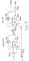
- FIG. 1 of the drawings Shown in Figure 1 of the drawings is a circuit diagram for such a flip-flop which directly permits of asynchronous data loading.
- the technical problem underlying this invention is to provide a flip-flop of the D type which also performs the asynchronous data loading function and affords improved control capabilities over prior solutions.
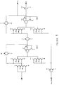
- FIG. 2 Shown in Figure 2 is a circuit diagram of a flip-flop of the D type, according to the invention, which uses a master/slave configuration for data storage. It therefore comprises a first (master) flip-flop for storing the input data and a second (slave) flip-flop supplying the output signal.
- Both flip-flops include transmission gating inputs TGI1 and TGI2, respectively, and interface and selection circuits MUX1 and MUX2, respectively, each having a first input terminal connected to a respective transmission gating input.
- the two flip-flops further include respective logic gates ND1 and ND2, of the NAND type as shown in the Figure, each having an input terminal connected to the output terminal of the respective interface and selection circuit, the latter being in the form of a multiplexer consisting, for example, of a double buffer tristate with an inverting output and having an output terminal which forms an output terminal of the respective flip-flop.
- each of the two logic gates has an input terminal CLEAR which allows the flip-flop comprising it to be driven to a predetermined state by a special active signal, which may be a simple pulse.
- a transmission gate TG1 and TG2 is negative feedback-connected between the output terminal of the flip-flop and the first input terminal of the interface and selection circuit.
- each of the two interface and selection circuits MUX1 and MUX2 Connected to a second input terminal of each of the two interface and selection circuits MUX1 and MUX2, through a common inverter circuit INV1, is an asynchronous data input terminal AS_DATA.
- a second output terminal Q of the D-type flip-flop is provided, additionally to that formed directly by the output terminal NQ of the slave flip-flop, by connecting an inverter circuit INV2 to a circuit node thereof.
- the transmission gating input TGI1 of the master flip-flop is of the inverting type, in order to regenerate the signal applied to the input terminal D of the D-type flip-flop.
- the transmission gating input TGI1 can be a buffer tristate with a high-impedance separating and uncoupling function.
- All the transmission gates and interface/selection circuits are driven by clock signals.
- the clock signal is split into two signals fi and Nfi; fi being in phase with the clock, and Nfi in phase opposition therewith.
- the asynchronous load signal is split into ld and Nld (the loading becoming active on the high logic level).
- the operation of the flip-flop in the instance of a positive edge triggered clock signal will be considered.
- the negative edge triggering function is obtained by exchanging Nfi for fi. It is likewise possible to obtain the asynchronous data loading on a different logic level from that under consideration by exchanging Nld for ld.
- a master/slave flip-flop when a master/slave flip-flop must be allowed to have asynchronous direct inputs, these should be connected to both the master and the slave, so as to "bypass" the clock signal (fi, Nfi).
- the load signal enables storage, into both the master and slave flip-flops, of the data which appears asynchronously at the input AS_DATA.
- the flip-flop When the load signal is at its logic low, the flip-flop operates normally as a positive edge triggered D.
- the multiplexers formed by the gates TI1-TI2 and TI3-TI4 will carry to the nodes P and N the logic value present at the input AS_DATA.
- the asynchronous input is left unheeded upon the signal ld being restored to its logic low; in this case, the asynchronous data is still held at the output by one of the two feedback loops of the master and the slave, according to the value of fi.
- the master and slave inputs become active once again, so that the new data will be sampled at the first useful edge of the clock signal.
- circuit arrangement including the two logic gates ND1 and ND2 allows the low logic level to be forced asynchronously out by the application of a special low active signal to the terminals CLEAR of the gates.
- Inverters may be placed on the outputs Q and NQ of the flip-flop in order to output regenerated signals having high driving capabilities.
Landscapes
- Logic Circuits (AREA)
Priority Applications (3)
| Application Number | Priority Date | Filing Date | Title |
|---|---|---|---|
| DE69514918T DE69514918T2 (de) | 1995-08-31 | 1995-08-31 | D-Flip-Flop mit asynchronem Laden von Daten |
| EP95830370A EP0760558B1 (de) | 1995-08-31 | 1995-08-31 | D-Flip-Flop mit asynchronem Laden von Daten |
| US08/706,407 US5789957A (en) | 1995-08-31 | 1996-08-30 | D flip-flop having asynchronous data loading |
Applications Claiming Priority (1)
| Application Number | Priority Date | Filing Date | Title |
|---|---|---|---|
| EP95830370A EP0760558B1 (de) | 1995-08-31 | 1995-08-31 | D-Flip-Flop mit asynchronem Laden von Daten |
Publications (2)
| Publication Number | Publication Date |
|---|---|
| EP0760558A1 true EP0760558A1 (de) | 1997-03-05 |
| EP0760558B1 EP0760558B1 (de) | 2000-02-02 |
Family
ID=8222007
Family Applications (1)
| Application Number | Title | Priority Date | Filing Date |
|---|---|---|---|
| EP95830370A Expired - Lifetime EP0760558B1 (de) | 1995-08-31 | 1995-08-31 | D-Flip-Flop mit asynchronem Laden von Daten |
Country Status (3)
| Country | Link |
|---|---|
| US (1) | US5789957A (de) |
| EP (1) | EP0760558B1 (de) |
| DE (1) | DE69514918T2 (de) |
Cited By (1)
| Publication number | Priority date | Publication date | Assignee | Title |
|---|---|---|---|---|
| WO2000076071A1 (de) * | 1999-06-07 | 2000-12-14 | Infineon Technologies Ag | Flipflop-schaltungsanordnung |
Families Citing this family (7)
| Publication number | Priority date | Publication date | Assignee | Title |
|---|---|---|---|---|
| US6229750B1 (en) | 1999-09-30 | 2001-05-08 | International Business Machines Corporation | Method and system for reducing power dissipation in a semiconductor storage device |
| JP2001237675A (ja) * | 2000-02-24 | 2001-08-31 | Ando Electric Co Ltd | D−ff回路 |
| US6557161B2 (en) * | 2001-06-28 | 2003-04-29 | Sun Microsystems, Inc. | Method for prototyping asynchronous circuits using synchronous devices |
| US6573775B2 (en) | 2001-10-30 | 2003-06-03 | Integrated Device Technology, Inc. | Integrated circuit flip-flops that utilize master and slave latched sense amplifiers |
| US6700425B1 (en) | 2001-10-30 | 2004-03-02 | Integrated Device Technology, Inc. | Multi-phase clock generators that utilize differential signals to achieve reduced setup and hold times |
| US7256633B1 (en) * | 2003-05-01 | 2007-08-14 | Ample Communications, Inc. | Systems for implementing high speed and high integration chips |
| RU2693321C1 (ru) * | 2018-11-21 | 2019-07-02 | Федеральное государственное учреждение "Федеральный исследовательский центр "Информатика и управление" Российской академии наук" (ФИЦ ИУ РАН) | Самосинхронный динамический двухтактный d-триггер с нулевым спейсером |
Citations (3)
| Publication number | Priority date | Publication date | Assignee | Title |
|---|---|---|---|---|
| US4970407A (en) | 1988-06-09 | 1990-11-13 | National Semiconductor Corporation | Asynchronously loadable D-type flip-flop |
| EP0472426A2 (de) * | 1990-08-24 | 1992-02-26 | AT&T GLOBAL INFORMATION SOLUTIONS INTERNATIONAL INC. | CMOS-Flipflop-Schaltung |
| US5189315A (en) * | 1991-02-18 | 1993-02-23 | Nec Corp. | High-speed flip flop circuit with master latching circuit free from influence of slave latching circuit |
Family Cites Families (4)
| Publication number | Priority date | Publication date | Assignee | Title |
|---|---|---|---|---|
| JPS6179318A (ja) * | 1984-09-27 | 1986-04-22 | Fujitsu Ltd | フリツプフロツプ回路 |
| JP2567110B2 (ja) * | 1989-09-28 | 1996-12-25 | 日本電気アイシーマイコンシステム株式会社 | D型フリップフロップ回路 |
| JP2946658B2 (ja) * | 1990-06-29 | 1999-09-06 | 日本電気株式会社 | フリップフロップ回路 |
| JPH0520791A (ja) * | 1991-07-12 | 1993-01-29 | Shikoku Nippon Denki Software Kk | 磁気デイスク装置 |
-
1995
- 1995-08-31 DE DE69514918T patent/DE69514918T2/de not_active Expired - Fee Related
- 1995-08-31 EP EP95830370A patent/EP0760558B1/de not_active Expired - Lifetime
-
1996
- 1996-08-30 US US08/706,407 patent/US5789957A/en not_active Expired - Lifetime
Patent Citations (3)
| Publication number | Priority date | Publication date | Assignee | Title |
|---|---|---|---|---|
| US4970407A (en) | 1988-06-09 | 1990-11-13 | National Semiconductor Corporation | Asynchronously loadable D-type flip-flop |
| EP0472426A2 (de) * | 1990-08-24 | 1992-02-26 | AT&T GLOBAL INFORMATION SOLUTIONS INTERNATIONAL INC. | CMOS-Flipflop-Schaltung |
| US5189315A (en) * | 1991-02-18 | 1993-02-23 | Nec Corp. | High-speed flip flop circuit with master latching circuit free from influence of slave latching circuit |
Cited By (2)
| Publication number | Priority date | Publication date | Assignee | Title |
|---|---|---|---|---|
| WO2000076071A1 (de) * | 1999-06-07 | 2000-12-14 | Infineon Technologies Ag | Flipflop-schaltungsanordnung |
| US6515528B1 (en) | 1999-06-07 | 2003-02-04 | Infineon Technologies Ag | Flip-flop circuit |
Also Published As
| Publication number | Publication date |
|---|---|
| US5789957A (en) | 1998-08-04 |
| DE69514918D1 (de) | 2000-03-09 |
| DE69514918T2 (de) | 2000-06-15 |
| EP0760558B1 (de) | 2000-02-02 |
Similar Documents
| Publication | Publication Date | Title |
|---|---|---|
| US6417711B2 (en) | High speed latch and flip-flop | |
| JP3587248B2 (ja) | スキャン用フリップフロップ | |
| US5489865A (en) | Circuit for filtering asynchronous metastability of cross-coupled logic gates | |
| US4970407A (en) | Asynchronously loadable D-type flip-flop | |
| US3609569A (en) | Logic system | |
| US5250858A (en) | Double-edge triggered memory device and system | |
| WO2001009900A2 (en) | High speed latch and flip-flop | |
| JP3645584B2 (ja) | データ転送同期装置 | |
| US5760612A (en) | Inertial delay circuit for eliminating glitches on a signal line | |
| EP0760558B1 (de) | D-Flip-Flop mit asynchronem Laden von Daten | |
| JP3130386B2 (ja) | フォーマッタ回路 | |
| US5148112A (en) | Efficient arbiter | |
| KR950012058B1 (ko) | 레지스터 제어 회로 | |
| US4569067A (en) | Dual master shift register bit | |
| US5187385A (en) | Latch circuit including filter for metastable prevention | |
| EP0496171B1 (de) | Bistabile integrierte Halbleiterschaltung | |
| EP0651319B1 (de) | System für Datentransfer | |
| US4090256A (en) | First-in-first-out register implemented with single rank storage elements | |
| US7383459B1 (en) | Apparatus and method for phase-buffering on a bit-by-bit basis using control queues | |
| JPS6179318A (ja) | フリツプフロツプ回路 | |
| US4928290A (en) | Circuit for stable synchronization of asynchronous data | |
| US4955041A (en) | Electronic pulse counter for simultaneous downward and upward counting | |
| US5912859A (en) | Method for the resetting of a shift register and associated register | |
| EP0330707A1 (de) | Verriegelungsschaltung | |
| US5249154A (en) | Data access controller and method |
Legal Events
| Date | Code | Title | Description |
|---|---|---|---|
| PUAI | Public reference made under article 153(3) epc to a published international application that has entered the european phase |
Free format text: ORIGINAL CODE: 0009012 |
|
| AK | Designated contracting states |
Kind code of ref document: A1 Designated state(s): DE FR GB IT |
|
| 17P | Request for examination filed |
Effective date: 19970825 |
|
| RAP3 | Party data changed (applicant data changed or rights of an application transferred) |
Owner name: STMICROELECTRONICS S.R.L. |
|
| GRAG | Despatch of communication of intention to grant |
Free format text: ORIGINAL CODE: EPIDOS AGRA |
|
| GRAG | Despatch of communication of intention to grant |
Free format text: ORIGINAL CODE: EPIDOS AGRA |
|
| GRAH | Despatch of communication of intention to grant a patent |
Free format text: ORIGINAL CODE: EPIDOS IGRA |
|
| 17Q | First examination report despatched |
Effective date: 19990723 |
|
| GRAH | Despatch of communication of intention to grant a patent |
Free format text: ORIGINAL CODE: EPIDOS IGRA |
|
| GRAA | (expected) grant |
Free format text: ORIGINAL CODE: 0009210 |
|
| AK | Designated contracting states |
Kind code of ref document: B1 Designated state(s): DE FR GB IT |
|
| ITF | It: translation for a ep patent filed |
Owner name: BOTTI & FERRARI S.R.L. |
|
| REF | Corresponds to: |
Ref document number: 69514918 Country of ref document: DE Date of ref document: 20000309 |
|
| ET | Fr: translation filed | ||
| PLBE | No opposition filed within time limit |
Free format text: ORIGINAL CODE: 0009261 |
|
| STAA | Information on the status of an ep patent application or granted ep patent |
Free format text: STATUS: NO OPPOSITION FILED WITHIN TIME LIMIT |
|
| 26N | No opposition filed | ||
| REG | Reference to a national code |
Ref country code: GB Ref legal event code: IF02 |
|
| PGFP | Annual fee paid to national office [announced via postgrant information from national office to epo] |
Ref country code: DE Payment date: 20040723 Year of fee payment: 10 |
|
| PG25 | Lapsed in a contracting state [announced via postgrant information from national office to epo] |
Ref country code: IT Free format text: LAPSE BECAUSE OF NON-PAYMENT OF DUE FEES;WARNING: LAPSES OF ITALIAN PATENTS WITH EFFECTIVE DATE BEFORE 2007 MAY HAVE OCCURRED AT ANY TIME BEFORE 2007. THE CORRECT EFFECTIVE DATE MAY BE DIFFERENT FROM THE ONE RECORDED. Effective date: 20050831 |
|
| PG25 | Lapsed in a contracting state [announced via postgrant information from national office to epo] |
Ref country code: DE Free format text: LAPSE BECAUSE OF NON-PAYMENT OF DUE FEES Effective date: 20060301 |
|
| PGFP | Annual fee paid to national office [announced via postgrant information from national office to epo] |
Ref country code: GB Payment date: 20060801 Year of fee payment: 12 |
|
| PGFP | Annual fee paid to national office [announced via postgrant information from national office to epo] |
Ref country code: FR Payment date: 20060831 Year of fee payment: 12 |
|
| GBPC | Gb: european patent ceased through non-payment of renewal fee |
Effective date: 20070831 |
|
| REG | Reference to a national code |
Ref country code: FR Ref legal event code: ST Effective date: 20080430 |
|
| PG25 | Lapsed in a contracting state [announced via postgrant information from national office to epo] |
Ref country code: FR Free format text: LAPSE BECAUSE OF NON-PAYMENT OF DUE FEES Effective date: 20070831 |
|
| PG25 | Lapsed in a contracting state [announced via postgrant information from national office to epo] |
Ref country code: GB Free format text: LAPSE BECAUSE OF NON-PAYMENT OF DUE FEES Effective date: 20070831 |