EP0760540A2 - Elektrischer Stecker mit verbessertem Verbinderpositioniermittel - Google Patents
Elektrischer Stecker mit verbessertem Verbinderpositioniermittel Download PDFInfo
- Publication number
- EP0760540A2 EP0760540A2 EP96113504A EP96113504A EP0760540A2 EP 0760540 A2 EP0760540 A2 EP 0760540A2 EP 96113504 A EP96113504 A EP 96113504A EP 96113504 A EP96113504 A EP 96113504A EP 0760540 A2 EP0760540 A2 EP 0760540A2
- Authority
- EP
- European Patent Office
- Prior art keywords
- terminal
- electrical connector
- elongated
- side wall
- pair
- Prior art date
- Legal status (The legal status is an assumption and is not a legal conclusion. Google has not performed a legal analysis and makes no representation as to the accuracy of the status listed.)
- Granted
Links
Images

Classifications
-
- H—ELECTRICITY
- H01—ELECTRIC ELEMENTS
- H01R—ELECTRICALLY-CONDUCTIVE CONNECTIONS; STRUCTURAL ASSOCIATIONS OF A PLURALITY OF MUTUALLY-INSULATED ELECTRICAL CONNECTING ELEMENTS; COUPLING DEVICES; CURRENT COLLECTORS
- H01R13/00—Details of coupling devices of the kinds covered by groups H01R12/70 or H01R24/00 - H01R33/00
- H01R13/40—Securing contact members in or to a base or case; Insulating of contact members
- H01R13/42—Securing in a demountable manner
- H01R13/428—Securing in a demountable manner by resilient locking means on the contact members; by locking means on resilient contact members
- H01R13/432—Securing in a demountable manner by resilient locking means on the contact members; by locking means on resilient contact members by stamped-out resilient tongue snapping behind shoulder in base or case
Definitions
- This invention generally relates to the art of electrical connectors and, particularly, to a positioning and stabilizing means or system for preventing relative movement of terminals in cavities of a connector housing.
- a wide variety of mating electrical connectors employ pairs of interengaging terminals for interconnecting a plurality of circuits or wires through the mated connectors.
- the pairs of terminals may be pin and socket terminals which often are called male and female terminals, respectively.
- the terminals are mounted in a plurality of terminal-receiving passageways or cavities in a dielectric housing of the electrical connector.
- the terminals generally are elongated and are inserted into the cavity along the longitudinal axes of the terminals.
- Some form of latch means normally are provided to hold the terminals in the cavities against withdrawal therefrom.
- the present invention is directed to solving the above stability problems with terminals in electrical connectors by providing a simple but effective positioning means or system between the terminals and the connector housing.
- An object, therefore, of the invention is to provide a new and improved terminal positioning means in an electrical connector.
- the connector is illustrated for connecting a conductor of an electrical wire to a terminal of a mating connector.
- the electrical connector includes a dielectric housing having at least one elongated terminal-receiving cavity defining a longitudinal axis. A terminal is received in the cavity, and the terminal has a mating portion adapted to mate with the terminal of the mating connector, a conductor-receiving portion, and an intermediate portion joining the mating and conductor-terminating portions.
- the intermediate portion includes a base and a pair of elongated resilient side walls extending from the base. Each side wall has an upper free end portion.
- the invention contemplates the provision of an elongated slot within a wall of the terminal-receiving cavity for receiving the upper free end portion of at least one of the side walls of the terminal to prevent movement of the terminal laterally or angularly of its longitudinal axis.
- a pair of the elongated slots are provided for receiving the upper free end portions of the pair of elongated resilient side walls of the terminal.
- the slots are laterally spaced apart, and the intermediate portion of the terminal is generally U-shaped as defined by the base and the pair of side walls.
- each side wall includes a bent portion offset laterally of the remainder of the side wall to provide a compliant fit within the respective elongated slot.
- the terminal is stamped and formed of sheet metal material, and the bent portion is sized and configured to provide the compliant fit in the slot.
- a latch portion of the terminal is formed out of each side wall between the respective bent portion thereof and the base of the terminal.
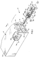
- Figures 1-3 show an electrical connector, generally designated 10, having a multi-cavity connector housing, generally designated 12, and incorporating the concepts of the invention.
- the housing is adapted for receiving a plurality of electrical terminals, generally designated 14, individually insertable into a respective one of a plurality of terminal-receiving cavities, generally designated 16, in housing 12.
- the housing is fabricated of dielectric material, such as being unitarily molded of plastic.
- the terminals are unitarily fabricated of stamped and formed conductive sheet metal material.
- FIG 1 is broken away to show that each terminal-receiving cavity has an interior transverse abutment face 18 spaced inwardly of the respective mouth 20 of each cavity.
- Each terminal 14 is inserted into its respective cavity 16 through the respective mouth 20 in the direction of arrow "A".
- Figure 4 shows that each terminal-receiving cavity 16 is formed with a pair of transversely spaced slots 22 which also can be seen in Figure 1. These slots run longitudinally of the cavity.
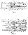
- each terminal 14 includes a mating portion 30 adapted to mate with the terminal of a mating connector (not shown) mateable with a forward mating end 32 of connector housing 12.
- mating portion 30 is formed as a terminal pin for insertion into a terminal socket of the mating connector.
- Each terminal 14 also has a conductor-terminating portion which is provided by two pairs of crimp arms 34 and 36.
- the pair of crimp arms 34 are adapted for clamping onto the conductor(s) 38 (Figs. 2 and 3) of an electrical wire, generally designated 40.
- the pair of crimp arms 36 are adapted for clamping onto the outer insulation 42 of the electrical wire.
- Each terminal 14 also includes an intermediate portion 44 joining mating portion 30 and conductor-terminating portion 34.
- the intermediate portion is generally U-shaped and includes a base wall 46 and a pair of upstanding side walls 48 extending from the base.
- Each side wall includes an upper free end portion 48a.
- a spring latch arm 50 is stamped out of each side wall 48 so as to be cantilevered angularly outwardly of the terminal. The latch arms are joined, as at 50a, to provide stiffness to the arms.
- a bent portion 52 is offset laterally outwardly of each side wall 48.
- a pair of stop arms 54 are bent generally perpendicularly outwardly of the terminal behind outwardly bent portions 52.
- each terminal 14 defines a longitudinal axis 56 coincident with a longitudinal axis of a respective one of the terminal-receiving cavities 16, with spring latch arms 50, outwardly bent portion 52 and stop arms 54 all extending or projecting transversely outwardly from side walls 48 laterally of axis 56.
- Figure 6 shows one of the terminals 14 inserted into its respective terminal-receiving cavity 16.
- Base wall 46 of the intermediate portion of the terminal seats on bottom wall 26 within housing 12 as described above in relation to Figure 1.
- outwardly cantilevered spring latch arms 50 snap into elongated side slots 24 behind a pair of latch shoulders 58 of the housing within the terminal-receiving cavity as shown clearly in Figure 3.
- stop arms 54 abut against transverse abutment face 18 within the cavity, as described above in relation to Figure 1. Therefore, in the fully inserted position of the terminal, the terminal is locked against forward or rearward movement by spring latch arms 50 and stop arms 54 as shown clearly in Figure 3.
Landscapes
- Connector Housings Or Holding Contact Members (AREA)
- Details Of Connecting Devices For Male And Female Coupling (AREA)
- Multi-Conductor Connections (AREA)
- Coupling Device And Connection With Printed Circuit (AREA)
Applications Claiming Priority (2)
| Application Number | Priority Date | Filing Date | Title |
|---|---|---|---|
| US518952 | 1983-08-01 | ||
| US08/518,952 US5664969A (en) | 1995-08-24 | 1995-08-24 | Electrical connector with improved terminal positioning means |
Publications (3)
| Publication Number | Publication Date |
|---|---|
| EP0760540A2 true EP0760540A2 (de) | 1997-03-05 |
| EP0760540A3 EP0760540A3 (de) | 1998-04-22 |
| EP0760540B1 EP0760540B1 (de) | 2001-07-25 |
Family
ID=24066175
Family Applications (1)
| Application Number | Title | Priority Date | Filing Date |
|---|---|---|---|
| EP96113504A Expired - Lifetime EP0760540B1 (de) | 1995-08-24 | 1996-08-22 | Elektrischer Stecker mit verbessertem Verbinderpositioniermittel |
Country Status (9)
| Country | Link |
|---|---|
| US (1) | US5664969A (de) |
| EP (1) | EP0760540B1 (de) |
| JP (1) | JP2934832B2 (de) |
| KR (1) | KR100231122B1 (de) |
| CN (1) | CN1107999C (de) |
| DE (1) | DE69614053T2 (de) |
| MY (1) | MY112661A (de) |
| SG (1) | SG66323A1 (de) |
| TW (1) | TW302564B (de) |
Cited By (3)
| Publication number | Priority date | Publication date | Assignee | Title |
|---|---|---|---|---|
| WO2009023117A1 (en) * | 2007-08-16 | 2009-02-19 | Tyco Electronics Corporation | Contacts for electrical connectors |
| CN106877047A (zh) * | 2017-04-10 | 2017-06-20 | 东莞市乔业电子有限公司 | 一种连接器 |
| WO2019086278A1 (de) * | 2017-10-30 | 2019-05-09 | U-Shin Deutschland Zugangssysteme Gmbh | SCHNITTSTELLE ZUM ANSCHLIEßEN EINES ELEKTROMOTORS AN EINEN KABELBAUM SOWIE ELEKTROMOTOR |
Families Citing this family (32)
| Publication number | Priority date | Publication date | Assignee | Title |
|---|---|---|---|---|
| CA2191420A1 (en) * | 1995-12-13 | 1997-06-14 | Kazuhiro Goto | Wire to board connector |
| JPH1012309A (ja) * | 1996-06-25 | 1998-01-16 | Yazaki Corp | コネクタ |
| US5997363A (en) * | 1996-12-18 | 1999-12-07 | The Whitaker Corporation | Single piece electrical terminal for sealed connectors |
| JPH10247540A (ja) * | 1997-03-05 | 1998-09-14 | Koito Mfg Co Ltd | 電気コネクタ |
| JP3494850B2 (ja) * | 1997-06-12 | 2004-02-09 | 矢崎総業株式会社 | コネクタ用端子 |
| US5980311A (en) * | 1997-12-09 | 1999-11-09 | Eaton Corporation | Fastenerless double ended clip-on meter jaw |
| US5951324A (en) * | 1997-12-09 | 1999-09-14 | Eaton Corporation | Socket assembly for meter center |
| US6319075B1 (en) * | 1998-04-17 | 2001-11-20 | Fci Americas Technology, Inc. | Power connector |
| US6168478B1 (en) * | 1998-08-28 | 2001-01-02 | Lucent Technologies, Inc. | Snap type retention mechanism for connector terminals |
| US6120333A (en) * | 1998-12-07 | 2000-09-19 | Hon Hai Precision Ind. Co., Ltd. | Electric connector with terminal retaining means |
| US6302748B1 (en) * | 1999-12-22 | 2001-10-16 | Hon Hai Precision Ind. Co., Ltd. | Electrical connector having an improved housing with reliable contact receiving cavities |
| US6709298B2 (en) * | 2001-04-06 | 2004-03-23 | Litton Systems, Inc. | Insulator coring and contact configuration to prevent pin stubbing in the throat of tuning fork socket connector contacts |
| US6431922B1 (en) * | 2001-06-22 | 2002-08-13 | Hon Hai Precision Ind. Co., Ltd. | Connector bearing high voltage |
| DE20117319U1 (de) * | 2001-10-23 | 2003-02-27 | Bosch Gmbh Robert | Elektrischer Mikrosteckverbinder mit einer vergrößerten Funktionsfläche für eine Verriegelung |
| DE10214899B4 (de) * | 2002-04-04 | 2012-10-11 | Delphi Technologies, Inc. | Elektrischer Steckverbinder |
| US7112105B2 (en) * | 2003-07-22 | 2006-09-26 | Hon Hai Precision Ind. Co., Ltd. | Cable assembly having power contacts |
| CN2932717Y (zh) | 2006-08-01 | 2007-08-08 | 富士康(昆山)电脑接插件有限公司 | 电连接器 |
| US7762857B2 (en) * | 2007-10-01 | 2010-07-27 | Fci Americas Technology, Inc. | Power connectors with contact-retention features |
| US7731520B1 (en) * | 2008-09-12 | 2010-06-08 | Tyco Electronics Corporation | Blade and receptacle power connector |
| CN201438553U (zh) | 2009-06-12 | 2010-04-14 | 富士康(昆山)电脑接插件有限公司 | 电连接器及其导电端子 |
| US8029322B1 (en) * | 2010-09-27 | 2011-10-04 | Tyco Electronics Corporation | Electrical contact assemblies and connectors including retention clips |
| CN201966384U (zh) * | 2010-11-16 | 2011-09-07 | 富士康(昆山)电脑接插件有限公司 | 电连接器 |
| CN102723628B (zh) * | 2011-03-30 | 2015-03-25 | 凡甲电子(苏州)有限公司 | 电源端子及电源连接器 |
| JP2016039100A (ja) * | 2014-08-11 | 2016-03-22 | 住友電装株式会社 | コネクタハウジング |
| JP6007964B2 (ja) * | 2014-12-12 | 2016-10-19 | 第一精工株式会社 | 電気コネクタ |
| JP2016173898A (ja) * | 2015-03-16 | 2016-09-29 | 住鉱テック株式会社 | コネクタ、メスターミナル |
| CN205122827U (zh) * | 2015-08-31 | 2016-03-30 | 上海莫仕连接器有限公司 | 导电端子及电连接器 |
| CN111262066B (zh) * | 2017-06-23 | 2021-10-01 | 上海莫仕连接器有限公司 | 电源连接器 |
| EP3766140A4 (de) * | 2018-03-16 | 2021-12-08 | Fci Usa Llc | Hochdichte elektrische verbinder |
| CN110896179B (zh) | 2018-09-13 | 2021-03-30 | 上海莫仕连接器有限公司 | 导电端子 |
| CN113948896B (zh) * | 2020-07-15 | 2023-12-08 | 泰科电子(上海)有限公司 | 导电端子和连接器 |
| DE102021117209A1 (de) | 2021-07-05 | 2023-01-05 | Zf Cv Systems Global Gmbh | Elektrischer Steckverbinder |
Citations (3)
| Publication number | Priority date | Publication date | Assignee | Title |
|---|---|---|---|---|
| US5354218A (en) * | 1993-09-16 | 1994-10-11 | Molex Incorporated | Electrical connector with improved terminal latching means |
| US5362260A (en) * | 1993-08-03 | 1994-11-08 | Molex Incorporated | Electrical connector with improved terminal latching system |
| US5385491A (en) * | 1993-12-21 | 1995-01-31 | Molex Incorporated | Electrical connector with flexible terminal latch means and terminal position assurance device |
Family Cites Families (3)
| Publication number | Priority date | Publication date | Assignee | Title |
|---|---|---|---|---|
| US4416504A (en) * | 1979-11-07 | 1983-11-22 | Sochor Jerzy R | Contact with dual cantilevered arms with narrowed, complimentary tip portions |
| US4557543A (en) * | 1980-06-27 | 1985-12-10 | Amp Incorporated | Key hole retention |
| US4472017A (en) * | 1983-04-01 | 1984-09-18 | Essex Group, Inc. | Tab receptacle terminal |
-
1995
- 1995-08-24 US US08/518,952 patent/US5664969A/en not_active Expired - Lifetime
-
1996
- 1996-07-24 TW TW085109026A patent/TW302564B/zh active
- 1996-08-19 SG SG1996010475A patent/SG66323A1/en unknown
- 1996-08-21 MY MYPI96003437A patent/MY112661A/en unknown
- 1996-08-22 EP EP96113504A patent/EP0760540B1/de not_active Expired - Lifetime
- 1996-08-22 JP JP8239698A patent/JP2934832B2/ja not_active Expired - Fee Related
- 1996-08-22 DE DE69614053T patent/DE69614053T2/de not_active Expired - Fee Related
- 1996-08-23 CN CN96109632A patent/CN1107999C/zh not_active Expired - Fee Related
- 1996-08-23 KR KR1019960035030A patent/KR100231122B1/ko not_active IP Right Cessation
Patent Citations (3)
| Publication number | Priority date | Publication date | Assignee | Title |
|---|---|---|---|---|
| US5362260A (en) * | 1993-08-03 | 1994-11-08 | Molex Incorporated | Electrical connector with improved terminal latching system |
| US5354218A (en) * | 1993-09-16 | 1994-10-11 | Molex Incorporated | Electrical connector with improved terminal latching means |
| US5385491A (en) * | 1993-12-21 | 1995-01-31 | Molex Incorporated | Electrical connector with flexible terminal latch means and terminal position assurance device |
Cited By (5)
| Publication number | Priority date | Publication date | Assignee | Title |
|---|---|---|---|---|
| US7497721B2 (en) | 2006-09-14 | 2009-03-03 | Tyco Electronics Corporation | Tool extractable contacts for electrical connectors |
| WO2009023117A1 (en) * | 2007-08-16 | 2009-02-19 | Tyco Electronics Corporation | Contacts for electrical connectors |
| CN106877047A (zh) * | 2017-04-10 | 2017-06-20 | 东莞市乔业电子有限公司 | 一种连接器 |
| CN106877047B (zh) * | 2017-04-10 | 2022-10-21 | 东莞市乔业电子有限公司 | 一种连接器 |
| WO2019086278A1 (de) * | 2017-10-30 | 2019-05-09 | U-Shin Deutschland Zugangssysteme Gmbh | SCHNITTSTELLE ZUM ANSCHLIEßEN EINES ELEKTROMOTORS AN EINEN KABELBAUM SOWIE ELEKTROMOTOR |
Also Published As
| Publication number | Publication date |
|---|---|
| DE69614053T2 (de) | 2002-03-14 |
| US5664969A (en) | 1997-09-09 |
| EP0760540A3 (de) | 1998-04-22 |
| DE69614053D1 (de) | 2001-08-30 |
| MY112661A (en) | 2001-07-31 |
| TW302564B (de) | 1997-04-11 |
| CN1107999C (zh) | 2003-05-07 |
| SG66323A1 (en) | 1999-07-20 |
| EP0760540B1 (de) | 2001-07-25 |
| JPH09115582A (ja) | 1997-05-02 |
| KR100231122B1 (ko) | 1999-11-15 |
| CN1149212A (zh) | 1997-05-07 |
| JP2934832B2 (ja) | 1999-08-16 |
| KR970013522A (ko) | 1997-03-29 |
Similar Documents
| Publication | Publication Date | Title |
|---|---|---|
| EP0760540B1 (de) | Elektrischer Stecker mit verbessertem Verbinderpositioniermittel | |
| EP0795929B1 (de) | Elektrische Verbinderanordnung mit verbessertem Haltemittel | |
| US4787864A (en) | Terminal stabilization and retention system for an electrical connector | |
| EP0258860A1 (de) | Elektrischer Steckverbinder | |
| US5647775A (en) | Electrical connector with terminal locking means | |
| US6244910B1 (en) | Electrical box contact with stress limitation | |
| US6659797B2 (en) | Connector with resiliently deflectable lock arm | |
| US5145422A (en) | Female electrical terminal with improved contact force | |
| US20010009817A1 (en) | Electrical connector having an improved female contact | |
| EP0637855B1 (de) | Elektrischer Steckverbinder mit Verriegelungssystem für Anschlusselemente | |
| CN110326169B (zh) | 阴阳同体销和插座连接器 | |
| EP0935827B1 (de) | Kontakt mit verriegelung zur kontakthalterung und dafür geeignetes gehaüse | |
| JP2512095Y2 (ja) | ダブルロック型電気コネクタ | |
| EP0294169B1 (de) | Elektrische Kontaktanordnung | |
| EP0644618B1 (de) | Elektrischer Verbinder mit Kontaktverriegelungsvorrichtung | |
| WO2005071799A1 (en) | Electrical connector including an improved terminal | |
| US6120333A (en) | Electric connector with terminal retaining means | |
| EP0393879B1 (de) | Elektrisches Steckverbinder-System und hierfür vorgesehene Endkontakte, die die Isolation durchdringen | |
| JP2868405B2 (ja) | 雌型端子 | |
| US6280250B1 (en) | Electrical connector with terminal retaining means | |
| US20010003689A1 (en) | Electrical connector with terminal retainer | |
| US5971815A (en) | Electrical connector with terminal locking member | |
| US5252094A (en) | Electrical connector with improved terminal retention | |
| EP1109262A2 (de) | Elektrischer Verbinder mit Kontakthaltevorrichtung | |
| EP0549908B1 (de) | Elektrische Anschlussanordnung mit Anschlussverriegelungselement |
Legal Events
| Date | Code | Title | Description |
|---|---|---|---|
| PUAI | Public reference made under article 153(3) epc to a published international application that has entered the european phase |
Free format text: ORIGINAL CODE: 0009012 |
|
| AK | Designated contracting states |
Kind code of ref document: A2 Designated state(s): DE FR GB IT |
|
| PUAL | Search report despatched |
Free format text: ORIGINAL CODE: 0009013 |
|
| AK | Designated contracting states |
Kind code of ref document: A3 Designated state(s): DE FR GB IT |
|
| 17P | Request for examination filed |
Effective date: 19981007 |
|
| GRAG | Despatch of communication of intention to grant |
Free format text: ORIGINAL CODE: EPIDOS AGRA |
|
| 17Q | First examination report despatched |
Effective date: 20001010 |
|
| GRAG | Despatch of communication of intention to grant |
Free format text: ORIGINAL CODE: EPIDOS AGRA |
|
| GRAH | Despatch of communication of intention to grant a patent |
Free format text: ORIGINAL CODE: EPIDOS IGRA |
|
| ITF | It: translation for a ep patent filed |
Owner name: DE DOMINICIS & MAYER S.R.L. |
|
| GRAH | Despatch of communication of intention to grant a patent |
Free format text: ORIGINAL CODE: EPIDOS IGRA |
|
| GRAA | (expected) grant |
Free format text: ORIGINAL CODE: 0009210 |
|
| AK | Designated contracting states |
Kind code of ref document: B1 Designated state(s): DE FR GB IT |
|
| REF | Corresponds to: |
Ref document number: 69614053 Country of ref document: DE Date of ref document: 20010830 |
|
| ET | Fr: translation filed | ||
| PG25 | Lapsed in a contracting state [announced via postgrant information from national office to epo] |
Ref country code: GB Free format text: LAPSE BECAUSE OF NON-PAYMENT OF DUE FEES Effective date: 20011025 |
|
| REG | Reference to a national code |
Ref country code: GB Ref legal event code: IF02 |
|
| PLBE | No opposition filed within time limit |
Free format text: ORIGINAL CODE: 0009261 |
|
| STAA | Information on the status of an ep patent application or granted ep patent |
Free format text: STATUS: NO OPPOSITION FILED WITHIN TIME LIMIT |
|
| GBPC | Gb: european patent ceased through non-payment of renewal fee |
Effective date: 20011025 |
|
| 26N | No opposition filed | ||
| PGFP | Annual fee paid to national office [announced via postgrant information from national office to epo] |
Ref country code: IT Payment date: 20080827 Year of fee payment: 13 Ref country code: FR Payment date: 20080818 Year of fee payment: 13 |
|
| PGFP | Annual fee paid to national office [announced via postgrant information from national office to epo] |
Ref country code: DE Payment date: 20080930 Year of fee payment: 13 |
|
| REG | Reference to a national code |
Ref country code: FR Ref legal event code: ST Effective date: 20100430 |
|
| PG25 | Lapsed in a contracting state [announced via postgrant information from national office to epo] |
Ref country code: FR Free format text: LAPSE BECAUSE OF NON-PAYMENT OF DUE FEES Effective date: 20090831 Ref country code: DE Free format text: LAPSE BECAUSE OF NON-PAYMENT OF DUE FEES Effective date: 20100302 |
|
| PG25 | Lapsed in a contracting state [announced via postgrant information from national office to epo] |
Ref country code: IT Free format text: LAPSE BECAUSE OF NON-PAYMENT OF DUE FEES Effective date: 20090822 |