EP0760319B1 - Bremskraftverstärker/Hauptzylinder-Einheit mit Verbindungsbolzen - Google Patents
Bremskraftverstärker/Hauptzylinder-Einheit mit Verbindungsbolzen Download PDFInfo
- Publication number
- EP0760319B1 EP0760319B1 EP96113957A EP96113957A EP0760319B1 EP 0760319 B1 EP0760319 B1 EP 0760319B1 EP 96113957 A EP96113957 A EP 96113957A EP 96113957 A EP96113957 A EP 96113957A EP 0760319 B1 EP0760319 B1 EP 0760319B1
- Authority
- EP
- European Patent Office
- Prior art keywords
- master cylinder
- brake booster
- housing
- unit according
- cylinder unit
- Prior art date
- Legal status (The legal status is an assumption and is not a legal conclusion. Google has not performed a legal analysis and makes no representation as to the accuracy of the status listed.)
- Expired - Lifetime
Links
- 238000006073 displacement reaction Methods 0.000 claims description 24
- 230000005540 biological transmission Effects 0.000 claims description 10
- 238000010008 shearing Methods 0.000 claims 2
- 230000036316 preload Effects 0.000 claims 1
- 230000000694 effects Effects 0.000 description 2
- 239000000463 material Substances 0.000 description 2
- 238000000034 method Methods 0.000 description 2
- 238000007789 sealing Methods 0.000 description 2
- 208000017899 Foot injury Diseases 0.000 description 1
- 208000018982 Leg injury Diseases 0.000 description 1
- 230000015572 biosynthetic process Effects 0.000 description 1
- 238000009429 electrical wiring Methods 0.000 description 1
- 238000005265 energy consumption Methods 0.000 description 1
- 239000012530 fluid Substances 0.000 description 1
- 108010036050 human cationic antimicrobial protein 57 Proteins 0.000 description 1
- 238000004519 manufacturing process Methods 0.000 description 1
- 230000013011 mating Effects 0.000 description 1
- 239000012528 membrane Substances 0.000 description 1
- 238000003825 pressing Methods 0.000 description 1
- 230000000284 resting effect Effects 0.000 description 1
Images



Classifications
-
- G—PHYSICS
- G05—CONTROLLING; REGULATING
- G05G—CONTROL DEVICES OR SYSTEMS INSOFAR AS CHARACTERISED BY MECHANICAL FEATURES ONLY
- G05G1/00—Controlling members, e.g. knobs or handles; Assemblies or arrangements thereof; Indicating position of controlling members
- G05G1/30—Controlling members actuated by foot
- G05G1/32—Controlling members actuated by foot with means to prevent injury
-
- B—PERFORMING OPERATIONS; TRANSPORTING
- B60—VEHICLES IN GENERAL
- B60R—VEHICLES, VEHICLE FITTINGS, OR VEHICLE PARTS, NOT OTHERWISE PROVIDED FOR
- B60R21/00—Arrangements or fittings on vehicles for protecting or preventing injuries to occupants or pedestrians in case of accidents or other traffic risks
-
- B—PERFORMING OPERATIONS; TRANSPORTING
- B60—VEHICLES IN GENERAL
- B60T—VEHICLE BRAKE CONTROL SYSTEMS OR PARTS THEREOF; BRAKE CONTROL SYSTEMS OR PARTS THEREOF, IN GENERAL; ARRANGEMENT OF BRAKING ELEMENTS ON VEHICLES IN GENERAL; PORTABLE DEVICES FOR PREVENTING UNWANTED MOVEMENT OF VEHICLES; VEHICLE MODIFICATIONS TO FACILITATE COOLING OF BRAKES
- B60T13/00—Transmitting braking action from initiating means to ultimate brake actuator with power assistance or drive; Brake systems incorporating such transmitting means, e.g. air-pressure brake systems
- B60T13/10—Transmitting braking action from initiating means to ultimate brake actuator with power assistance or drive; Brake systems incorporating such transmitting means, e.g. air-pressure brake systems with fluid assistance, drive, or release
- B60T13/24—Transmitting braking action from initiating means to ultimate brake actuator with power assistance or drive; Brake systems incorporating such transmitting means, e.g. air-pressure brake systems with fluid assistance, drive, or release the fluid being gaseous
- B60T13/46—Vacuum systems
- B60T13/52—Vacuum systems indirect, i.e. vacuum booster units
- B60T13/565—Vacuum systems indirect, i.e. vacuum booster units characterised by being associated with master cylinders, e.g. integrally formed
-
- B—PERFORMING OPERATIONS; TRANSPORTING
- B60—VEHICLES IN GENERAL
- B60T—VEHICLE BRAKE CONTROL SYSTEMS OR PARTS THEREOF; BRAKE CONTROL SYSTEMS OR PARTS THEREOF, IN GENERAL; ARRANGEMENT OF BRAKING ELEMENTS ON VEHICLES IN GENERAL; PORTABLE DEVICES FOR PREVENTING UNWANTED MOVEMENT OF VEHICLES; VEHICLE MODIFICATIONS TO FACILITATE COOLING OF BRAKES
- B60T13/00—Transmitting braking action from initiating means to ultimate brake actuator with power assistance or drive; Brake systems incorporating such transmitting means, e.g. air-pressure brake systems
- B60T13/10—Transmitting braking action from initiating means to ultimate brake actuator with power assistance or drive; Brake systems incorporating such transmitting means, e.g. air-pressure brake systems with fluid assistance, drive, or release
- B60T13/24—Transmitting braking action from initiating means to ultimate brake actuator with power assistance or drive; Brake systems incorporating such transmitting means, e.g. air-pressure brake systems with fluid assistance, drive, or release the fluid being gaseous
- B60T13/46—Vacuum systems
- B60T13/52—Vacuum systems indirect, i.e. vacuum booster units
- B60T13/567—Vacuum systems indirect, i.e. vacuum booster units characterised by constructional features of the casing or by its strengthening or mounting arrangements
-
- B—PERFORMING OPERATIONS; TRANSPORTING
- B60—VEHICLES IN GENERAL
- B60T—VEHICLE BRAKE CONTROL SYSTEMS OR PARTS THEREOF; BRAKE CONTROL SYSTEMS OR PARTS THEREOF, IN GENERAL; ARRANGEMENT OF BRAKING ELEMENTS ON VEHICLES IN GENERAL; PORTABLE DEVICES FOR PREVENTING UNWANTED MOVEMENT OF VEHICLES; VEHICLE MODIFICATIONS TO FACILITATE COOLING OF BRAKES
- B60T7/00—Brake-action initiating means
- B60T7/02—Brake-action initiating means for personal initiation
- B60T7/04—Brake-action initiating means for personal initiation foot actuated
- B60T7/06—Disposition of pedal
- B60T7/065—Disposition of pedal with means to prevent injuries in case of collision
Definitions
- the previously defined pressure force dimensioned so that the displacement of the master cylinder housing occurs before the body wall due to a longitudinal the compressive force acting on the master cylinder axis would deform. This ensures that against the master cylinder pressing components initially provided more displacement without affecting the body wall is pulled.
- the outer one adjacent to the master cylinder Housing wall of the brake booster housing one in particular axially outwardly protruding, nozzle-shaped section on one adjacent to the brake booster housing Mounting flange of the master cylinder housing in Includes circumferential direction.
- the neck-shaped section serves as an additional guide for the master cylinder housing and simplifies the assembly of the brake booster / master cylinder unit according to the invention.
- the nozzle-shaped is preferred Section of the brake booster housing also for Seal against the master cylinder housing used.
- a groove with one in it inserted ring seal which is on the inside of the nozzle-shaped section of the brake booster housing rests and so seals the outside.
- the connecting bolt or bolts preferably carried out in such a way that Longitudinal section with which it is the bracket of the master cylinder housing enforce, have an enlarged diameter.
- the corresponding holes in the bracket can be dimensioned so that the sections of the connecting bolts with an enlarged diameter almost free of play, however are not included in it in a clamped manner; Sections of the connecting bolts but with an interference fit the holes in the brackets.
- the press fit represents that after exceeding the predetermined force Master cylinder housing releases for displacement, i.e.
- Another one Embodiment contains the hydraulic circuit of the Master cylinder an overload protection device, one by the Displacement of the master cylinder housing in the brake booster housing possible excessive hydraulic pressure increase degrades or limits.
- the overload protection can, for example be a check valve, which when a certain value of excess hydraulic pressure e.g. in a Hydraulic fluid reservoir drains. That way be excluded that the hydraulic pressure building up reached a height that is a further and desirable shift of the master cylinder housing prevented.
- the flange 36 is also in one piece can be carried out with the master cylinder housing 32, arranged within the brake booster housing 12.
- a helical return spring 45 is supported with her one end inside the flange 36 and with its opposite, other end on the housing 28 of the control valve 30, so that the flange 36 with the radially outer part of it in Fig.1 left end face on the inside of the housing outer wall 14 rests and the entire master cylinder housing 32 covered on the brake booster housing 12 axially outwards is biased.
- the force of the return spring 45 ensures that the master cylinder housing 32 with its flange 36 despite the acting in the operation of the brake booster 10, by Negative pressure in the chamber 22 forces its in Fig.1 maintains the position shown.
- bracket 60 On the end 56 is a thread 58 trained to the brake booster / master cylinder unit by means of a nut, not shown, on an in Fig.1 only attach indicated bracket 60 to be able to in turn on a body wall, not shown here of the vehicle, usually the bulkhead, is attached and to the a vehicle brake pedal also not shown attached is.
- each connecting pin 50 in the area i.e. on the length with which he bore 52 in Flanged through 36, an enlarged outer diameter on.
- each connecting pin 50 has left and right ends, respectively moreover, one radially projecting and one rotating Shoulder 62 and 64 on.
- the shoulder 64 is shown in FIG Embodiment as on the thread 58 on the right End 56 of the connecting bolt 50 screw nut formed, so that the axial distance between the two shoulders 62 and 64 is adjustable.
- the housing walls 14 and 16 of the brake booster housing 12 are supported as shown axially inwards against shoulders 62 and 64.
- the hydraulic circuit can also be used the master cylinder 30, for example, an overload protection have in the form of an overflow valve, by means of which a itself in the course of a displacement of the master cylinder housing 32 build-up, excessive hydraulic pressure reduced or limited can be. In this way, the master cylinder housing 32 relative to the pistons arranged in it further in the brake booster housing 12 are moved into it.
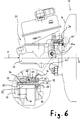
- each fastening part 68 has at its left end in FIG. 6 a head 78 with which he is on the end face facing him of the fastening part 68 can support one axially adjoining, groove-shaped section 80 smaller Diameter followed by an axial section 82 with something enlarged diameter to which there is a fastening section 84 connects, the outer diameter of which approximately corresponds to the groove-shaped section 80.
- the head 78 is then positioned by means of a holding device is held and it is on the in the brake booster housing 12 arranged end face of the Fastening part 68 at 69 by means of a knife-like tool performed a caulking process, which is part of the Material of the fastener 68 radially inward toward on the fastening section 84 of the connecting bolt 50 'deformed.
- the plastically deformed material penetrates into one Knurling 86 formed on the mounting portion 84 one, so that an airtight, twist and shift secured Connection between the fastening part 68 and the connecting bolt 50 'is made.
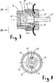
- FIGS. 7 and 8 show a comparison with the third exemplary embodiment somewhat modified fourth embodiment shown, in Figures 7 and 8 only those in relevant components of the brake booster / Master cylinder unit are shown.
- the fourth The embodiment between the here with 68 'designated sleeve-shaped fastening part and a again modified connecting pin labeled 50 '' no longer achieved by a caulking process, but by a shear pin 88 which the fastening part 68 'and radially penetrates the head 78 'of the connecting bolt 50' '.
- the Value of the previously defined pressure force, from which it is exceeded a displacement of the master cylinder in the brake booster housing should be possible through which Determines shear pin 88, the ends of which exceed one Shear off the previously defined axial force and thus a displacement of the master cylinder housing 32 relative to the or enable the connecting bolt 50 ''.
- the last three exemplary embodiments described furthermore the advantage of easier dismantling of the master cylinder, since the latter is separated from the brake booster without the brake booster from the body wall, to which it is attached, must be dismantled and without having to take out the connecting bolt or bolts.
Landscapes
- Engineering & Computer Science (AREA)
- Mechanical Engineering (AREA)
- Transportation (AREA)
- Physics & Mathematics (AREA)
- General Physics & Mathematics (AREA)
- Automation & Control Theory (AREA)
- Braking Systems And Boosters (AREA)
- Braking Arrangements (AREA)
Description
- Fig. 1
- den Längsschnitt durch ein erstes Ausführungsbeispiel einer erfindungsgemäßen Bremskraftverstärker/Hauptzylinder-Einheit im eingebauten Zustand,
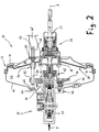
- Fig. 2
- die Ansicht aus Fig.1, nachdem eine Druckkraft längs einer Achse A von außen auf den Hauptzylinder eingewirkt hat,
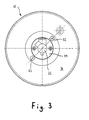
- Fig. 3
- die Ansicht III-III aus Fig.1,
- Fig. 4
- eine der Ansicht aus Fig.3 entsprechende Ansicht eines zweiten Ausführungsbeispiels einer erfindungsgemäßen Bremskraftverstärker/Hauptzylinder-Einheit,
- Fig. 5
- ein Detail des zweiten Ausführungsbeispieles in vergrößerter, räumlicher Darstellung,
- Fig.6
- ein drittes Ausführungsbeispiel einer erfindungsgemäßen Bremskraftverstärker/Hauptzylinder-Einheit, wobei die entscheidenden Details in vergrößerter undteilweise geschnittener Ansicht dargestellt sind,
- Fig.7
- schematisch die entscheidenden Details eines viertenAusführungsbeispiels einer erfindungsgemäßen Brems-kraftverstärker/Hauptzylinder-Einheit im Schnitt,
- Fig.8
- die Ansicht VIII-VIII aus Fig.7, und
- Fig.9
- eine der Fig.6 ähnliche Darstellung eines fünften Ausführungsbeispiels einer erfindungsgemäßen Bremskraftverstärker/Hauptzylinder-Einheit.
Claims (28)
- Bremskraftverstärker/Hauptzylinder-Einheit für eine Fahrzeugbremsanlage, mit einem Bremskraftverstärker (10), der ein insbesondere mindestens zweiteiliges Gehäuse (12) mit zwei einander gegenüberliegenden, äußeren Gehäusewänden (14, 16), denen Befestigungselemente für eine Karosseriewand bzw. für einen sich längs einer Achse (A) erstreckenden Hauptzylinder (30) zugeordnet sind, und zumindest eine bewegliche Wand (20) aufweist, die den Gehäuseinnenraum in zwei Kammern (22, 24) unterteilt und eine Kraft über ein Ausgangsglied auf den Hauptzylinder (30) überträgt, wenn in Abhängigkeit von einer an einem Eingangsglied (27) wirksamen Kraft zwischen den Kammern (22, 24) ein Druckunterschied herrscht, wobei die Befestigungselemente an den Enden mindestens eines Verbindungsbolzens (50, 50', 50'', 50''') angeordnet sind, der sich von einer äußeren Gehäusewand (14) durch die bewegliche Wand (20) hindurch zur gegenüberliegenden, äußeren Gehäusewand (16) erstreckt und gegen die bewegliche Wand (20) abgedichtet ist, und wobei der Hauptzylinder (30) ein Gehäuse (32) mit einer Halterung (34) hat, die von dem oder mehreren Verbindungsbolzen (50, 50', 50'', 50''') durchsetzt ist, dadurch gekennzeichnet, daß das Hauptzylindergehäuse (32) mit seiner Halterung (34) sich nach Überschreiten einer vorher festgelegten, in Richtung der Achse (A) auf es wirkenden Druckkraft relativ zu dem oder den Verbindungsbolzen (50, 50', 50'', 50''') in das Bremskraftverstärkergehäuse (12) hinein verschiebt.
- Bremskraftverstärker/Hauptzylinder-Einheit nach Anspruch 1, dadurch gekennzeichnet, daß die Einheit zur Befestigung an einer Karosseriewand eines Fahrzeugs vorgesehen ist, und daß die vorher festgelegte Druckkraft, nach deren Überschreiten sich das Hauptzylindergehäuse (32) relativ zu dem oder den Verbindungsbolzen (50, 50', 50", 50"') in das Bremskraftverstärkergehäuse (12) hinein verschiebt, kleiner ist als eine Kraft, die zur Verformung der genannten Karosseriewand nötig ist.
- Bremskraftverstärker/Hauptzylinder-Einheit nach Anspruch 1 oder 2, dadurch gekennzeichnet, daß die Halterung (34) durch einen mit dem Hauptzylindergehäuse (32) verbundenen, radialen Flansch (36) gebildet ist, der innerhalb des Bremskraftverstärkergehäuses (12) angeordnet ist.
- Bremskraftverstärker/Hauptzylinder-Einheit nach Anspruch 3, dadurch gekennzeichnet, daß der Flansch (36) innen an der dem Hauptzylinder (30) benachbarten äußeren Gehäusewand (14) des Bremskraftverstärkergehäuses (12) anliegt.
- Bremskraftverstärker/Hauptzylinder-Einheit nach einem der vorhergehenden Ansprüche, dadurch gekennzeichnet, daß eine äußere Gehäusewand (14) des Bremskraftverstärkergehäuses (12) einen insbesondere axial nach außen hervorragenden, stutzenförmigen Abschnitt (46) aufweist, der einen dem Bremskraftverstärkergehäuse (12) benachbarten Befestigungsflansch (44) des Hauptzylindergehäuses (32) umgibt.
- Bremskraftverstärker/Hauptzylinder-Einheit nach Anspruch 5, dadurch gekennzeichnet, daß der Befestigungsflansch (44) des Hauptzylindergehäuses (32) in Draufsicht im wesentlichen rautenförmig ist.
- Bremskraftverstärker/Hauptzylinder-Einheit nach Anspruch 5 oder 6, dadurch gekennzeichnet, daß der stutzenförmige Abschnitt (46) gegenüber dem Befestigungsflansch (44) des Hauptzylindergehäuses (32) abgedichtet ist.
- Bremskraftverstärker/Hauptzylinder-Einheit nach einem der vorhergehenden Ansprüche, dadurch gekennzeichnet, daß der Wert der zuvor festgelegten Druckkraft durch eine im Bremskraftverstärkergehäuse (12) angeordnete und die bewegliche Wand (20) in ihre Ausgangslage vorspannende Rückstellfeder (45) bestimmt wird, deren eines Ende sich am Hauptzylindergehäuse (32) oder dessen Halterung (34) abstützt.
- Bremskraftverstärker/Hauptzylinder-Einheit nach einem der vorhergehenden Ansprüche, dadurch gekennzeichnet, daß der oder die Verbindungsbolzen (50) in dem Längsabschnitt, mit dem sie die Halterung (34) durchsetzen, einen vergrößerten Durchmesser aufweisen.
- Bremskraftverstärker/Hauptzylinder-Einheit nach Anspruch 1 oder 2, dadurch gekennzeichnet, daß die Halterung (34) zumindest ein hülsenförmiges Befestigungsteil (68, 68') aufweist, welches die dem Hauptzylinder zugewandte, äußere Gehäusewand (14) des Bremskraftverstärkergehäuses (12) durchsetzt und mit einer radial nach außen vorspringenden Schulter (70) versehen ist, an der sich die Gehäusewand (14) abstützt.
- Bremskraftverstärker/Hauptzylinder-Einheit nach Anspruch 10, dadurch gekennzeichnet, daß die Gehäusewand (14) mit der Schulter (70) des Befestigungsteils (68, 68') verstemmt ist.
- Bremskraftverstärker/Hauptzylinder-Einheit nach Anspruch 10 oder 11, dadurch gekennzeichnet, daß jedes hülsenförmige Befestigungsteil (68, 68') von einem Verbindungsbolzen (50', 50'') durchsetzt ist.
- Bremskraftverstärker/Hauptzylinder-Einheit nach Anspruch 12, dadurch gekennzeichnet, daß das hülsenförmige Befestigungsteil (68, 68') einen Gewindeabschnitt (74) aufweist, der mit einem Außengewinde (75) versehen ist und durch einen Befestigungsflansch (44) des Hauptzylindergehäuses (32) hindurchragt.
- Bremskraftverstärker/Hauptzylinder-Einheit nach Anspruch 13, dadurch gekennzeichnet, daß ein Scherstift (88) das hülsenförmige Befestigungsteil (68') und den sich dadurch erstreckenden Verbindungsbolzen (50'') radial durchsetzt, so daß der Wert der vorher festgelegten Druckkraft durch den Scherstift (88) bestimmt wird.
- Bremskraftverstärker/Hauptzylinder-Einheit nach Anspruch 14, dadurch gekennzeichnet, daß eine Gewindehülse (96) den Befestigungsflansch (44) mit dem hülsenförmigen Befestigungsteil (68') verspannt, wobei die Gewindehülse (96) einen Flanschaufnahmeabschnitt und eine radial nach außen vorstehende, vorzugsweise umlaufende Anschlagschulter (98) aufweist.
- Bremskraftverstärker/Hauptzylinder-Einheit nach Anspruch 13, dadurch gekennzeichnet, daß der sich durch das hülsenförmige Befestigungsteil (68) erstreckende Verbindungsbolzen (50') einen mit einer Rändelung (86) versehenen Befestigungsabschnitt (84) aufweist, in den ein entsprechender Abschnitt des hülsenförmigen Befestigungsteils (68) verstemmt ist, so daß der Wert der vorher festgelegten Druckkraft durch die zuvor genannte Verstemmverbindung bestimmt wird.
- Bremskraftverstärker/Hauptzylinder-Einheit nach Anspruch 16, dadurch gekennzeichnet, daß eine Mutter (76) den Befestigungsflansch (44) mit dem hülsenförmigen Befestigungsteil (68) verspannt, wobei das hülsenförmige Befestigungsteil (68) einen sich axial an die Schulter (70) anschließenden Flanschaufnahmeabschnitt (72) aufweist, der einen größeren Durchmesser als der sich daran anschließende Gewindeabschnitt (74) hat.
- Bremskraftverstärker/Hauptzylinder-Einheit nach Anspruch 1 oder 2, dadurch gekennzeichnet, daß die Halterung (34) zumindest einen an der Innenseite der dem Hauptzylinder zugewandten äußeren Gehäusewand (14) des Bremskraftverstärkergehäuses (12) anliegenden Übertragungsring (100) aufweist, der auf einem Verbindungsbolzen (50''') angeordnet ist und sich auf seiner von der Gehäusewand (14) abgewandten Seite gegen einen Federring (102) abstützt, der in einer auf dem Verbindungsbolzen (50''') vorhandenen Ringnut (104) sitzt, so daß der Wert der vorher festgelegten Druckkraft durch die zum Drücken des Federrings (102) aus der Ringnut (104) erforderliche Axialkraft bestimmt wird.
- Bremskraftverstärker/Hauptzylinder-Einheit nach Anspruch 18, dadurch gekennzeichnet, daß eine Schraubmutter (108) den Befestigungsflansch (44) mit dem Übertragungsring (100) verspannt, wobei die Schraubmutter (108) einen Flanschaufnahmeabschnitt (110) aufweist.
- Bremskraftverstärker/Hauptzylinder-Einheit nach einem der vorhergehenden Ansprüche, dadurch gekennzeichnet, daß der oder jeder Verbindungsbolzen (50, 50', 50'', 50''') hohl ist.
- Bremskraftverstärker/Hauptzylinder-Einheit nach einem der vorhergehenden Ansprüche, dadurch gekennzeichnet, daß der bzw. jeder Verbindungsbolzen (50, 50', 50'', 50''') bezüglich der zur beweglichen Wand (20) normalen Mittelachse des Gehäuses (12) seitlich versetzt angeordnet ist.
- Bremskraftverstärker/Hauptzylinder-Einheit nach Anspruch 21, dadurch gekennzeichnet, daß mehrere Verbindungsbolzen (50, 50', 50'', 50''') in gleichen Abständen voneinander um die Mittelachse des Gehäuses (12) verteilt angeordnet sind.
- Bremskraftverstärker/Hauptzylinder-Einheit nach Anspruch 22, dadurch gekennzeichnet, daß insgesamt zwei Verbindungsbolzen (50, 50', 50'', 50''') vorhanden und bezüglich der Mittelachse des Gehäuses (12) einander diametral gegenüber angeordnet sind.
- Bremskraftverstärker/Hauptzylinder-Einheit nach einem der vorhergehenden Ansprüche, dadurch gekennzeichnet, daß mindestens ein Ende (56) des bzw. jedes Verbindungsbolzens (50, 50', 50'', 50''') durch die entsprechende äußere Gehäusewand (16) nach außen ragt.
- Bremskraftverstärker/Hauptzylinder-Einheit nach Anspruch 24, dadurch gekennzeichnet, daß die nach außen ragenden Enden (56) mit je einem Gewinde (58) versehen sind.
- Bremskraftverstärker/Hauptzylinder-Einheit nach einem der vorhergehenden Ansprüche, dadurch gekennzeichnet, daß der bzw. jeder Verbindungsbolzen (50, 50', 50'', 50''') auf zumindest einem seiner Endbereiche eine radial nach außen vorspringende, vorzugsweise umlaufende Schulter (62, 64) aufweist, die eine Einwärtsbewegung der zugeordneten äußeren Gehäusewand (14, 16) begrenzt.
- Bremskraftverstärker/Hauptzylinder-Einheit nach einem der vorhergehenden Ansprüche, dadurch gekennzeichnet, daß in dem Kraftübertragungsweg von dem Ausgangsglied des Bremskraftverstärkers (10) zum Hauptzylinder (30) eine Sollbruchstelle vorhanden ist, die bei einer längs der Achse (A) wirkenden Druckkraft bricht, bevor sich die Karosseriewand des Fahrzeugs verformt.
- Bremskraftverstärker/Hauptzylinder-Einheit nach einem der Ansprüche 1 bis 26, dadurch gekennzeichnet, daß der Hydraulikkreis des Hauptzylinders (30) eine Überlastsicherung enthält, die eine durch die Verschiebung des Hauptzylindergehäuses (32) in das Bremskraftverstärkergehäuse (12) mögliche, übermäßige Hydraulikdruckerhöhung abbaut bzw. begrenzt.
Applications Claiming Priority (2)
| Application Number | Priority Date | Filing Date | Title |
|---|---|---|---|
| DE29514063U | 1995-09-01 | ||
| DE29514063U DE29514063U1 (de) | 1995-09-01 | 1995-09-01 | Bremskraftverstärker/Hauptzylinder-Einheit mit Verbindungsbolzen |
Publications (2)
| Publication Number | Publication Date |
|---|---|
| EP0760319A1 EP0760319A1 (de) | 1997-03-05 |
| EP0760319B1 true EP0760319B1 (de) | 2000-05-31 |
Family
ID=8012504
Family Applications (1)
| Application Number | Title | Priority Date | Filing Date |
|---|---|---|---|
| EP96113957A Expired - Lifetime EP0760319B1 (de) | 1995-09-01 | 1996-08-30 | Bremskraftverstärker/Hauptzylinder-Einheit mit Verbindungsbolzen |
Country Status (3)
| Country | Link |
|---|---|
| EP (1) | EP0760319B1 (de) |
| DE (2) | DE29514063U1 (de) |
| ES (1) | ES2148646T3 (de) |
Families Citing this family (4)
| Publication number | Priority date | Publication date | Assignee | Title |
|---|---|---|---|---|
| DE19748492A1 (de) * | 1997-11-03 | 1999-07-15 | Itt Mfg Enterprises Inc | Gehäuseteil für einen pneumatischen Bremskraftverstärker |
| US6772674B2 (en) * | 2002-11-12 | 2004-08-10 | Delphi Technologies, Inc. | Tie rod apparatus and method for assembling a vacuum booster |
| FR2882315B1 (fr) * | 2005-02-18 | 2007-05-18 | Bosch Gmbh Robert | Dispositif de freinage d'un vehicule, maitre-cylindre compris dans un tel dispositif de freinage et piston primaire pour un tel maitre-cylindre |
| DE102005033423B4 (de) * | 2005-07-18 | 2007-04-19 | Lucas Automotive Gmbh | Gelenkverbindung, insbesondere zwischen einem Krafteingangsglied eines Bremskraftverstärkers und einem Anschlussteil, Bremskraftverstärker und Verfahren zur Herstellung einer derartigen Gelenkverbindung |
Family Cites Families (1)
| Publication number | Priority date | Publication date | Assignee | Title |
|---|---|---|---|---|
| PH18419A (en) * | 1977-10-20 | 1985-06-26 | Girling Ltd | Servo bosster for vehicle breaking system |
-
1995
- 1995-09-01 DE DE29514063U patent/DE29514063U1/de not_active Expired - Lifetime
-
1996
- 1996-08-30 DE DE59605348T patent/DE59605348D1/de not_active Expired - Fee Related
- 1996-08-30 EP EP96113957A patent/EP0760319B1/de not_active Expired - Lifetime
- 1996-08-30 ES ES96113957T patent/ES2148646T3/es not_active Expired - Lifetime
Also Published As
| Publication number | Publication date |
|---|---|
| EP0760319A1 (de) | 1997-03-05 |
| DE29514063U1 (de) | 1997-01-09 |
| ES2148646T3 (es) | 2000-10-16 |
| DE59605348D1 (de) | 2000-07-06 |
Similar Documents
| Publication | Publication Date | Title |
|---|---|---|
| DE3532769C2 (de) | ||
| DE602004002232T2 (de) | Elektronisches Gerät | |
| DE69422311T2 (de) | Fluidumgetriebene federspeicherbremsenbetätigungsvorrichtung mit verbesserter druckplatte | |
| DE2845794C2 (de) | Bremskraftverstärker | |
| EP4017781B1 (de) | Lenksäule für ein kraftfahrzeug | |
| DE102021125699A1 (de) | Energieabsorbierende bügelbaugruppe mit metallabbrechmerkmal | |
| EP0850807B1 (de) | Stossverzehrvorrichtung für ein Kraftfahrzeug | |
| DE29707352U1 (de) | Straffer für einen Sicherheitsgurt | |
| EP3242827A1 (de) | Lenksäule mit flexibel montierbarem lagersitz | |
| EP4185760B1 (de) | Antriebsanordnung für eine klappe eines kraftfahrzeugs | |
| DE69506708T2 (de) | Baueinheit aus unterdruck-bremskraftverstärker und hauptbremszylinder | |
| EP0901950B1 (de) | Unterdruckbremskraftverstärker zur Einstellung eines Bremsdrucks in einer Hilfskraftbremsanlage | |
| DE69523632T2 (de) | Pneumatische bremskraftverstärker-hauptzylindereinheit | |
| EP0760319A1 (de) | Bremskraftverstärker/Hauptzylinder-Einheit mit Verbindungsbolzen | |
| DE102011116590A1 (de) | Kolben-Zylinder-Einheit, Verfahren zum Betrieb und Verfahren zur Herstellung einer solchen Kolben-Zylinder-Einheit sowie fahrzeugintegriertes Personensicherheitssystem | |
| DE4208384A1 (de) | Unterdruck-bremskraftverstaerker | |
| EP0810931B1 (de) | Kraftfahrzeug-betätigungseinheit | |
| DE19634257A1 (de) | Bremsanlage für ein Fahrzeug | |
| EP1637426B1 (de) | Puffersystem | |
| DE19524492B4 (de) | Bremskraftverstärker mit Verbindungsbolzen | |
| DE69907173T2 (de) | Vorrichtung zur vesprödung einer kraftfahrzeugpedal-drehachse | |
| DE69709116T2 (de) | Bremskraftverstärker mit hydraulischer reaktion und mit grösserer sicherheit | |
| DE2849045A1 (de) | Tandemhauptzylinder | |
| DE3029911A1 (de) | Bremskraftverstaerker fuer kraftfahrzeuge | |
| DE19524503A1 (de) | Bremskraftverstärker/Hauptzylinder-Einheit mit Verbindungsbolzen |
Legal Events
| Date | Code | Title | Description |
|---|---|---|---|
| PUAI | Public reference made under article 153(3) epc to a published international application that has entered the european phase |
Free format text: ORIGINAL CODE: 0009012 |
|
| AK | Designated contracting states |
Kind code of ref document: A1 Designated state(s): DE ES FR GB IT |
|
| 17P | Request for examination filed |
Effective date: 19970326 |
|
| 17Q | First examination report despatched |
Effective date: 19981228 |
|
| GRAG | Despatch of communication of intention to grant |
Free format text: ORIGINAL CODE: EPIDOS AGRA |
|
| GRAG | Despatch of communication of intention to grant |
Free format text: ORIGINAL CODE: EPIDOS AGRA |
|
| GRAH | Despatch of communication of intention to grant a patent |
Free format text: ORIGINAL CODE: EPIDOS IGRA |
|
| RAP1 | Party data changed (applicant data changed or rights of an application transferred) |
Owner name: LUCAS INDUSTRIES LIMITED |
|
| GRAH | Despatch of communication of intention to grant a patent |
Free format text: ORIGINAL CODE: EPIDOS IGRA |
|
| GRAA | (expected) grant |
Free format text: ORIGINAL CODE: 0009210 |
|
| AK | Designated contracting states |
Kind code of ref document: B1 Designated state(s): DE ES FR GB IT |
|
| GBT | Gb: translation of ep patent filed (gb section 77(6)(a)/1977) |
Effective date: 20000612 |
|
| REF | Corresponds to: |
Ref document number: 59605348 Country of ref document: DE Date of ref document: 20000706 |
|
| PGFP | Annual fee paid to national office [announced via postgrant information from national office to epo] |
Ref country code: GB Payment date: 20000727 Year of fee payment: 5 |
|
| ET | Fr: translation filed | ||
| PGFP | Annual fee paid to national office [announced via postgrant information from national office to epo] |
Ref country code: DE Payment date: 20000825 Year of fee payment: 5 |
|
| PGFP | Annual fee paid to national office [announced via postgrant information from national office to epo] |
Ref country code: FR Payment date: 20000828 Year of fee payment: 5 |
|
| ITF | It: translation for a ep patent filed | ||
| REG | Reference to a national code |
Ref country code: ES Ref legal event code: FG2A Ref document number: 2148646 Country of ref document: ES Kind code of ref document: T3 |
|
| PLBE | No opposition filed within time limit |
Free format text: ORIGINAL CODE: 0009261 |
|
| STAA | Information on the status of an ep patent application or granted ep patent |
Free format text: STATUS: NO OPPOSITION FILED WITHIN TIME LIMIT |
|
| 26N | No opposition filed | ||
| PGFP | Annual fee paid to national office [announced via postgrant information from national office to epo] |
Ref country code: ES Payment date: 20010814 Year of fee payment: 6 |
|
| PG25 | Lapsed in a contracting state [announced via postgrant information from national office to epo] |
Ref country code: GB Free format text: LAPSE BECAUSE OF NON-PAYMENT OF DUE FEES Effective date: 20010830 |
|
| PG25 | Lapsed in a contracting state [announced via postgrant information from national office to epo] |
Ref country code: FR Free format text: LAPSE BECAUSE OF NON-PAYMENT OF DUE FEES Effective date: 20020430 |
|
| PG25 | Lapsed in a contracting state [announced via postgrant information from national office to epo] |
Ref country code: DE Free format text: LAPSE BECAUSE OF NON-PAYMENT OF DUE FEES Effective date: 20020501 |
|
| REG | Reference to a national code |
Ref country code: FR Ref legal event code: ST |
|
| PG25 | Lapsed in a contracting state [announced via postgrant information from national office to epo] |
Ref country code: ES Free format text: LAPSE BECAUSE OF NON-PAYMENT OF DUE FEES Effective date: 20020831 |
|
| REG | Reference to a national code |
Ref country code: ES Ref legal event code: FD2A Effective date: 20030912 |
|
| PG25 | Lapsed in a contracting state [announced via postgrant information from national office to epo] |
Ref country code: IT Free format text: LAPSE BECAUSE OF NON-PAYMENT OF DUE FEES;WARNING: LAPSES OF ITALIAN PATENTS WITH EFFECTIVE DATE BEFORE 2007 MAY HAVE OCCURRED AT ANY TIME BEFORE 2007. THE CORRECT EFFECTIVE DATE MAY BE DIFFERENT FROM THE ONE RECORDED. Effective date: 20050830 |