EP0758575A1 - Clamping device set - Google Patents
Clamping device set Download PDFInfo
- Publication number
- EP0758575A1 EP0758575A1 EP96112769A EP96112769A EP0758575A1 EP 0758575 A1 EP0758575 A1 EP 0758575A1 EP 96112769 A EP96112769 A EP 96112769A EP 96112769 A EP96112769 A EP 96112769A EP 0758575 A1 EP0758575 A1 EP 0758575A1
- Authority
- EP
- European Patent Office
- Prior art keywords
- clamping
- adjusting rod
- clamping device
- tensioning
- fastening elements
- Prior art date
- Legal status (The legal status is an assumption and is not a legal conclusion. Google has not performed a legal analysis and makes no representation as to the accuracy of the status listed.)
- Withdrawn
Links
Images

Classifications
-
- B—PERFORMING OPERATIONS; TRANSPORTING
- B25—HAND TOOLS; PORTABLE POWER-DRIVEN TOOLS; MANIPULATORS
- B25B—TOOLS OR BENCH DEVICES NOT OTHERWISE PROVIDED FOR, FOR FASTENING, CONNECTING, DISENGAGING OR HOLDING
- B25B5/00—Clamps
- B25B5/06—Arrangements for positively actuating jaws
- B25B5/12—Arrangements for positively actuating jaws using toggle links
- B25B5/122—Arrangements for positively actuating jaws using toggle links with fluid drive
-
- B—PERFORMING OPERATIONS; TRANSPORTING
- B25—HAND TOOLS; PORTABLE POWER-DRIVEN TOOLS; MANIPULATORS
- B25B—TOOLS OR BENCH DEVICES NOT OTHERWISE PROVIDED FOR, FOR FASTENING, CONNECTING, DISENGAGING OR HOLDING
- B25B5/00—Clamps
- B25B5/16—Details, e.g. jaws, jaw attachments
Definitions
- the invention relates to an interchangeable tool kit for clamping workpieces, in particular for clamping body panels to be welded together using clamping devices according to the preamble of patent claim 1.
- Clamping devices of which one type is actuated, for example, with a pneumatic actuating cylinder and the other can be opened and closed by hand with an actuating lever, are sufficiently well known in detail per se (see, for example, DE-A-22 22 686 and DE -U-9 101 555.3).
- clamping devices are also used in particular in the manufacture of car bodies in order to fix body parts to be connected precisely in relation to one another and to subsequently connect them to one another in a suitable manner (see US-A-2 779 092).
- clamping devices When redesigning car bodies, manually operated and in this respect less expensive clamping devices are used to determine and determine all the necessary conditions in the production area for such newly designed car bodies.
- the invention is therefore based on the object to provide a tool change kit using clamping devices, which can be easily replaced in the sense that the manually operated clamps initially used for the redesign of a body can be replaced by automatically operated clamping devices on series production devices , without having to make any changes to the devices for series production, whereby, as far as the hand-operated clamps used first are concerned, they are also largely functionally adapted to the automatically actuated clamping devices, so that the same arrangement and functional relationships for later use automatically actuatable clamping devices are available.
- the two clamping devices forming the tool change kit ultimately differ only in that the drive for the automatically actuated clamping device consists, for example, of a pneumatic actuating cylinder and the other, second clamping device does have a manual actuation lever which Adjustment movement of the hand lever is implemented in approximately the same way as in the automatically actuated clamping device on the clamping arm.
- this also creates the possibility of identically designing the fastening elements for the counterbearing to the tensioning arm on the head pieces of both tensioning devices, since the design of the head pieces of both tensioning devices largely correspond.
- fastening elements there are various embodiments for the fastening elements, but in this regard, an embodiment is preferred in which the fastening elements are formed from two transverse bolt receiving bores in the flank walls of the head pieces which delimit an insertion gap.
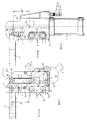
- the tool change kit consists of the first, automatically actuated clamping device I (FIG. 2) and the manually operated clamping device according to FIG. 1.
- first clamping device I which is provided with an actuator 1 in the form of a pneumatic actuating cylinder
- Has a clamping arm 2 which can be pivoted with the axially adjustable adjusting rod 3 (is piston rod of the pneumatic cylinder) with the intermediate member 4 from the actuator 1, that is, into the closed and open position.
- an intermediate member 4 is connected in an articulated manner to a lever 4 ', which lever 4' is fixedly connected to the pivot shaft of the tensioning arm 2 which is mounted in the pivot bearing 7.
- the second tensioning device II according to the illustrated embodiment also applies in a known manner that its tensioning arm 2 'can be actuated via an intermediate member 4' 'by a hand lever 1'.
- the tool change kit it is formed from the first clamping device I and the second clamping device II, of which the first clamping device I with an axially movable adjusting rod 2 having an automatic actuator 1 (pneumatic cylinder) and the second clamping device II a hand lever 1 'can be actuated, with two clamping devices I, II with respect to the pivot bearings 7 their essentially identical clamping arms 2, 2 ', the fastening elements 5 are designed in accordance with distance, arrangement, shape and dimensions, and that an adjusting rod 3' is provided on the second clamping device II for the coupling between clamping arm 2 'and hand lever 1' whose displacement SW corresponds to the displacement SW 'of the axially movable adjusting rod 3 of the first clamping device I.
- the clamping arm 2 'with respect to the head piece 6' is arranged centrally between the flank walls 13 of the head piece 6 ', but it would also be possible without further ado to have the clamping arm 2' also on the outside of the head piece 6 'as in the first tensioning device I shown in FIG. 2 and vice versa.
- An outside arrangement of the clamping arms 2, 2 ' is preferred, however, since these are then easier to replace.
- the second clamping device II need not be largely identical to the first clamping device I, since in the preliminary stage of series production, foreign particles do not count to the extent in the head piece 2, and the second, manually operable clamping device II as shown in FIG. 1 must be formed for the tool change kit.
- the lower end of the actuating rod 3 ' is articulated to a foot piece 8 of the hand lever 1' in the second clamping device II, which in turn is pivotably mounted on the head piece 6 'and that Pivot bearing 9 is arranged on the extended longitudinal center line 10 in the adjusting rod 3 'which is in the closed position.
- the opening position of the tensioning device II or of its tensioning arm 2 ' is indicated by dashed lines in FIG. 1.
- the fastening elements 5 of the two clamping devices I, II are formed, as shown in the exemplary embodiments in FIGS. 1, 2, from two transverse bolt receiving bores 11 in the side walls 13 of the head pieces 6, 6 'which delimit an insertion gap 12.
- the counter-support element for the support of sheets to be clamped to one another is designated by G in FIG. 3, the end of this counter-support G which can be inserted into the gap 12 not being shown, which of course has corresponding through-bores for the transverse bolts Q, which in the exemplary embodiment according to FIG. 3 are mounted in a precisely fitting manner in bushings B inserted into the side walls 13, which, as shown, ensure that the side walls 13 are not bent against one another when the nuts are tightened, thereby hindering the mobility of the actuating mechanism.
- the arrangement of the fastening elements 5 in FIGS. 1, 2, which is only shown on the tension arm side, is not mandatory, that is, these can also be provided only on the rear side or additionally on the rear side of the head pieces 6, 6 ', which does not depend on the particular installation conditions on the production facilities concerned (not shown) depends on the welding of body panels.
Abstract
Description
Die Erfindung betrifft einen Werkzeug-Wechselbausatz für das Festspannen von Werkstücken, insbesondere für das Zusammenspannen von zu verschweißenden Karosserieblechen unter Verwendung von Spannvorrichtungen gemäß Oberbegriff des Patentanspruches 1.The invention relates to an interchangeable tool kit for clamping workpieces, in particular for clamping body panels to be welded together using clamping devices according to the preamble of
Spannvorrichtungen, von denen die eine Art bspw. mit einem pneumatischen Stellzylinder betätigt wird und die andere mit einem Betätigungshebel von Hand geöffnet und geschlossen werden kann, sind für sich im einzelnen betrachtet hinlänglich bekannt (siehe bspw. DE-A-22 22 686 und DE-U-9 101 555.3). Abgesehen davon, daß derartige Spannvorrichtungen für die unterschiedlichsten Festspannaufgaben verwendet werden, kommen diese insbesondere auch bei der Fertigung von Autokarosserien zum Einsatz, um zu verbindende Karosserieteile lagegenau zueinander festzulegen und um diese anschließend miteinander in geeigneter Weise verbinden zu können (siehe US-A-2 779 092). Bei der Neukonzeption von Karosserien werden dabei zunächst von Hand betätigbare und insoweit kostengünstigere Spannvorrichtungen verwendet, um alle erforderlichen Gegebenheiten im Fertigungsbereich für derartig neu konzipierte Karosserien zu ermitteln und festzulegen. Wenn dann eine solche Karosserie in die Serienfertigung gehen soll, können die per Hand betätigbaren Spannvorrichtungen nicht mehr verwendet werden, da für eine Serienfertigung diese einer weitestgehend automatisierten Fertigung nicht genügen können, d.h., für die für eine Serienfertigung vorgesehenen Fertigungseinrichtungen ist es also notwendig, diese mit automatisch arbeitenden Spannvorrichtungen auszurüsten. Dieser Austausch bzw. Wechsel von handbetätigbaren Spannvorrichtungen auf automatisch arbeitende Spannvorrichtungen ist jedoch insoweit problematisch, als sich heute verfügbare handbetätigte und automatisch arbeitende Spannvorrichtungen in ihrer Konstruktion beträchtlich unterscheiden, und zwar was sowohl die Stellmechanik als auch die Befestigungselemente betrifft, an denen die Gegenauflagestücke für die gegeneinander zu verspannenden Karosserieteile aufzulegen sind, um diese in Schließstellung des Spannarmes mit diesem festzulegen. Um die vorher mit Hand betätigbaren Spannvorrichtungen ermittelten Gegebenheiten an Fertigungseinrichtungen für die Serienfertigung zu reproduzieren, soweit dies mit den bisher verfügbaren Spannvorrichtungen beider Arten praktiziert wird, verlangt dies an den Fertigungseinrichtungen für die tatsächliche Serienfertigung entsprechende und nicht unbeträchtliche Anpassungsmaßnahmen, um an diesen nunmehr in etwa funktionsentsprechende, automatisch betätigbare Spannvorrichtungen installieren zu können. Ein idealer und weitgehend funktionsidentischer Wechsel ist dabei mit den heute verfügbaren Spannvorrichtungen praktisch nicht möglich, da sich, wie gesagt, sogenannte Handspanner von automatisch arbeitenden Spannvorrichtungen nicht nur bezgl. ihrer Verstellmechaniken nicht unwesentlich unterscheiden, sondern insbesondere auch hinsichtlich der Ausbildung und Anordnung ihrer Befestigungselemente.Clamping devices, of which one type is actuated, for example, with a pneumatic actuating cylinder and the other can be opened and closed by hand with an actuating lever, are sufficiently well known in detail per se (see, for example, DE-A-22 22 686 and DE -U-9 101 555.3). In addition to the fact that such clamping devices are used for a wide variety of clamping tasks, they are also used in particular in the manufacture of car bodies in order to fix body parts to be connected precisely in relation to one another and to subsequently connect them to one another in a suitable manner (see US-A-2 779 092). When redesigning car bodies, manually operated and in this respect less expensive clamping devices are used to determine and determine all the necessary conditions in the production area for such newly designed car bodies. If such a body is then to go into series production, the manually operated clamping devices can no longer be used, since for series production these cannot satisfy largely automated production, that is, for the production facilities provided for series production, it is necessary to do so to be equipped with automatically operating clamping devices. This exchange or change from manually operated clamping devices to automatically operating clamping devices is problematic insofar as hand-operated and automatically working clamping devices available today differ considerably in their construction, both in terms of the adjusting mechanism and the fastening elements on which the counter-support pieces for the Body parts to be clamped against each other are to be placed in order to fix them in the closed position of the clamping arm. To the clamping devices that can be operated manually beforehand To reproduce determined conditions on production facilities for series production, insofar as this is practiced with the clamping devices of both types available so far, this requires corresponding and not inconsiderable adaptation measures on the production facilities for the actual series production in order to install approximately functionally appropriate, automatically actuable clamping devices on them can. An ideal and largely functionally identical change is practically not possible with the clamping devices available today, since, as I said, so-called manual clamps differ from automatically operating clamping devices not only not insignificantly with regard to their adjustment mechanisms, but also in particular with regard to the design and arrangement of their fastening elements.
Der Erfindung liegt somit die Aufgabe zugrunde, einen Werkzeug-Wechselbausatz unter Verwendung von Spannvorrichtungen zu schaffen, die ohne weiteres in dem Sinne dahingehend ausgetauscht werden können, daß die zunächst für die Neukonzeption einer Karosserie verwendeten handbetätigbaren Spanner an Serienfertigungseinrichtungen durch automatisch betätigbare Spannvorrichtungen ersetzt werden können, ohne dabei an den Einrichtungen für die Serienfertigung Änderungen vornehmen zu müssen, wobei, was die zuerst benutzten handbetätigbaren Spanner betrifft, diese auch weitestgehend an die automatisch betätigbaren Spannvorrichtungen funktionell angepaßt sind, um von vornherein die gleichen Anordnungs- und Funktionsverhältnisse für den späteren Einsatz automatisch betätigbarer Spannvorrichtungen vorliegen zu haben.The invention is therefore based on the object to provide a tool change kit using clamping devices, which can be easily replaced in the sense that the manually operated clamps initially used for the redesign of a body can be replaced by automatically operated clamping devices on series production devices , without having to make any changes to the devices for series production, whereby, as far as the hand-operated clamps used first are concerned, they are also largely functionally adapted to the automatically actuated clamping devices, so that the same arrangement and functional relationships for later use automatically actuatable clamping devices are available.
Diese Aufgabe ist mit einem Werkzeug-Wechselbausatz unter Verwendung von Spannvorrichtungen nach der Erfindung durch die im Kennzeichen des Patentanspruches 1 angeführten Merkmale gelöst.This object is achieved with a tool changer kit using clamping devices according to the invention by the features stated in the characterizing part of
Die beiden den Werkzeug-Wechselbausatz bildenden Spannvorrichtungen unterscheiden sich letztlich nur dadurch, daß der Antrieb für die automatisch betätigbare Spannvorrichtung aus bspw. einem pneumatischen Stellzylinder besteht und die andere, zweite Spannvorrichtung zwar einen Handbetätigungshebel aufweist, die Verstellbewegung des Handhebels aber in angenähert gleicher Weise wie bei der automatisch betätigbaren Spannvorrichtung auf den Spannarm umgesetzt wird. Damit ist aber gleichzeitig auch die Möglichkeit geschaffen, an den Kopfstücken beider Spannvorrichtungen die Befestigungselemente für das Gegenlager zum Spannarm identisch auszubilden, da sich die Kopfstücke beider Spannvorrichtungen in ihrer Konstruktion weitestgehend entsprechen.The two clamping devices forming the tool change kit ultimately differ only in that the drive for the automatically actuated clamping device consists, for example, of a pneumatic actuating cylinder and the other, second clamping device does have a manual actuation lever which Adjustment movement of the hand lever is implemented in approximately the same way as in the automatically actuated clamping device on the clamping arm. At the same time, however, this also creates the possibility of identically designing the fastening elements for the counterbearing to the tensioning arm on the head pieces of both tensioning devices, since the design of the head pieces of both tensioning devices largely correspond.
Für die Kopplung des Handbetätigungshebels mit dem Spannarm an der zweiten Spannvorrichtung über die Stellstange gibt es zwar verschiedene Möglichkeiten, bevorzugt wird aber eine weitere Ausgestaltung dahingehend, daß das untere Ende der Stellstange der zweiten Spannvorrichtung an einem Fußstück des Handhebels angelenkt ist, das seinerseits schwenkbar am Kopfstück gelagert und das Schwenklager auf der verlängerten Längsmittellinie der sich in Schließstellung befindlichen Stellstange angeordnet ist.There are various options for coupling the manual control lever to the clamping arm on the second clamping device via the adjusting rod, but a further embodiment is preferred in that the lower end of the adjusting rod of the second clamping device is articulated on a foot piece of the manual lever, which in turn is pivotable on Headpiece mounted and the pivot bearing is arranged on the extended longitudinal center line of the actuating rod in the closed position.
Ebenso ergeben sich für die Befestigungselemente verschiedene Ausführungsformen, diesbezüglich wird aber eine Ausbildung dahingehend bevorzugt, bei der die Befestigungselemente aus zwei Querbolzenaufnahmebohrungen in den einen Einsatzspalt begrenzenden Flankenwänden der Kopfstücke gebildet sind.Likewise, there are various embodiments for the fastening elements, but in this regard, an embodiment is preferred in which the fastening elements are formed from two transverse bolt receiving bores in the flank walls of the head pieces which delimit an insertion gap.
Andere konstruktive Gestaltungen, soweit sie nicht die Verstellmechaniken und die Befestigungselemente betreffen und soweit sie an herkömmlichen Spannvorrichtungen bekannt sind, können dabei ohne weiteres auch an den beiden, den Wechselbausatz bildenden Spannvorrichtungen vorgesehen werden. So ist es bspw. ohne weiteres möglich, die Kopfstücke, um Schmutz- oder Fremdkörpereintritt in die Kopfstücke zu verhindern, geschlossen auszubilden und die Spannarme seitlich außen an den Kopfstücken anzuordnen, was - soweit bekannt - an handbetätigbaren Spannvorrichtungen bislang überhaupt noch nicht verwirklicht worden ist.Other structural designs, insofar as they do not relate to the adjustment mechanisms and the fastening elements and insofar as they are known on conventional tensioning devices, can also be readily provided on the two tensioning devices forming the interchangeable kit. For example, it is easily possible to form the head pieces closed in order to prevent dirt or foreign matter from entering the head pieces and to arrange the clamping arms laterally on the outside of the head pieces, which - as far as is known - has not yet been achieved with manually operated clamping devices .
Der erfindungsgemäße Werkzeug-Wechselbausatz wird nachfolgend anhand der zeichnerischen Darstellung von Ausführungsbeispielen näher erläutert.The tool change kit according to the invention is explained in more detail below with reference to the drawing of exemplary embodiments.
Es zeigt schematisch
- Fig. 1
- die zweite, zum Werkzeug-Wechselbausatz gehörende und handbetätigbare Spannvorrichtung;
- Fig. 2
- die erste, ebenfalls zum Werkzeug-Wechselbausatz gehörende automatisch betätigbare Spannvorrichtung;
- Fig. 3
- in Pfeilrichtung X gemäß Fig. 1, 2 gesehen, vergrößert und teilweise in Schnitt und Ansicht die identischen Befestigungselemente beider Spannvorrichtungen und
- Fig. 4
- einen Schnitt durch die zweite Spannvorrichtung gemäß Fig. 1 längs Linie IV-IV.
- Fig. 1
- the second, manually operated clamping device belonging to the tool change kit;
- Fig. 2
- the first automatically operable clamping device, also part of the tool change kit;
- Fig. 3
- 1, 2 seen in the direction of arrow X, enlarged and partly in section and view, the identical fastening elements of both clamping devices and
- Fig. 4
- a section through the second clamping device of FIG. 1 along line IV-IV.
Der Werkzeug-Wechselbausatz besteht aus der ersten, automatisch betätigbaren Spannvorrichtung I (Fig. 2) und aus der handbetätigbaren Spannvorrichtung gemäß Fig. 1. Bezüglich der ersten Spannvorrichtung I, die mit einem Stellantrieb 1 in Form eines Pneumatikstellzylinders versehen ist, weist diese in bekannter Weise einen Spannarm 2 auf, der mit der axial verstellbaren Stellstange 3 (ist Kolbenstange des Pneumatikzylinders) mit Zwischenglied 4 vom Stellantrieb 1 aus schwenkbar, d.h., in Schließ- und Öffnungsstellung bringbar ist. Bei diesem Ausführungsbeispiel ist ein Zwischenglied 4 gelenkig mit einem Hebel 4' verbunden, welcher Hebel 4' fest mit der im Schwenklager 7 gelagerten Schwenkwelle des Spannarmes 2 verbunden ist. Zunächst ohne Bezug auf Fig. 1 gilt für die zweite Spannvorrichtung II gemäß dargestelltem Ausführungsbeispiel ebenfalls in bekannter Weise, daß deren Spannarm 2' über ein Zwischenglied 4'' durch einen Handhebel 1' betätigbar ist.The tool change kit consists of the first, automatically actuated clamping device I (FIG. 2) and the manually operated clamping device according to FIG. 1. Regarding the first clamping device I, which is provided with an
Für den Werkzeug-Wechselbausatz ist nun wesentlich, daß dieser aus der ersten Spannvorrichtung I und der zweiten Spannvorrichtung II gebildet ist, von denen die erste Spannvorrichtung I mit einem eine axial bewegliche Stellstange 2 aufweisenden automatischen Stellantrieb 1 (Pneumatikzylinder) und die zweite Spannvorrichtung II mit einem Handhebel 1' betätigbar ist, wobei an beiden Spannvorrichtungen I, II in bezug auf die Schwenklager 7 ihrer im wesentlichen identisch ausgebildeten Spannarme 2, 2' die Befestigungselemente 5 distanz-, anordnungs-, form- und dimensionsentsprechend ausgebildet sind, und daß an der zweiten Spannvorrichtung II für die Kopplung zwischen Spannarm 2' und Handhebel 1' eine Stellstange 3' vorgesehen ist, deren Verstellweg SW dem Verstellweg SW' der axial beweglichen Stellstange 3 der ersten Spannvorrichtung I entspricht.It is now essential for the tool change kit that it is formed from the first clamping device I and the second clamping device II, of which the first clamping device I with an axially
Bei der zweiten, handbetätigbaren Spannvorrichtung II gemäß Fig. 1 ist der Spannarm 2' bezgl. des Kopfstückes 6' zwar mittig zwischen den Flankenwänden 13 des Kopfstückes 6' angeordnet, es wäre aber auch ohne weiteres möglich, den Spannarm 2' ebenfalls außen am Kopfstück 6' wie bei der ersten Spannvorrichtung I gemäß Fig. 2 anzuordnen und umgekehrt. Eine außenseitige Anordnung der Spannarme 2, 2' wird jedoch bevorzugt, da diese dann einfacher austauschbar sind. Insoweit und was die Zuordnung des Spannarmes 2' zum Kopfstück 6' betrifft, muß aber die zweite Spannvorrichtung II nicht weitgehend identisch wie die erste Spannvorrichtung I ausgebildet sein, da im Vorstadium zu einer Serienfertigung nicht in dem Maße mit einem Fremdpartikeleintritt in das Kopfstück gerechnet werden muß, d.h., zum Werkzeug-Wechselbausatz kann die erste, automatisch betätigbare Spannvorrichtung gemäß Fig. 2 ausgebildet sein und die zweite, handbetätigbare Spannvorrichtung II wie in Fig. 1 dargestellt.In the second, manually operable clamping device II according to FIG. 1, the clamping arm 2 'with respect to the head piece 6' is arranged centrally between the
Abgesehen von der beim Ausführungsbeispiel gemäß Fig. 2 verdeutlichten seitlichen Zuordnung des Spannarmes zum Kopfstück 6 ist bei der zweiten Spannvorrichtung II das untere Ende der Stellstange 3' an einem Fußstück 8 des Handhebels 1' angelenkt, das seinerseits schwenkbar am Kopfstück 6' gelagert und das Schwenklager 9 auf der verlängerten Längsmittellinie 10 in der sich in Schließstellung befindlichen Stellstange 3' angeordnet ist. Die Öffnungsstellung der Spannvorrichtung II bzw. von deren Spannarm 2' ist in Fig. 1 gestrichelt angedeutet. Die Bedingung, daß die Verstellwege SW der Stellstange 3' und des Zwischengliedes 4' dieser Vorrichtung denen entsprechender Elemente der ersten Spannvorrichtung I entsprechen, ist dadurch gegeben, daß sich das obere Ende E' der Stellstange 3' geradlinig auf der Längsmittellinie 10 beim Öffnen des Spannarmes nach unten bzw. zum unteren Ende des Kopfstückes 6' und beim Schließen nach oben bewegt. Das Ende E' ist dabei in bekannter Weise mittels Rollen R in Führungsschlitzen S der Flankenwände 13 geführt, d.h., das Ende E' bewegt sich ebenso geradlinig wie das Ende E der Stellstange 3 der automatisch betätigbaren Spannvorrichtung I in Fig. 2.Apart from the side assignment of the clamping arm to the
Was nun die Befestigungselemente 5 beider Spannvorrichtungen I, II betrifft, so sind diese, wie in den Ausführungsbeispielen der Fig. 1, 2 dargestellt, aus zwei Querbolzenaufnahmebohrungen 11 in den einen Einsatzspalt 12 begrenzenden Flankenwänden 13 der Kopfstücke 6, 6' gebildet. Hierzu wird auf die vergrößerte Darstellung in Fig. 3 verwiesen. Das Gegenauflageelement für die Auflage zueinander zu verspannender Bleche ist in Fig. 3 mit G bezeichnet, wobei das in den Spalt 12 einsetzbare Ende dieser Gegenauflage G nicht dargestellt ist, das natürlich über entsprechende Durchgangsbohrungen für die Querbolzen Q verfügt, die beim Ausführungsbeispiel gemäß Fig. 3 in in die Flankenwände 13 eingesetzten Büchsen B paßgenau gelagert sind, die gemäß Darstellung dafür sorgen, daß die Flankenwände 13 beim Anziehen der Muttern nicht gegeneinander gebogen werden und dadurch die Bewegbarkeit der Stellmechnaik behindern.As far as the
Die nur spannarmseitig dargestellte Anordnung der Befestigungselemente 5 in den Fig. 1, 2 ist nicht zwingend, d.h., diese können auch nur rückseitig oder zusätzlich rückseitig an den Kopfstücken 6, 6' vorgesehen werden, was von den jeweiligen Einbaugegebenheiten an den betreffenden Fertigungseinrichtungen (nicht dargestellt) zum Verschweißen von Karosserieblechen abhängt.The arrangement of the
Claims (3)
gekennzeichnet durch
eine erste Spannvorrichtung (I) und eine zweite Spannvorrichtung (II), von denen die erste Spannvorrichtung (I) mit einem eine axial bewegliche Stellstange (3) aufweisenden automatischen Stellantrieb (1) und die zweite Spannvorrichtung (II) mit einem Handhebel (1') betätigbar ist, wobei an beiden Spannvorrichtungen (I, II) in bezug auf die Schwenklager (7) ihrer im wesentlichen identisch ausgebildeten Spannarme (2, 2') die Befestigungselemente (5) distanz-, anordnungs-, form- und dimensionsentsprechend ausgebildet sind, und daß an der zweiten Spannvorrichtung (II) für die Kopplung zwischen Spannarm (2') und Handhebel (1') eine Stellstange (3') vorgesehen ist, deren Verstellweg dem Verstellweg der axial beweglichen Stellstange (3) der ersten Spannvorrichtung (I) entspricht.Tool change kit for clamping workpieces, in particular for clamping body panels to be welded together using clamping devices, the clamping arms (2, 2 ') of pivoting elements (2, 2') in actuating elements (1, 1 ') and actuating mechanisms can be actuated and have fastening elements (5) on their head pieces (6, 6 ') below the tensioning arms (2, 2'),
marked by
a first tensioning device (I) and a second tensioning device (II), of which the first tensioning device (I) with an automatic actuator (1) having an axially movable adjusting rod (3) and the second tensioning device (II) with a hand lever (1 ' ) can be actuated, the fastening elements (5) being designed in accordance with distance, arrangement, shape and dimensions on both clamping devices (I, II) with respect to the pivot bearings (7) of their essentially identical clamping arms (2, 2 ') , and that an adjusting rod (3 ') is provided on the second clamping device (II) for the coupling between the clamping arm (2') and the hand lever (1 '), the adjustment path of which is the adjustment path of the axially movable adjusting rod (3) of the first clamping device (I ) corresponds.
dadurch gekennzeichnet,
daß das untere Ende der Stellstange (3') der zweiten Spannvorrichtung (II) an einem Fußstück (8) des Handhebels (1') angelenkt ist, das seinerseits schwenkbar am Kopfstück (6') gelagert und das Schwenklager (9) auf der verlängerten Längsmittellinie (10) der sich in Schließstellung befindlichen Stellstange (3') angeordnet ist.Tool change kit according to claim 1,
characterized,
that the lower end of the adjusting rod (3 ') of the second clamping device (II) is articulated on a foot piece (8) of the hand lever (1'), which in turn is pivotally mounted on the head piece (6 ') and the pivot bearing (9) on the extended one The longitudinal center line (10) of the actuating rod (3 ') which is in the closed position is arranged.
dadurch gekennzeichnet,
daß die Befestigungselemente (5) aus zwei Querbolzenaufnahmebohrungen (11) in den einen Einsatzspalt (12) begrenzenden Flankenwänden (13) der Kopfstücke (6, 6') gebildet sind.Tool change kit according to claim 1 or 2,
characterized,
that the fastening elements (5) are formed from two transverse bolt receiving bores (11) in the side walls (13) of the head pieces (6, 6 ') which delimit an insert gap (12).
Applications Claiming Priority (2)
| Application Number | Priority Date | Filing Date | Title |
|---|---|---|---|
| DE1995130066 DE19530066A1 (en) | 1995-08-16 | 1995-08-16 | Interchangeable jig kit |
| DE19530066 | 1995-08-16 |
Publications (1)
| Publication Number | Publication Date |
|---|---|
| EP0758575A1 true EP0758575A1 (en) | 1997-02-19 |
Family
ID=7769588
Family Applications (1)
| Application Number | Title | Priority Date | Filing Date |
|---|---|---|---|
| EP96112769A Withdrawn EP0758575A1 (en) | 1995-08-16 | 1996-08-08 | Clamping device set |
Country Status (2)
| Country | Link |
|---|---|
| EP (1) | EP0758575A1 (en) |
| DE (1) | DE19530066A1 (en) |
Cited By (4)
| Publication number | Priority date | Publication date | Assignee | Title |
|---|---|---|---|---|
| EP0928664A2 (en) * | 1998-01-09 | 1999-07-14 | I.S.I. International S.A. | Handdriven toggle lever clamp |
| FR2782466A1 (en) * | 1998-08-21 | 2000-02-25 | Martin Breiter | DEVICE FOR SETTING BY TIGHTENING A WORKPIECE ON A NON-CYLINDRICAL SHAFT |
| FR2834661A1 (en) * | 2002-01-17 | 2003-07-18 | Genus Technologies | CLAMPING DEVICE, PARTICULARLY FOR AUTOMOTIVE BODY PARTS |
| DE102011102905B3 (en) * | 2011-05-31 | 2012-05-10 | Tünkers Maschinenbau Gmbh | Toggle clamping apparatus used in manufacture of motor vehicle components, has carriage in guide arm that is arranged at opposite end portion of clamping arm and is movable orthogonal to clamping arm plane around limited movement |
Citations (5)
| Publication number | Priority date | Publication date | Assignee | Title |
|---|---|---|---|---|
| FR2409819A1 (en) * | 1977-11-29 | 1979-06-22 | Cecchi Gerard | Pneumatic bench-clamp for automobile workshop - has transmission linkage including bell crank lever providing locking in active position |
| FR2542656A3 (en) * | 1983-03-16 | 1984-09-21 | Destaco Metallerzeug Gmbh | KNEE CLAMP DEVICE COMPRISING A DOUBLE-EFFECTED JACK |
| DE8606451U1 (en) * | 1986-03-08 | 1986-06-12 | De-Sta-Co Metallerzeugnisse Gmbh, 6000 Frankfurt | Toggle clamping device |
| DE3613852C1 (en) * | 1986-04-24 | 1987-10-01 | Tuenkers Josef Gerhard | Hydraulic-operated toggle clamp device |
| CH682379A5 (en) * | 1990-09-10 | 1993-09-15 | Sawatzki Engineering Harry L S | Device for clamping workpiece to machine tool table - has rocker arm coupled by toggle link to actuating slide travelling parallel to table surface |
Family Cites Families (4)
| Publication number | Priority date | Publication date | Assignee | Title |
|---|---|---|---|---|
| US2779092A (en) * | 1951-12-26 | 1957-01-29 | Progressive Welder Sales Compa | Method and apparatus for making vehicle bodies |
| DE2222686B2 (en) * | 1972-05-09 | 1980-06-12 | Tuenkers Maschinenbau Gmbh, 4030 Ratingen | Pressure medium-operated toggle lever clamping device, in particular for body parts |
| IT1167223B (en) * | 1983-09-29 | 1987-05-13 | Rosa Gaetano Di | AUTOMATIC SYSTEM FOR ASSEMBLING AND WELDING OF AUTOMATIC BODIES, SUITABLE FOR VERY HIGH PRODUCTIONS |
| IT1183763B (en) * | 1985-02-28 | 1987-10-22 | Comau Spa | IMPROVEMENTS FOR WELDING SYSTEMS OF BODYWORKS OF MOTOR VEHICLES |
-
1995
- 1995-08-16 DE DE1995130066 patent/DE19530066A1/en not_active Withdrawn
-
1996
- 1996-08-08 EP EP96112769A patent/EP0758575A1/en not_active Withdrawn
Patent Citations (5)
| Publication number | Priority date | Publication date | Assignee | Title |
|---|---|---|---|---|
| FR2409819A1 (en) * | 1977-11-29 | 1979-06-22 | Cecchi Gerard | Pneumatic bench-clamp for automobile workshop - has transmission linkage including bell crank lever providing locking in active position |
| FR2542656A3 (en) * | 1983-03-16 | 1984-09-21 | Destaco Metallerzeug Gmbh | KNEE CLAMP DEVICE COMPRISING A DOUBLE-EFFECTED JACK |
| DE8606451U1 (en) * | 1986-03-08 | 1986-06-12 | De-Sta-Co Metallerzeugnisse Gmbh, 6000 Frankfurt | Toggle clamping device |
| DE3613852C1 (en) * | 1986-04-24 | 1987-10-01 | Tuenkers Josef Gerhard | Hydraulic-operated toggle clamp device |
| CH682379A5 (en) * | 1990-09-10 | 1993-09-15 | Sawatzki Engineering Harry L S | Device for clamping workpiece to machine tool table - has rocker arm coupled by toggle link to actuating slide travelling parallel to table surface |
Cited By (7)
| Publication number | Priority date | Publication date | Assignee | Title |
|---|---|---|---|---|
| EP0928664A2 (en) * | 1998-01-09 | 1999-07-14 | I.S.I. International S.A. | Handdriven toggle lever clamp |
| EP0928664A3 (en) * | 1998-01-09 | 2001-05-02 | I.S.I. International S.A. | Handdriven toggle lever clamp |
| FR2782466A1 (en) * | 1998-08-21 | 2000-02-25 | Martin Breiter | DEVICE FOR SETTING BY TIGHTENING A WORKPIECE ON A NON-CYLINDRICAL SHAFT |
| EP0982100A1 (en) * | 1998-08-21 | 2000-03-01 | Martin Breiter | Device for fixing a piece on a non-cylindrical shaft by clamping |
| FR2834661A1 (en) * | 2002-01-17 | 2003-07-18 | Genus Technologies | CLAMPING DEVICE, PARTICULARLY FOR AUTOMOTIVE BODY PARTS |
| EP1329292A1 (en) * | 2002-01-17 | 2003-07-23 | Genus Technologies | Clamping device, in particular for vehicle body structures |
| DE102011102905B3 (en) * | 2011-05-31 | 2012-05-10 | Tünkers Maschinenbau Gmbh | Toggle clamping apparatus used in manufacture of motor vehicle components, has carriage in guide arm that is arranged at opposite end portion of clamping arm and is movable orthogonal to clamping arm plane around limited movement |
Also Published As
| Publication number | Publication date |
|---|---|
| DE19530066A1 (en) | 1997-02-20 |
Similar Documents
| Publication | Publication Date | Title |
|---|---|---|
| DE4120555A1 (en) | METHOD FOR MOUNTING A DOOR IN A CAR BODY | |
| EP1563956A1 (en) | Driving device | |
| DE102018117413A1 (en) | Drive arrangement of a motor vehicle | |
| DE3134298C2 (en) | Adjustable vehicle seat | |
| DE3409731C1 (en) | Circular-saw bench, in particular for sawing steel section bars | |
| DE2920684C2 (en) | Bracket and drive device for turning bars in printing machines | |
| EP0674053A2 (en) | Quick-action coupling for excavator attachment | |
| EP0758575A1 (en) | Clamping device set | |
| DE2648929C3 (en) | Jig | |
| DE19856126A1 (en) | Positioning device to align component, e.g. edge of engine bonnet, tail gate or door part, for vehicle chassis assembly; moves component in three orthogonal directions with respect to reference area, and enables levelling to be inspected | |
| DE4302329B4 (en) | Height adjustment device for seats, in particular motor vehicle seats | |
| EP1611287A1 (en) | Device for assembling rail clamps | |
| WO2004063510A1 (en) | Door leaf actuator | |
| DE3243831C1 (en) | Mounting for hinge arms of wings, especially of four-bar coupling mechanisms for the pivotable fastening of covering hoods | |
| DE3402809C2 (en) | ||
| DE3211521C2 (en) | ||
| EP0711632A1 (en) | Clamping device | |
| EP1528163B1 (en) | Tool holding device. | |
| DE2652886A1 (en) | Sheet material folding tool - has lower part of auxiliary punch movable relative to main punch and guided by pin engaging in slots | |
| EP0692343B1 (en) | Clamping device | |
| DE20214970U1 (en) | Robot welding tongs, used in welding devices, comprises a tongs unit, arranged in a frame, having arms and a drive, and an equalization unit for the tongs unit having two spring elements and a controllable bracing unit | |
| EP0293755B1 (en) | Clamping device | |
| DE3142450C2 (en) | Rotary drive for a closing body | |
| AT3792U1 (en) | TENSIONER TO HOLD OR CLAMPING COMPONENTS | |
| DE2345767A1 (en) | SOLDERING IRON |
Legal Events
| Date | Code | Title | Description |
|---|---|---|---|
| PUAI | Public reference made under article 153(3) epc to a published international application that has entered the european phase |
Free format text: ORIGINAL CODE: 0009012 |
|
| AK | Designated contracting states |
Kind code of ref document: A1 Designated state(s): DE ES FR GB IT SE |
|
| STAA | Information on the status of an ep patent application or granted ep patent |
Free format text: STATUS: THE APPLICATION IS DEEMED TO BE WITHDRAWN |
|
| 18D | Application deemed to be withdrawn |
Effective date: 19970820 |