EP0758552B1 - Fixation d'un outil au bras d'un engin de chantier - Google Patents
Fixation d'un outil au bras d'un engin de chantier Download PDFInfo
- Publication number
- EP0758552B1 EP0758552B1 EP96112920A EP96112920A EP0758552B1 EP 0758552 B1 EP0758552 B1 EP 0758552B1 EP 96112920 A EP96112920 A EP 96112920A EP 96112920 A EP96112920 A EP 96112920A EP 0758552 B1 EP0758552 B1 EP 0758552B1
- Authority
- EP
- European Patent Office
- Prior art keywords
- coupling
- bolt
- tool
- hydraulic
- attached
- Prior art date
- Legal status (The legal status is an assumption and is not a legal conclusion. Google has not performed a legal analysis and makes no representation as to the accuracy of the status listed.)
- Expired - Lifetime
Links
- 230000008878 coupling Effects 0.000 title claims abstract description 70
- 238000010168 coupling process Methods 0.000 title claims abstract description 70
- 238000005859 coupling reaction Methods 0.000 title claims abstract description 70
- 238000010276 construction Methods 0.000 title description 2
- 230000009471 action Effects 0.000 abstract description 2
- 230000008859 change Effects 0.000 description 5
- 238000000034 method Methods 0.000 description 3
- 230000005489 elastic deformation Effects 0.000 description 2
- 239000012530 fluid Substances 0.000 description 2
- 241001136792 Alle Species 0.000 description 1
- 230000000694 effects Effects 0.000 description 1
- 239000013013 elastic material Substances 0.000 description 1
- 239000004744 fabric Substances 0.000 description 1
- 230000005484 gravity Effects 0.000 description 1
- 239000002655 kraft paper Substances 0.000 description 1
- 239000000463 material Substances 0.000 description 1
- 230000007246 mechanism Effects 0.000 description 1
- 239000002184 metal Substances 0.000 description 1
- 230000008569 process Effects 0.000 description 1
- 230000001681 protective effect Effects 0.000 description 1
- 239000007787 solid Substances 0.000 description 1
Images
Classifications
-
- A—HUMAN NECESSITIES
- A01—AGRICULTURE; FORESTRY; ANIMAL HUSBANDRY; HUNTING; TRAPPING; FISHING
- A01B—SOIL WORKING IN AGRICULTURE OR FORESTRY; PARTS, DETAILS, OR ACCESSORIES OF AGRICULTURAL MACHINES OR IMPLEMENTS, IN GENERAL
- A01B59/00—Devices specially adapted for connection between animals or tractors and agricultural machines or implements
- A01B59/002—Details, component parts
-
- E—FIXED CONSTRUCTIONS
- E02—HYDRAULIC ENGINEERING; FOUNDATIONS; SOIL SHIFTING
- E02F—DREDGING; SOIL-SHIFTING
- E02F3/00—Dredgers; Soil-shifting machines
- E02F3/04—Dredgers; Soil-shifting machines mechanically-driven
- E02F3/28—Dredgers; Soil-shifting machines mechanically-driven with digging tools mounted on a dipper- or bucket-arm, i.e. there is either one arm or a pair of arms, e.g. dippers, buckets
- E02F3/36—Component parts
- E02F3/3604—Devices to connect tools to arms, booms or the like
- E02F3/3609—Devices to connect tools to arms, booms or the like of the quick acting type, e.g. controlled from the operator seat
- E02F3/3631—Devices to connect tools to arms, booms or the like of the quick acting type, e.g. controlled from the operator seat with a hook and a transversal locking element
-
- E—FIXED CONSTRUCTIONS
- E02—HYDRAULIC ENGINEERING; FOUNDATIONS; SOIL SHIFTING
- E02F—DREDGING; SOIL-SHIFTING
- E02F3/00—Dredgers; Soil-shifting machines
- E02F3/04—Dredgers; Soil-shifting machines mechanically-driven
- E02F3/28—Dredgers; Soil-shifting machines mechanically-driven with digging tools mounted on a dipper- or bucket-arm, i.e. there is either one arm or a pair of arms, e.g. dippers, buckets
- E02F3/36—Component parts
- E02F3/3604—Devices to connect tools to arms, booms or the like
- E02F3/3609—Devices to connect tools to arms, booms or the like of the quick acting type, e.g. controlled from the operator seat
- E02F3/3654—Devices to connect tools to arms, booms or the like of the quick acting type, e.g. controlled from the operator seat with energy coupler, e.g. coupler for hydraulic or electric lines, to provide energy to drive(s) mounted on the tool
-
- E—FIXED CONSTRUCTIONS
- E02—HYDRAULIC ENGINEERING; FOUNDATIONS; SOIL SHIFTING
- E02F—DREDGING; SOIL-SHIFTING
- E02F3/00—Dredgers; Soil-shifting machines
- E02F3/04—Dredgers; Soil-shifting machines mechanically-driven
- E02F3/28—Dredgers; Soil-shifting machines mechanically-driven with digging tools mounted on a dipper- or bucket-arm, i.e. there is either one arm or a pair of arms, e.g. dippers, buckets
- E02F3/36—Component parts
- E02F3/3604—Devices to connect tools to arms, booms or the like
- E02F3/3609—Devices to connect tools to arms, booms or the like of the quick acting type, e.g. controlled from the operator seat
- E02F3/3663—Devices to connect tools to arms, booms or the like of the quick acting type, e.g. controlled from the operator seat hydraulically-operated
Definitions
- the invention relates to the releasable attachment of a hydraulically actuated tool to an arm of a machine equipped with a hydraulic system.
- the invention is particularly good for machines such as tractors or mobile construction machinery.
- tools a plow, an excavator shovel or a gripper tongs are particularly important.
- the arm of the machine is movably mounted on it and can be operated by means of hydraulics.
- Such an attachment is disclosed in DE-A-2856556.
- the tool and arm are first brought into a precisely defined position in a vertical plane via a hook and a stop surface in the vertical process.
- the fastening is then fixed with the help of bolts which are normally movably mounted on this level in the arm by pushing these bolts into bores in the tool - which in this position are aligned with the mounting of the bolts in the arm.
- the bolts used to fix the tool on the arm are also called fixation bolts.
- fixation bolts In the direction normal to the fixing bolts and bores, and thus to the first-mentioned plane, the tool and arm are fixed relative to one another with a little play via stop faces.
- This quick-change system like all currently known quick-change systems, only fixes the tool to the arm.
- the connection between the hydraulic system of the machine and any existing hydraulic system of the tool is not established.
- This connection that is to say the plugging together of coupling elements on hydraulic hoses on the arm with coupling elements on hydraulic hoses on the tool, must be carried out by hand, that is to say by handling the arm-tool connection area. The person operating the machine must therefore leave the driver's cab for this purpose or a second person must be consulted.
- the object of the invention is to establish the connection between the Execute the hydraulic system of the machine and the hydraulic system of the tool so that they can be manufactured and solved from the machine's cab.
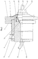
- the hydraulic systems of the machine and the tool are used to solve the task a line connected via a coupling element, one half of which at one Bolt is attached, which is arranged on the arm hydraulically movable forwards and backwards is.
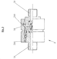
- the second coupling half is attached to the tool at a point on which the first coupling half in the case of hydraulically induced axial movement of the bolt on which it attached is moved towards or away from when the arm and tool are in one position precisely defined by stop surfaces. (Entanglements are in In this sense it is regarded as a special case of stop surfaces.) It becomes a coupling element used to connect the coupling between two hydraulic hoses by a linear one Relative movement of the two coupling halves to one another or closed to one another or can be opened.
- the two coupling halves are aligned and in one Distance from each other that they move by moving the bolt into one of its End positions are connected and the clutch is closed.
- the way of Bolt is at least so long that the two coupling halves are completely disengaged come when the bolt is moved to the other end position.
- the bolt itself with a continuous Provide hole and the part of the hydraulic line belonging to the machine is through this Hole drilled.
- the machine side coupling half is on one side of the hole connected.
- the part of the machine that ends in the machine ends in this coupling half Hydraulic line.
- the one for opening and closing the clutch between the hydraulic systems on the arm and Bolt on the tool is also referred to as a "coupling bolt”.
- This coupling bolt is preferably also used immediately as a fixing bolt, that is to say as that Bolt that engages in a hole in the tool and so together with stop surfaces fixed the relative position of the tool and arm to each other.
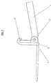
- arm 1 and tool 2 are first brought into the relative position shown in FIG. 1.
- the two parts lie against each other on the hook 5 forming a stop surface against vertical relative movement and on the stop surface 6 acting against horizontal relative movement. They thus assume a precisely defined relative position to one another in the plane lying parallel to the drawing plane. In the direction normal to the plane of the drawing, the relative position of the two parts to one another is defined by two stop surfaces on the tool lying parallel to the plane of the drawing, between which the arm is inserted.
- the two stop surfaces can of course also form a wedge-shaped groove towards the arm.
- the bolt 3 which is mounted in a cylinder on the arm and is hydraulically movable in its axial direction, is extended so that it has a hole in the tool, which in this position aligned with the cylinder, comes into engagement.
- the bolt 3 thus serves as a fixing bolt.
- Hydraulic system hose belonging to the machine through hole 3.1 and on the end of the bolt facing the tool together with a Coupling half can be fixed.
- a slide is attached to each tool and arm, which is movably mounted in the plane normal to the stop surfaces (5, 6) via guide rails or a swivel bearing. If the tool and arm are separated from each other, the slides are held by the action of gravity or a spring and possibly an end stop in such a way that the coupling halves are covered. Protrusions are provided on the tool and arm, which, in the relative movement of the two parts which brings them into abutment on the abutment surfaces (5, 6), touch the slide of the other part and move it so that the coupling halves are exposed. It is also possible to shape and guide the slider on the tool and arm in such a way that the two sliders belonging to the two halves of a coupling touch each other and move them so that the coupling halves are exposed.
Landscapes
- Engineering & Computer Science (AREA)
- Mechanical Engineering (AREA)
- Civil Engineering (AREA)
- Structural Engineering (AREA)
- Life Sciences & Earth Sciences (AREA)
- General Engineering & Computer Science (AREA)
- Mining & Mineral Resources (AREA)
- Soil Sciences (AREA)
- Environmental Sciences (AREA)
- Zoology (AREA)
- Shovels (AREA)
- Automatic Tool Replacement In Machine Tools (AREA)
- Harvester Elements (AREA)
- Agricultural Machines (AREA)
- Lifting Devices For Agricultural Implements (AREA)
- Quick-Acting Or Multi-Walled Pipe Joints (AREA)
Claims (5)
- La fixation d'un outil de l'équipement hydraulique, attaché à un bras d'une machine, qui est équipée avec encore un équipement hydraulique et le attachement de ces deux équipements hydrauliques fait usage decharacterisé en ce queles surfaces de contact au moyens de ces-que le bras (1) et l'outil (2) sont relies,un boulon qui est coulissant avec de moyens hydrauliques qui engrène dans un trou de l'outil (2) et qui est fixé à les bras mentioné etun élément de couplage qui est placé entre les deux parts d'une conduit hydraulique et les deux moitiés de l'élément de couplage sont muniées pour embrayer ou débrayer l'un de l'autre par mouvement relatif linéaire,ce part de l'élément hydraulique étant fixé à la machine dont l'un bout est fermé avec une première moitié (7.1) de l'élément de couplage mentioné est attachée à un boulon (3) qui est coulissant par un cylindre hydraulique (4) au bras (1) mentioné,que la deuxième moitié (7.2) de l'élément de couplage est attachée à l'outil (2) mentioné,que avec cette deuxième moitié mentioné de l'élément de couplage ce part de la conduit hydraulique est attachée qui est un part de 1' equipement hydraulique de l'outil mentioné, etque en ce cas le bras (1) mentioné et l'outil (2) mentioné sont à la position adjointe,la ligne de jonction entre les deux moitiés de l'élément de couplage mentioné est en parallèle à la direction de mouvement de boulon (3) mentioné,les moitiés de l'élément de couplage sont alignées avec les surfaces de couplage vis à vis,la deuxième moitié (7.2) de l'élément de couplage qui est attachée à l'outil (2) mentioné est à cette position relative au cylindre (4) mentioné qui aie la même position que la position du boulon si le boulon etait à une position du bout et la deuxième moitié (7.2) de l'élément de couplage resait fixé en verouillant à la première moitié (7.1) mentionée de l'élément de couplage qui est attachée au boulon (3) mentioné à la position "en barrage" et,que la direction de mouvement du boulon mentioné hors de la position du bout est la même diection de mouvement à laquelle la première moitié (7.1) mentionée de l'élément de couplage qui est en en mouvant pour debrayées les deux moitiés de l'élément de couplage le deuxième moitié étant à une position d'arrêt et,que le cours possible de mouvement coulissant du boulon (3) mentioné est au moins de la même lonqueur que la distance des deux moitiés de l'élément de couplage, s'engrènement à la position d'embrayage, vue en parallèle à la direction de mouvement du boulon mentioné.
- La fixation selon revendication 1, characterisée en ce que le part de conduit hydraulique d'équipement hydraulique de la machine étant part des équipements hydrauliques se conduit à travers d'une perforation alignée (3.1) du boulon (3) mentioné, que l'un des bouts de la perforation est positioné à la face frontale du boulon mentioné, étant vis à vis a l'outil mentioné et que à cette position la première moitié (7.1) de l'élément de couplage hydraulique (7) est attachée au boulon mentioné.
- La fixation selon revendication 2, characterisée en ce que la face frontale du boulon (3) est munie d'une orifice elagi (3.2) comparé à la perforation (3.1) mentioné, que dans l'orifice mentioné la première moitié (7.1) de couplage hydraulique est disposée et l'orifice mentioné (3.2) a une profondeur que la moitié mentioné de couplage hydraulique ne dépasse pas de l'orifice (3.2) mentionée.
- La fixation selon une des revendication précedantes, characterisée en ce que ce boulon mentioné est utilisé comme boulon (3) à lequel la moitié mentioné de couplage hydraulique y est attaché et le boulon (3) mentioné s'étend vers la perforation de l'outil mentioné.
- La fixation selon une des revendication précedantes, characterisée en ce que la moitié mentioné de couplage hydraulique est attaché à l'outil (2) au moyen d'un l'élément élastique relié.
Applications Claiming Priority (3)
| Application Number | Priority Date | Filing Date | Title |
|---|---|---|---|
| AT0136195A AT402648B (de) | 1995-08-11 | 1995-08-11 | Befestigung eines werkzeuges an der befestigung eines werkzeuges an der ladeschwinge einer fahrbaren arbeitsmaschine ladeschwinge einer fahrbaren arbeitsmaschine |
| AT136195 | 1995-08-11 | ||
| AT1361/95 | 1995-08-11 |
Publications (2)
| Publication Number | Publication Date |
|---|---|
| EP0758552A1 EP0758552A1 (fr) | 1997-02-19 |
| EP0758552B1 true EP0758552B1 (fr) | 2002-06-12 |
Family
ID=3512227
Family Applications (1)
| Application Number | Title | Priority Date | Filing Date |
|---|---|---|---|
| EP96112920A Expired - Lifetime EP0758552B1 (fr) | 1995-08-11 | 1996-08-11 | Fixation d'un outil au bras d'un engin de chantier |
Country Status (3)
| Country | Link |
|---|---|
| EP (1) | EP0758552B1 (fr) |
| AT (2) | AT402648B (fr) |
| DE (2) | DE29613836U1 (fr) |
Families Citing this family (2)
| Publication number | Priority date | Publication date | Assignee | Title |
|---|---|---|---|---|
| AT411839B (de) * | 2001-09-28 | 2004-06-25 | Puehringer Josef Ing Mag | Frontlader |
| DE102004054058B3 (de) * | 2004-11-05 | 2005-12-15 | Lehnhoff Hartstahl Gmbh & Co | Hydraulikkupplung mit Reinigungseinrichtung |
Family Cites Families (6)
| Publication number | Priority date | Publication date | Assignee | Title |
|---|---|---|---|---|
| AT264369B (de) * | 1966-08-26 | 1968-08-26 | Erich Birgmayer | Kupplung zum Anschließen der zu den Hubzylindern eines abstellbaren Frontladers führenden Hydraulikleitung an die Hydraulikanlage eines Ackerschleppers |
| DE2856556C2 (de) * | 1978-12-28 | 1980-10-23 | Liebherr-Hydraulikbagger Gmbh, 7951 Kirchdorf | Werkzeugaufhängung für hydraulisch betätigbare auswechselbare Werkzeuge |
| WO1981000295A1 (fr) * | 1979-07-25 | 1981-02-05 | Sabco Ltd | Fluide de deconnexion sensible a la pression. vanne d'accouplement et de coupure |
| US5108252A (en) * | 1988-04-04 | 1992-04-28 | Gilmore Transportation Services, Inc. | Quick-disconnect coupling for a machine having a boom and a stick |
| SE463319B (sv) * | 1989-07-18 | 1990-11-05 | John Teodor Sonerud | Koppling av drivsystem till ett arbetsredskap paa en graevmaskin eller liknande |
| SE467742B (sv) * | 1991-09-06 | 1992-09-07 | Sonerud John Teodor | Anordning foer snabbkoppling av ett redskap till en graevmaskin med samtidig anslutning till ett drivsystem |
-
1995
- 1995-08-11 AT AT0136195A patent/AT402648B/de not_active IP Right Cessation
-
1996
- 1996-08-09 DE DE29613836U patent/DE29613836U1/de not_active Expired - Lifetime
- 1996-08-11 AT AT96112920T patent/ATE219193T1/de active
- 1996-08-11 EP EP96112920A patent/EP0758552B1/fr not_active Expired - Lifetime
- 1996-08-11 DE DE59609318T patent/DE59609318D1/de not_active Expired - Lifetime
Also Published As
| Publication number | Publication date |
|---|---|
| AT402648B (de) | 1997-07-25 |
| ATA136195A (de) | 1996-11-15 |
| EP0758552A1 (fr) | 1997-02-19 |
| ATE219193T1 (de) | 2002-06-15 |
| DE59609318D1 (de) | 2002-07-18 |
| DE29613836U1 (de) | 1996-10-02 |
Similar Documents
| Publication | Publication Date | Title |
|---|---|---|
| DE3426892C2 (fr) | ||
| DE3312442C2 (de) | Schnellwechselvorrichtung für Arbeitswerkzeuge an einem Baggerausleger | |
| EP1624116B1 (fr) | Attache rapide hydraulique | |
| DE69717080T2 (de) | Einrichtung zum verbinden eines hydraulischen werkzeuges mit einer arbeitsmaschine | |
| DE2940916C2 (de) | Mit Greiffingern versehener Greifer für Manipulatoren | |
| DE3102250A1 (de) | Vorrichtung zur automatischen aufnahme von werkzeugen, insbesondere fuer bagger, ladefahrzeuge und andere erdbewegungsmaschinen | |
| EP2159333B1 (fr) | Accouplement pour support d'énergie et accouplement doté d'un accouplement pour support d'énergie | |
| DE102005037105C5 (de) | Adapter für ein Arbeitsgerät als Teil einer Schnellwechselvorrichtung und Schnellwechselvorrichtung | |
| EP1727946B1 (fr) | Dispositif de changement rapide comprenant un couplage hydraulique pour des supports situes sur un appareil de construction | |
| EP4200479B1 (fr) | Unité à changement rapide et système à changement rapide | |
| EP3502357B1 (fr) | Dispositif de changement rapide | |
| DE2640840C2 (fr) | ||
| EP1388616A1 (fr) | Dispositif pour accoupler et découpler les embouts de conduites d'alimentation en fluide | |
| EP0674053A2 (fr) | Accouplement rapide d'un accessoire à une pelle mécanique | |
| EP0758552B1 (fr) | Fixation d'un outil au bras d'un engin de chantier | |
| DE29702648U1 (de) | Vorrichtung zur Ver- und Entriegelung eines Werkzeugs an einem Werkzeug-Aufnahmerahmen von Kompaktladern | |
| EP2152974B1 (fr) | Accouplement pour machines de travail | |
| AT411839B (de) | Frontlader | |
| DE2856039C2 (de) | Kupplungsvorrichtung zum Anbringen eines Arbeitsgeräts am Ausleger eines Fahrzeugs | |
| DE3008819A1 (de) | Steuermechanismus fuer ein fahrzeug | |
| DE19611873C2 (de) | Vorrichtung zum Verbinden von Gehäuseteilen für elektrische Steckverbindungen | |
| DE3518581A1 (de) | Werkzeugwechseleinrichtung | |
| DE102009003516A1 (de) | Automatische Greiferkopplung | |
| EP4353910B1 (fr) | Machine de travail avec dispositif d'accouplement pour conduites transportant des fluides et procédé pour établir un état de fonctionnement d'une machine de travail | |
| DE102006049059A1 (de) | Hydraulischer Schnellwechsler |
Legal Events
| Date | Code | Title | Description |
|---|---|---|---|
| PUAI | Public reference made under article 153(3) epc to a published international application that has entered the european phase |
Free format text: ORIGINAL CODE: 0009012 |
|
| AK | Designated contracting states |
Kind code of ref document: A1 Designated state(s): AT DE DK FR GB IT NL SE |
|
| AX | Request for extension of the european patent |
Free format text: SI PAYMENT 960903 |
|
| RHK1 | Main classification (correction) |
Ipc: E02F 3/36 |
|
| K1C1 | Correction of patent application (title page) published |
Effective date: 19970219 |
|
| 17P | Request for examination filed |
Effective date: 19970819 |
|
| GRAG | Despatch of communication of intention to grant |
Free format text: ORIGINAL CODE: EPIDOS AGRA |
|
| 17Q | First examination report despatched |
Effective date: 20010813 |
|
| GRAG | Despatch of communication of intention to grant |
Free format text: ORIGINAL CODE: EPIDOS AGRA |
|
| GRAH | Despatch of communication of intention to grant a patent |
Free format text: ORIGINAL CODE: EPIDOS IGRA |
|
| GRAH | Despatch of communication of intention to grant a patent |
Free format text: ORIGINAL CODE: EPIDOS IGRA |
|
| GRAA | (expected) grant |
Free format text: ORIGINAL CODE: 0009210 |
|
| AK | Designated contracting states |
Kind code of ref document: B1 Designated state(s): AT DE DK FR GB IT NL SE |
|
| AX | Request for extension of the european patent |
Free format text: SI PAYMENT 19960903 |
|
| PG25 | Lapsed in a contracting state [announced via postgrant information from national office to epo] |
Ref country code: NL Free format text: LAPSE BECAUSE OF FAILURE TO SUBMIT A TRANSLATION OF THE DESCRIPTION OR TO PAY THE FEE WITHIN THE PRESCRIBED TIME-LIMIT Effective date: 20020612 |
|
| REF | Corresponds to: |
Ref document number: 219193 Country of ref document: AT Date of ref document: 20020615 Kind code of ref document: T |
|
| REG | Reference to a national code |
Ref country code: GB Ref legal event code: FG4D Free format text: NOT ENGLISH |
|
| REF | Corresponds to: |
Ref document number: 59609318 Country of ref document: DE Date of ref document: 20020718 |
|
| PG25 | Lapsed in a contracting state [announced via postgrant information from national office to epo] |
Ref country code: DK Free format text: LAPSE BECAUSE OF FAILURE TO SUBMIT A TRANSLATION OF THE DESCRIPTION OR TO PAY THE FEE WITHIN THE PRESCRIBED TIME-LIMIT Effective date: 20020912 |
|
| GBT | Gb: translation of ep patent filed (gb section 77(6)(a)/1977) |
Effective date: 20020918 |
|
| NLV1 | Nl: lapsed or annulled due to failure to fulfill the requirements of art. 29p and 29m of the patents act | ||
| ET | Fr: translation filed | ||
| PLBE | No opposition filed within time limit |
Free format text: ORIGINAL CODE: 0009261 |
|
| STAA | Information on the status of an ep patent application or granted ep patent |
Free format text: STATUS: NO OPPOSITION FILED WITHIN TIME LIMIT |
|
| 26N | No opposition filed |
Effective date: 20030313 |
|
| PG25 | Lapsed in a contracting state [announced via postgrant information from national office to epo] |
Ref country code: IT Free format text: LAPSE BECAUSE OF NON-PAYMENT OF DUE FEES;WARNING: LAPSES OF ITALIAN PATENTS WITH EFFECTIVE DATE BEFORE 2007 MAY HAVE OCCURRED AT ANY TIME BEFORE 2007. THE CORRECT EFFECTIVE DATE MAY BE DIFFERENT FROM THE ONE RECORDED. Effective date: 20050811 |
|
| PGFP | Annual fee paid to national office [announced via postgrant information from national office to epo] |
Ref country code: SE Payment date: 20100817 Year of fee payment: 15 Ref country code: FR Payment date: 20100908 Year of fee payment: 15 Ref country code: AT Payment date: 20100930 Year of fee payment: 15 |
|
| PGFP | Annual fee paid to national office [announced via postgrant information from national office to epo] |
Ref country code: GB Payment date: 20100818 Year of fee payment: 15 |
|
| PGFP | Annual fee paid to national office [announced via postgrant information from national office to epo] |
Ref country code: DE Payment date: 20100928 Year of fee payment: 15 |
|
| REG | Reference to a national code |
Ref country code: SE Ref legal event code: EUG |
|
| GBPC | Gb: european patent ceased through non-payment of renewal fee |
Effective date: 20110811 |
|
| REG | Reference to a national code |
Ref country code: FR Ref legal event code: ST Effective date: 20120430 |
|
| PG25 | Lapsed in a contracting state [announced via postgrant information from national office to epo] |
Ref country code: GB Free format text: LAPSE BECAUSE OF NON-PAYMENT OF DUE FEES Effective date: 20110811 Ref country code: FR Free format text: LAPSE BECAUSE OF NON-PAYMENT OF DUE FEES Effective date: 20110831 |
|
| REG | Reference to a national code |
Ref country code: AT Ref legal event code: MM01 Ref document number: 219193 Country of ref document: AT Kind code of ref document: T Effective date: 20110811 |
|
| PG25 | Lapsed in a contracting state [announced via postgrant information from national office to epo] |
Ref country code: AT Free format text: LAPSE BECAUSE OF NON-PAYMENT OF DUE FEES Effective date: 20110811 |
|
| PG25 | Lapsed in a contracting state [announced via postgrant information from national office to epo] |
Ref country code: SE Free format text: LAPSE BECAUSE OF NON-PAYMENT OF DUE FEES Effective date: 20110812 |
|
| PG25 | Lapsed in a contracting state [announced via postgrant information from national office to epo] |
Ref country code: DE Free format text: LAPSE BECAUSE OF NON-PAYMENT OF DUE FEES Effective date: 20130301 |
|
| REG | Reference to a national code |
Ref country code: DE Ref legal event code: R119 Ref document number: 59609318 Country of ref document: DE Effective date: 20130301 |