EP0758552B1 - Coupling of an implement to the loading arm of a construction machine - Google Patents
Coupling of an implement to the loading arm of a construction machine Download PDFInfo
- Publication number
- EP0758552B1 EP0758552B1 EP96112920A EP96112920A EP0758552B1 EP 0758552 B1 EP0758552 B1 EP 0758552B1 EP 96112920 A EP96112920 A EP 96112920A EP 96112920 A EP96112920 A EP 96112920A EP 0758552 B1 EP0758552 B1 EP 0758552B1
- Authority
- EP
- European Patent Office
- Prior art keywords
- coupling
- bolt
- tool
- hydraulic
- attached
- Prior art date
- Legal status (The legal status is an assumption and is not a legal conclusion. Google has not performed a legal analysis and makes no representation as to the accuracy of the status listed.)
- Expired - Lifetime
Links
- 230000008878 coupling Effects 0.000 title claims abstract description 70
- 238000010168 coupling process Methods 0.000 title claims abstract description 70
- 238000005859 coupling reaction Methods 0.000 title claims abstract description 70
- 238000010276 construction Methods 0.000 title description 2
- 230000009471 action Effects 0.000 abstract description 2
- 230000008859 change Effects 0.000 description 5
- 238000000034 method Methods 0.000 description 3
- 230000005489 elastic deformation Effects 0.000 description 2
- 239000012530 fluid Substances 0.000 description 2
- 241001136792 Alle Species 0.000 description 1
- 230000000694 effects Effects 0.000 description 1
- 239000013013 elastic material Substances 0.000 description 1
- 239000004744 fabric Substances 0.000 description 1
- 230000005484 gravity Effects 0.000 description 1
- 239000002655 kraft paper Substances 0.000 description 1
- 239000000463 material Substances 0.000 description 1
- 230000007246 mechanism Effects 0.000 description 1
- 239000002184 metal Substances 0.000 description 1
- 230000008569 process Effects 0.000 description 1
- 230000001681 protective effect Effects 0.000 description 1
- 239000007787 solid Substances 0.000 description 1
Images
Classifications
-
- A—HUMAN NECESSITIES
- A01—AGRICULTURE; FORESTRY; ANIMAL HUSBANDRY; HUNTING; TRAPPING; FISHING
- A01B—SOIL WORKING IN AGRICULTURE OR FORESTRY; PARTS, DETAILS, OR ACCESSORIES OF AGRICULTURAL MACHINES OR IMPLEMENTS, IN GENERAL
- A01B59/00—Devices specially adapted for connection between animals or tractors and agricultural machines or implements
- A01B59/002—Details, component parts
-
- E—FIXED CONSTRUCTIONS
- E02—HYDRAULIC ENGINEERING; FOUNDATIONS; SOIL SHIFTING
- E02F—DREDGING; SOIL-SHIFTING
- E02F3/00—Dredgers; Soil-shifting machines
- E02F3/04—Dredgers; Soil-shifting machines mechanically-driven
- E02F3/28—Dredgers; Soil-shifting machines mechanically-driven with digging tools mounted on a dipper- or bucket-arm, i.e. there is either one arm or a pair of arms, e.g. dippers, buckets
- E02F3/36—Component parts
- E02F3/3604—Devices to connect tools to arms, booms or the like
- E02F3/3609—Devices to connect tools to arms, booms or the like of the quick acting type, e.g. controlled from the operator seat
- E02F3/3631—Devices to connect tools to arms, booms or the like of the quick acting type, e.g. controlled from the operator seat with a hook and a transversal locking element
-
- E—FIXED CONSTRUCTIONS
- E02—HYDRAULIC ENGINEERING; FOUNDATIONS; SOIL SHIFTING
- E02F—DREDGING; SOIL-SHIFTING
- E02F3/00—Dredgers; Soil-shifting machines
- E02F3/04—Dredgers; Soil-shifting machines mechanically-driven
- E02F3/28—Dredgers; Soil-shifting machines mechanically-driven with digging tools mounted on a dipper- or bucket-arm, i.e. there is either one arm or a pair of arms, e.g. dippers, buckets
- E02F3/36—Component parts
- E02F3/3604—Devices to connect tools to arms, booms or the like
- E02F3/3609—Devices to connect tools to arms, booms or the like of the quick acting type, e.g. controlled from the operator seat
- E02F3/3654—Devices to connect tools to arms, booms or the like of the quick acting type, e.g. controlled from the operator seat with energy coupler, e.g. coupler for hydraulic or electric lines, to provide energy to drive(s) mounted on the tool
-
- E—FIXED CONSTRUCTIONS
- E02—HYDRAULIC ENGINEERING; FOUNDATIONS; SOIL SHIFTING
- E02F—DREDGING; SOIL-SHIFTING
- E02F3/00—Dredgers; Soil-shifting machines
- E02F3/04—Dredgers; Soil-shifting machines mechanically-driven
- E02F3/28—Dredgers; Soil-shifting machines mechanically-driven with digging tools mounted on a dipper- or bucket-arm, i.e. there is either one arm or a pair of arms, e.g. dippers, buckets
- E02F3/36—Component parts
- E02F3/3604—Devices to connect tools to arms, booms or the like
- E02F3/3609—Devices to connect tools to arms, booms or the like of the quick acting type, e.g. controlled from the operator seat
- E02F3/3663—Devices to connect tools to arms, booms or the like of the quick acting type, e.g. controlled from the operator seat hydraulically-operated
Definitions
- the invention relates to the releasable attachment of a hydraulically actuated tool to an arm of a machine equipped with a hydraulic system.
- the invention is particularly good for machines such as tractors or mobile construction machinery.
- tools a plow, an excavator shovel or a gripper tongs are particularly important.
- the arm of the machine is movably mounted on it and can be operated by means of hydraulics.
- Such an attachment is disclosed in DE-A-2856556.
- the tool and arm are first brought into a precisely defined position in a vertical plane via a hook and a stop surface in the vertical process.
- the fastening is then fixed with the help of bolts which are normally movably mounted on this level in the arm by pushing these bolts into bores in the tool - which in this position are aligned with the mounting of the bolts in the arm.
- the bolts used to fix the tool on the arm are also called fixation bolts.
- fixation bolts In the direction normal to the fixing bolts and bores, and thus to the first-mentioned plane, the tool and arm are fixed relative to one another with a little play via stop faces.
- This quick-change system like all currently known quick-change systems, only fixes the tool to the arm.
- the connection between the hydraulic system of the machine and any existing hydraulic system of the tool is not established.
- This connection that is to say the plugging together of coupling elements on hydraulic hoses on the arm with coupling elements on hydraulic hoses on the tool, must be carried out by hand, that is to say by handling the arm-tool connection area. The person operating the machine must therefore leave the driver's cab for this purpose or a second person must be consulted.
- the object of the invention is to establish the connection between the Execute the hydraulic system of the machine and the hydraulic system of the tool so that they can be manufactured and solved from the machine's cab.
- the hydraulic systems of the machine and the tool are used to solve the task a line connected via a coupling element, one half of which at one Bolt is attached, which is arranged on the arm hydraulically movable forwards and backwards is.
- the second coupling half is attached to the tool at a point on which the first coupling half in the case of hydraulically induced axial movement of the bolt on which it attached is moved towards or away from when the arm and tool are in one position precisely defined by stop surfaces. (Entanglements are in In this sense it is regarded as a special case of stop surfaces.) It becomes a coupling element used to connect the coupling between two hydraulic hoses by a linear one Relative movement of the two coupling halves to one another or closed to one another or can be opened.
- the two coupling halves are aligned and in one Distance from each other that they move by moving the bolt into one of its End positions are connected and the clutch is closed.
- the way of Bolt is at least so long that the two coupling halves are completely disengaged come when the bolt is moved to the other end position.
- the bolt itself with a continuous Provide hole and the part of the hydraulic line belonging to the machine is through this Hole drilled.
- the machine side coupling half is on one side of the hole connected.
- the part of the machine that ends in the machine ends in this coupling half Hydraulic line.
- the one for opening and closing the clutch between the hydraulic systems on the arm and Bolt on the tool is also referred to as a "coupling bolt”.
- This coupling bolt is preferably also used immediately as a fixing bolt, that is to say as that Bolt that engages in a hole in the tool and so together with stop surfaces fixed the relative position of the tool and arm to each other.
- arm 1 and tool 2 are first brought into the relative position shown in FIG. 1.
- the two parts lie against each other on the hook 5 forming a stop surface against vertical relative movement and on the stop surface 6 acting against horizontal relative movement. They thus assume a precisely defined relative position to one another in the plane lying parallel to the drawing plane. In the direction normal to the plane of the drawing, the relative position of the two parts to one another is defined by two stop surfaces on the tool lying parallel to the plane of the drawing, between which the arm is inserted.
- the two stop surfaces can of course also form a wedge-shaped groove towards the arm.
- the bolt 3 which is mounted in a cylinder on the arm and is hydraulically movable in its axial direction, is extended so that it has a hole in the tool, which in this position aligned with the cylinder, comes into engagement.
- the bolt 3 thus serves as a fixing bolt.
- Hydraulic system hose belonging to the machine through hole 3.1 and on the end of the bolt facing the tool together with a Coupling half can be fixed.
- a slide is attached to each tool and arm, which is movably mounted in the plane normal to the stop surfaces (5, 6) via guide rails or a swivel bearing. If the tool and arm are separated from each other, the slides are held by the action of gravity or a spring and possibly an end stop in such a way that the coupling halves are covered. Protrusions are provided on the tool and arm, which, in the relative movement of the two parts which brings them into abutment on the abutment surfaces (5, 6), touch the slide of the other part and move it so that the coupling halves are exposed. It is also possible to shape and guide the slider on the tool and arm in such a way that the two sliders belonging to the two halves of a coupling touch each other and move them so that the coupling halves are exposed.
Landscapes
- Engineering & Computer Science (AREA)
- Mechanical Engineering (AREA)
- Civil Engineering (AREA)
- Structural Engineering (AREA)
- Life Sciences & Earth Sciences (AREA)
- General Engineering & Computer Science (AREA)
- Mining & Mineral Resources (AREA)
- Soil Sciences (AREA)
- Environmental Sciences (AREA)
- Zoology (AREA)
- Shovels (AREA)
- Automatic Tool Replacement In Machine Tools (AREA)
- Harvester Elements (AREA)
- Agricultural Machines (AREA)
- Lifting Devices For Agricultural Implements (AREA)
- Quick-Acting Or Multi-Walled Pipe Joints (AREA)
Abstract
Description
Die Erfindung betrifft die lösbare Befestigung eines hydraulisch betätigbaren Werkzeuges an
einem Arm einer mit einer Hydraulikanlage ausgerüsteten Maschine.
Die Erfindung ist insbesondere gut für Maschinen wie Traktoren oder fahrbaren Baumaschinen
anzuwenden. Bei "Werkzeug" ist insbesondere an einen Pflug, eine Baggerschaufel oder eine
Greiferzange zu denken. Im Normalfall ist der Arm der Maschine an dieser beweglich gelagert
und mittels Hydraulik betätigbar. Eine derartige Befestigung ist in der DE-A-2856556 offenbart.
Wenn das Werkzeug an dem Arm mit Hilfe einer des weiteren als "Schnellwechselsystem"
bezeichneten Befestigung fixiert ist, kann die Person, welche die Maschine steuert, das Befestigen
und Lösen des Werkzeuges mit Hilfe der hydraulischen Steuerung vom Führerstand aus
durchführen ohne im Berührungsbereich Arm-Werkzeug hantieren zu müssen. Bei einem hier
beispielhaft angeführten, weit verbreiteten Schnellwechselsystem werden beim
Befestigungsvorgang zuerst Werkzeug und Arm über eine Verhakung und eine Anschlagfläche in
einer vertikalen Ebene in eine genau definierte Lage zueinander gebracht. Anschließend wird die
Befestigung mit Hilfe von Bolzen, welche in dem Arm, normal auf diese Ebene beweglich
gelagert sind, fixiert indem diese Bolzen in Bohrungen am Werkzeug - welche bei dieser Lage mit
der Lagerung der Bolzen in dem Arm fluchten - eingeschoben werden. Die zur Fixierung des
Werkzeuges an dem Arm dienenden Bolzen werden des weiteren Fixierbolzen genannt. In der auf
die Fixierbolzen und Bohrungen parallel, und damit auf die zuerst genannte Ebene normal
verlaufenden Richtung sind Werkzeug und Arm mit etwas Spiel über Anschlagflächen relativ
zueinander festgelegt.
Dieses Schnellwechselsystem stellt, wie alle zur Zeit bekannten Schnellwechselsysteme, nur die
Fixierung des Werkzeuges an dem Arm her. Nicht hergestellt wird die Verbindung der
Hydraulikanlage der Maschine mit einer eventuell vorhandenen Hydraulikanlage des Werkzeuges.
Diese Verbindung, also das Zusammenstecken von Kupplungselementen an Hydraulikschläuchen
an dem Arm mit Kupplungselementen an Hydraulikschläuchen am Werkzeug muß von Hand aus,
also doch durch Hantieren im Verbindungsbereich Arm-Werkzeug erfolgen. Die, die Maschine
betätigende Person muß also dafür den Führerstand verlassen oder es muß eine zweite Person
hinzugezogen werden.The invention relates to the releasable attachment of a hydraulically actuated tool to an arm of a machine equipped with a hydraulic system.
The invention is particularly good for machines such as tractors or mobile construction machinery. In the case of "tools", a plow, an excavator shovel or a gripper tongs are particularly important. Normally, the arm of the machine is movably mounted on it and can be operated by means of hydraulics. Such an attachment is disclosed in DE-A-2856556.
If the tool is fixed to the arm by means of a fastening, also referred to as a "quick change system", the person who controls the machine can carry out the fastening and loosening of the tool by means of the hydraulic control from the driver's cab without in the contact area of the arm tool to have to handle In a widely used quick-change system, which is exemplified here, the tool and arm are first brought into a precisely defined position in a vertical plane via a hook and a stop surface in the vertical process. The fastening is then fixed with the help of bolts which are normally movably mounted on this level in the arm by pushing these bolts into bores in the tool - which in this position are aligned with the mounting of the bolts in the arm. The bolts used to fix the tool on the arm are also called fixation bolts. In the direction normal to the fixing bolts and bores, and thus to the first-mentioned plane, the tool and arm are fixed relative to one another with a little play via stop faces.
This quick-change system, like all currently known quick-change systems, only fixes the tool to the arm. The connection between the hydraulic system of the machine and any existing hydraulic system of the tool is not established. This connection, that is to say the plugging together of coupling elements on hydraulic hoses on the arm with coupling elements on hydraulic hoses on the tool, must be carried out by hand, that is to say by handling the arm-tool connection area. The person operating the machine must therefore leave the driver's cab for this purpose or a second person must be consulted.
Die der Erfindung zu Grunde liegende Aufgabe besteht darin, die Verbindung zwischen der Hydraulikanlage der Maschine und der Hydraulikanlage des Werkzeuges so auszuführen, daß sie vom Führerstand der Maschine aus hergestellt und gelöst werden kann.The object of the invention is to establish the connection between the Execute the hydraulic system of the machine and the hydraulic system of the tool so that they can be manufactured and solved from the machine's cab.
Zur Lösung der Aufgabe werden die Hydraulikanlagen der Maschine und des Werkzeuges mittels einer Leitung über ein Kupplungselement in Verbindung gebracht, dessen eine Hälfte an einem Bolzen befestigt ist, welcher am Arm hydraulisch vorwärts und rückwärts beweglich angeordnet ist. Die zweite Kupplungshälfte ist am Werkzeug an einer Stelle befestigt, auf welche sich die erste Kupplungshälfte bei hydraulisch hervorgerufener Axialbewegung des Bolzens an dem sie befestigt ist hin bewegt bzw. von der sie sich weg bewegt, wenn sich Arm und Werkzeug in einer durch Anschlagflächen zueinander genau definierten Lage befinden. (Verhakungen werden in diesem Sinn als Spezialfall von Anschlagflächen angesehen.) Es wird ein Kupplungselement verwendet, mit dem die Kupplung zwischen zwei Hydraulikschläuchen durch eine lineare Relativbewegung der beiden Kupplungshälften zueinander bzw. voneinander geschlossen bzw. geöffnet werden kann. Die beiden Kupplungshälften sind so ausgerichtet und in einer solchen Entfernung voneinander angeordnet, daß sie durch die Bewegung des Bolzens in eine seiner Endstellungen verbunden werden und damit die Kupplung geschlossen wird. Der Weg des Bolzens ist mindestens so lang, daß die beiden Kupplungshälften vollkommen außer Eingriff kommen wenn der Bolzen in die andere Endstellung bewegt wird.The hydraulic systems of the machine and the tool are used to solve the task a line connected via a coupling element, one half of which at one Bolt is attached, which is arranged on the arm hydraulically movable forwards and backwards is. The second coupling half is attached to the tool at a point on which the first coupling half in the case of hydraulically induced axial movement of the bolt on which it attached is moved towards or away from when the arm and tool are in one position precisely defined by stop surfaces. (Entanglements are in In this sense it is regarded as a special case of stop surfaces.) It becomes a coupling element used to connect the coupling between two hydraulic hoses by a linear one Relative movement of the two coupling halves to one another or closed to one another or can be opened. The two coupling halves are aligned and in one Distance from each other that they move by moving the bolt into one of its End positions are connected and the clutch is closed. The way of Bolt is at least so long that the two coupling halves are completely disengaged come when the bolt is moved to the other end position.
Entsprechend einer vorteilhaften Ausführung wird der Bolzen selbst mit einer durchgehenden Bohrung versehen und der zur Maschine gehörenden Teil der Hydraulikleitung wird durch diese Bohrung verlegt. An einer Seite der Bohrung ist die maschinenseitige Kupplungshälfte angeschlossen. In dieser Kupplungshälfte endet der zur Maschine gehörende Teil der Hydraulikleitung.According to an advantageous embodiment, the bolt itself with a continuous Provide hole and the part of the hydraulic line belonging to the machine is through this Hole drilled. The machine side coupling half is on one side of the hole connected. The part of the machine that ends in the machine ends in this coupling half Hydraulic line.
Der zum Öffnen und Schließen der Kupplung zwischen den Hydraulikanlagen an dem Arm und am Werkzeug dienende Bolzen wird des weiteren als "Kupplungsbolzen" bezeichnet. Vorzugsweise wird dieser Kupplungsbolzen auch gleich als Fixierbolzen verwendet, also als jener Bolzen, welcher in eine Bohrung am Werkzeug eingreift und so gemeinsam mit Anschlagflächen die Relativlage von Werkzeug und Arm zueinander fixiert.The one for opening and closing the clutch between the hydraulic systems on the arm and Bolt on the tool is also referred to as a "coupling bolt". This coupling bolt is preferably also used immediately as a fixing bolt, that is to say as that Bolt that engages in a hole in the tool and so together with stop surfaces fixed the relative position of the tool and arm to each other.
Die Erfindung wird anhand der folgenden Prinzipzeichnungen anschaulicher:
- Fig. 1
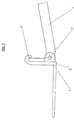
- zeigt die Befestigung eines Werkzeuges an einem Arm mit Hilfe eines sog. Schnellwechselsystems. Da dabei auf die Darstellung von Teilen der Hydraulikanlage verzichtet wurde, gilt Fig. 1 sowohl für die vorbekannte Befestigungsmethode als auch für die Befestigungsmethode entsprechend der vorliegenden Anmeldung.
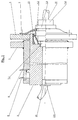
- Fig. 2
- zeigt eine Teilschnittansicht einer erfindungsgemäßen Ausführung einer Befestigung bei der ein mit einer Bohrung versehener Kupplungsbolzen verwendet wird in geschlossenem Zustand. Die Schnittebene liegt parallel zur Achse des Bolzens. Das Kupplungselement ist nur symbolisiert dargestellten. Die Hydraulikflüssigkeit ist nicht dargestellt.
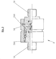
- Fig. 3
- zeigt den prinzipiellen Aufbau des Kupplungselementes von Fig. 2 in einer achsparallelen Teilschnittansicht vergrößert.
- Fig. 1
- shows the attachment of a tool to an arm using a so-called quick-change system. Since parts of the hydraulic system have been omitted, FIG. 1 applies both to the previously known fastening method and to the fastening method according to the present application.
- Fig. 2
- shows a partial sectional view of an embodiment of a fastening according to the invention in which a coupling bolt provided with a bore is used in the closed state. The cutting plane is parallel to the axis of the bolt. The coupling element is only shown symbolized. The hydraulic fluid is not shown.
- Fig. 3
- shows the basic structure of the coupling element of FIG. 2 in an axially parallel partial sectional view enlarged.
Zum Herstellen der Verbindung werden Arm 1 und Werkzeug 2 zuerst in die in Fig. 1
dargestellte Relativlage zueinander gebracht. Dabei liegen die beiden Teile an der eine
Anschlagfläche gegen vertikale Relativbewegung bildenden Verhakung 5 und an der gegen
horizontale Relativbewegung wirkenden Anschlagfläche 6 aneinander an. Sie nehmen damit in
der zur Zeichenebene parallel liegenden Ebene eine genau definierte Relativlage zueinander ein.
In der auf die Zeichenebene normal stehenden Richtung wird die Relativlage der beiden Teile
zueinander durch zwei zur Zeichenebene parallel liegende Anschlagflächen am Werkzeug
zwischen denen der Arm eingesteckt wird, definiert. (Die beiden Anschlagflächen können
natürlich auch eine sich keilförmig zum Arm hin erweiternde Nut bilden.) Nun wird der in einem
Zylinder an dem Arm gelagerte, hydraulisch in seiner Achsrichtung bewegliche Bolzens 3
ausgefahren, sodaß er mit einer Bohrung am Werkzeug, welche bei dieser Lage mit dem Zylinder
fluchtet, in Eingriff kommt. Damit ist die Relativlage zwischen Arm und Werkzeug nicht nur
definiert sondern auch fixiert. Der Bolzen 3 dient somit als Fixierbolzen.
Nachdem sich Werkzeug und Arm in einer durch Anschlagflächen 5,6 zueinander genau
definierten Lage befinden wird erfindungsgemäß ein hydraulisch beweglicher Bolzen, der sog.
Kupplungsbolzen, an welchem das mit einer Kupplungshälfte versehene Ende des
maschinenseitigen Teiles der Hydraulik-Verbindungsleitung befestigt ist, vom Arm aus auf das
Werkzeug zu bewegt. Die zweite Kupplungshälfte ist am Werkzeug so angeordnet, daß dabei die
Hydraulikkupplung geschlossen wird.To establish the connection, arm 1 and
After the tool and arm are in a position precisely defined by
Fig. 2 zeigt eine Ausführung bei der die Hydraulikleitung durch den Kupplungsbolzen verläuft
und obendrein die Funktionen des Kupplungsbolzens und des Fixierbolzen in einem einzigen
Bolzen 3 vereint sind. Bei einer Ausführungsform gemäß Fig. 2 werden die Fixierung des
Werkzeuges 2 an dem Arm 1 und der Anschluß der Hydraulikanlage des Werkzeuges an die
Hydraulikanlage der Maschine mit einem einzigen Arbeitsschritt, nämlich dem Ausfahren des
Bolzens 3 aus dem am Arm 1 befindlichen Zylinder 4 auf das Werkzeug zu, bewirkt.
Der Bolzen 3 kann durch die Hydraulikanlage der Maschine über die Anschlüsse 8 im Zylinder 4
in seiner Achsrichtung vor- und zurück bewegt werden. Der Bolzen weist eine durchgehende
Bohrung 3.1 auf an deren einem Ende sich der Anschluß 10 zu der Hydraulikanlage der Maschine
hin befindet. Am zweiten Ende der Bohrung 3.1, welche sich an der dem Werkzeug zugewandten
Stirnseite des Bolzens befindet, ist die männliche Kupplungshälfte 7.1 der Hydraulikkupplung für
die Verbindung zur Hydraulikanlage des Werkzeuges angebracht. Die weibliche Kupplungshälfte
ist über das elastische Verbindungselement 9 und den zum Kupplungselement gehörenden
Arretierungsring 7.3 am Werkzeug befestigt. Die Kupplungshälften sind mit ihren Achsen
fluchtend zur Achse des Bolzens 3 und der darin befindlichen Bohrung 3.1 ausgerichtet. An der
weiblichen Kupplungshälfte befindet sich der Anschluß 11 zur Hydraulikanlage des Werkzeuges.
Die für das Verständnis der Erfindung wesentlichsten Funktionen des Kupplungselementes sind:
(siehe auch Fig. 3)
- Bei geöffneter Kupplung wird durch jede der Kupplungshälften jene Hydraulikleitung an deren Ende die Kupplungshälfte angebracht ist, abgedichtet.
- Die Kupplung kann nicht in Folge von Kräften zwischen den beiden Teilen des Kupplungselementes, welche starr mit den Enden der beiden zu verbindenden Leitungen verbunden sind, geöffnet werden.
- Die Kupplung kann durch eine Druckkraft, welche in Achsrichtung zwischen dem mit der weiblichen Kupplungshälfte 7.2 elastisch verbundenen Arretierungsring 7.3 und der männlichen Kupplungshälfte 7.1 wirkt, geschlossen werden.
- Die Kupplung kann durch eine Zugkraft, welche in Achsrichtung zwischen Arretierungsring 7.3 und männlicher Kupplungshälfte 7.1 wirkt, geöffnet werden.
- Ein Schnappmechanismus bewirkt, daß beim Schließen der Kupplung die Kupplungshälften zueinander in die Stellung "geschlossen" einrasten und das zum Öffnen der Kupplung ein bestimmtes Kraftniveau, welches der Öffnungsbewegung entgegenwirkt, überwunden werden muß.
- Eine voll- bzw. hohlkegelförmige Abschrägung 7.1.1 bzw. 7.2.1 an der, der jeweils anderen Kupplungshälfte zugewandten Stirnseite der beiden Kupplungshälften erleichtert das Zusammenführen der beiden Kupplungshälften.
Das vorzugsweise elastische Verbindungsteil 9 verbindet den mit der weiblichen Kupplungshälfte elastisch verbundenen Arretierungsring 9
Das elastische Verbindungsteil kann beispielsweise aus einem festen elastischen Gewebe oder aus mehreren sternförmig zueinander angeordneten federnden Metallplättchen gebildet werden.
Vorzugsweise ist die männliche Kupplungshälfte 7.1 in einer bezüglich der Bohrung 3.1 erweiterten Öffnung 3.2 an der Stirnseite des Bolzens 3 angebracht, welche so tief ist, daß die Kupplungshälfte nicht daraus hervorragt. Die Öffnung 3.2 muß auch so weit sein, daß jener Teil der weiblichen Kupplungshälfte, welche die männliche Hälfte umschließt, Platz findet. An der Mantelfläche der Öffnung 3.2 kann
The
- When the clutch is open, each hydraulic line seals the hydraulic line at the end of which the clutch half is attached.
- The coupling cannot be opened as a result of forces between the two parts of the coupling element which are rigidly connected to the ends of the two lines to be connected.
- The coupling can be closed by a compressive force which acts in the axial direction between the locking ring 7.3, which is elastically connected to the female coupling half 7.2 and the male coupling half 7.1.
- The coupling can be opened by a tensile force which acts in the axial direction between the locking ring 7.3 and the male coupling half 7.1.
- A snap mechanism causes the coupling halves to engage in the "closed" position when the clutch is closed and that a certain force level, which counteracts the opening movement, has to be overcome to open the coupling.
- A full or hollow-conical bevel 7.1.1 or 7.2.1 on the end of the two coupling halves facing the other coupling half facilitates the merging of the two coupling halves.
The preferably elastic connecting
The elastic connecting part can be formed, for example, from a solid elastic fabric or from a plurality of resilient metal plates arranged in a star shape relative to one another.
The male coupling half 7.1 is preferably mounted in an opening 3.2 widened with respect to the bore 3.1 on the end face of the
Selbstverständlich können die beiden Kupplungshälften auch gegeneinander vertauscht angeordnet werden.Of course, the two coupling halves can also be interchanged to be ordered.
Anstatt die Bohrung 3.1 direkt mit Hydraulikflüssigkeit in Kontakt zu bringen, kann auch ein zur Hydraulikanlage der Maschine gehörender Schlauch durch die Bohrung 3.1 durchgeführt werden und an der dem Werkzeug zugewandten Stirnseite des Bolzens zusammen mit einer Kupplungshälfte fixiert werden.Instead of bringing the bore 3.1 directly into contact with hydraulic fluid, a can also be used Hydraulic system hose belonging to the machine through hole 3.1 and on the end of the bolt facing the tool together with a Coupling half can be fixed.
Dem Problem, daß sensible Bereiche der Kupplungshälften verschmutzt werden können, wenn
Werkzeug und Arm voneinander getrennt sind, kann beispielsweise auf folgende Weise besser
beigekommen werden:
An Werkzeug und Arm wird jeweils ein Schieber angebracht, welcher in der auf die
Anschlagflächen (5,6) normal stehenden Ebene über Führungsschienen oder eine
Schwenklagerung beweglich gelagert ist. Wenn Werkzeug und Arm voneinander getrennt sind
werden die Schieber durch die Wirkung der Schwerkraft oder einer Feder und eventuell eines
Endanschlages genau so gehalten, daß die Kupplungshälften abgedeckt werden. An Werkzeug
und Arm werden Vorsprünge vorgesehen, welche bei jener Relativbewegung der beiden Teile,
welche sie an den Anschlagflächen (5,6) zum Anliegen bringt, den Schieber des jeweils anderen
Teiles berühren und ihn so verschieben, daß die Kupplungshälften freigelegt werden. Es ist auch
möglich die Schieber an Werkzeug und Arm so zu formen und zu führen, daß sich die zwei zu
den beiden Hälften einer Kupplung gehörenden Schieber gegenseitig berühren und so
verschieben, daß die Kupplungshälften freigelegt werden.The problem that sensitive areas of the coupling halves can be contaminated if the tool and arm are separated from each other can be better solved, for example, in the following ways:
A slide is attached to each tool and arm, which is movably mounted in the plane normal to the stop surfaces (5, 6) via guide rails or a swivel bearing. If the tool and arm are separated from each other, the slides are held by the action of gravity or a spring and possibly an end stop in such a way that the coupling halves are covered. Protrusions are provided on the tool and arm, which, in the relative movement of the two parts which brings them into abutment on the abutment surfaces (5, 6), touch the slide of the other part and move it so that the coupling halves are exposed. It is also possible to shape and guide the slider on the tool and arm in such a way that the two sliders belonging to the two halves of a coupling touch each other and move them so that the coupling halves are exposed.
Claims (5)
- Attachementof a tool furnished with a hydraulic equipment, attached to an arm of a machine which is furnished with an other hydraulic equipment and the connection of this both equipments is making use ofcharacterized in thatcontact surfaces by which the arm (1) and the tool (2) fit to each other,a bolt shiftable by hydraulic means and engaging into a bore hole of the tool (2) and beeing attached to said arm anda coupling-element inserted between two parts of a hydraulic line and the two halves of the coupling-element are fitted to beeing connected of or disconnected from each other by means of a translatoric movement relative to each other,the part of the hydraulic line attached to the machine which is locked at one end with one half (7.1) of said the coupling-element, is fixed at a bolt (3) which is shifted by hydraulic means in a cylinder (4) at said arm (1),that the other half of the coupling-element is attached to said tool (2),that with this said other half of the coupling-element this part of the hydraulic line is connected which is part of the hydraulic equipment of said tool and,that when said arm (1) and said tool (2) are in the fitting positionthe straight junction line between the two halves of said coupling-element is in parallel to the moving direction of said bolt (3),the halves of the coupling-element are aligned with the fitting side to each other,said other half (7.2) of said coupling-element attached to said tool is situated at that position in reference to the cylinder (4) which would be in the same position, if said bolt would be in an end-position and said other half (7.2) of the coupling-element would be solely fixed by locking in with said first half (7.1) of the coupling-element attached to said bolt (3) in the position "locked" and,that the direction of movement of said bolt out of the end-position is the same direction of movement in which the first half (7.1) of the coupling-element attached to said bolt is to be moved to disconnect the two halves of the coupling-element while said other half (7.2) is in a stoppage and,that the path of possible translation movement of the bolt (3) is at least as long as the distance of overlapping of the two halves of the coupling-element in the fitted position in parallel to the direction of movement of said bolt.
- Attachement according to claim 1, characterized in that the part of the hydraulic connection-line of the both hydraulic equipments attached to the machine is conducted through a straight bore hole (3.1) of said bolt (3), that one of the ends of said bore hole is situated at the front side of said bolt vis à vis to said tool and that at this position the first half (7.1) of the hydraulic coupling (7) is attached.
- Attachement according to one of prior claims, characterized in that the frontside of the bolt (3) is furnished with a wided opening (3.2) in respect to said bore hole (3.1), that in said opening the first half of the hydraulic coupling (7) is disposed and that said opening (3.2) has a depth said half of the hydraulic coupling not to project of said opening (3.2).
- attachement according to one of prior claims, characterized in that this said bolt is used as bolt (3) with said half of the hydraulic coupling beeing attached to and said bolt (3) projects in a driven out position into a boring of said tool.
- attachement according to one of prior claims, characterized in that the half of said hydraulic coupling attached to the tool (2) is fixed to said tool by means of an elastic connecting element (9).
Applications Claiming Priority (3)
| Application Number | Priority Date | Filing Date | Title |
|---|---|---|---|
| AT0136195A AT402648B (en) | 1995-08-11 | 1995-08-11 | ATTACHING A TOOL TO ATTACHING A TOOL TO THE LOADING SINGLE OF A RIDABLE WORKING MACHINE LOADING RINGLE OF A RIDABLE WORKING MACHINE |
| AT136195 | 1995-08-11 | ||
| AT1361/95 | 1995-08-11 |
Publications (2)
| Publication Number | Publication Date |
|---|---|
| EP0758552A1 EP0758552A1 (en) | 1997-02-19 |
| EP0758552B1 true EP0758552B1 (en) | 2002-06-12 |
Family
ID=3512227
Family Applications (1)
| Application Number | Title | Priority Date | Filing Date |
|---|---|---|---|
| EP96112920A Expired - Lifetime EP0758552B1 (en) | 1995-08-11 | 1996-08-11 | Coupling of an implement to the loading arm of a construction machine |
Country Status (3)
| Country | Link |
|---|---|
| EP (1) | EP0758552B1 (en) |
| AT (2) | AT402648B (en) |
| DE (2) | DE29613836U1 (en) |
Families Citing this family (2)
| Publication number | Priority date | Publication date | Assignee | Title |
|---|---|---|---|---|
| AT411839B (en) * | 2001-09-28 | 2004-06-25 | Puehringer Josef Ing Mag | LOADER |
| DE102004054058B3 (en) * | 2004-11-05 | 2005-12-15 | Lehnhoff Hartstahl Gmbh & Co | Hydraulic coupling with cleaning device |
Family Cites Families (6)
| Publication number | Priority date | Publication date | Assignee | Title |
|---|---|---|---|---|
| AT264369B (en) * | 1966-08-26 | 1968-08-26 | Erich Birgmayer | Coupling for connecting the hydraulic line leading to the lifting cylinders of a parkable front loader to the hydraulic system of a farm tractor |
| DE2856556C2 (en) * | 1978-12-28 | 1980-10-23 | Liebherr-Hydraulikbagger Gmbh, 7951 Kirchdorf | Tool suspension for hydraulically operated interchangeable tools |
| WO1981000295A1 (en) * | 1979-07-25 | 1981-02-05 | Sabco Ltd | Pressure responsive disconnecting fluid,coupling and shut-off valve |
| US5108252A (en) * | 1988-04-04 | 1992-04-28 | Gilmore Transportation Services, Inc. | Quick-disconnect coupling for a machine having a boom and a stick |
| SE463319B (en) * | 1989-07-18 | 1990-11-05 | John Teodor Sonerud | CONNECTING DRIVE SYSTEM TO A WORKING EQUIPMENT ON AN EXCAVATOR OR SIMILAR |
| SE467742B (en) * | 1991-09-06 | 1992-09-07 | Sonerud John Teodor | DEVICE FOR QUICK CONNECTION OF A TOOL TO AN EXCAVATOR WITH CONNECTING TO A DRIVE SYSTEM |
-
1995
- 1995-08-11 AT AT0136195A patent/AT402648B/en not_active IP Right Cessation
-
1996
- 1996-08-09 DE DE29613836U patent/DE29613836U1/en not_active Expired - Lifetime
- 1996-08-11 AT AT96112920T patent/ATE219193T1/en active
- 1996-08-11 EP EP96112920A patent/EP0758552B1/en not_active Expired - Lifetime
- 1996-08-11 DE DE59609318T patent/DE59609318D1/en not_active Expired - Lifetime
Also Published As
| Publication number | Publication date |
|---|---|
| AT402648B (en) | 1997-07-25 |
| ATA136195A (en) | 1996-11-15 |
| EP0758552A1 (en) | 1997-02-19 |
| ATE219193T1 (en) | 2002-06-15 |
| DE59609318D1 (en) | 2002-07-18 |
| DE29613836U1 (en) | 1996-10-02 |
Similar Documents
| Publication | Publication Date | Title |
|---|---|---|
| DE3426892C2 (en) | ||
| DE3312442C2 (en) | Quick change device for work tools on an excavator boom | |
| EP1624116B1 (en) | Hydraulic quick coupler | |
| DE69717080T2 (en) | DEVICE FOR CONNECTING A HYDRAULIC TOOL TO A WORKING MACHINE | |
| DE2940916C2 (en) | Gripper with gripper fingers for manipulators | |
| DE3102250A1 (en) | DEVICE FOR AUTOMATICALLY RECEIVING TOOLS, ESPECIALLY FOR EXCAVATORS, LOADING VEHICLES AND OTHER EARTHMOVING MACHINES | |
| EP2159333B1 (en) | Energy carrier coupling and coupling with an energy carrier coupling | |
| DE102005037105C5 (en) | Adapter for a working device as part of a quick-change device and quick-change device | |
| EP1727946B1 (en) | Quick change attachment comprising a hydraulic coupling for media on a piece of construction equipment | |
| EP4200479B1 (en) | Quick-change unit and quick-change system | |
| EP3502357B1 (en) | Quick changer | |
| DE2640840C2 (en) | ||
| EP1388616A1 (en) | Device for coupling and uncoupling the connecting ends of medium supply lines | |
| EP0674053A2 (en) | Quick-action coupling for excavator attachment | |
| EP0758552B1 (en) | Coupling of an implement to the loading arm of a construction machine | |
| DE29702648U1 (en) | Device for locking and unlocking a tool on a tool holder frame of skid steer loaders | |
| EP2152974B1 (en) | Coupling for machine tools | |
| AT411839B (en) | LOADER | |
| DE2856039C2 (en) | Coupling device for attaching an implement to the boom of a vehicle | |
| DE3008819A1 (en) | CONTROL MECHANISM FOR A VEHICLE | |
| DE19611873C2 (en) | Device for connecting housing parts for electrical plug connections | |
| DE3518581A1 (en) | Tool-changing mechanism | |
| DE102009003516A1 (en) | Automatic gripper coupling for connection of e.g. fittings, in fitting carriers of luggage machines, has lever mechanism to move jaws with respect to each other to clamp support plate or detach jaws from each other to detach plate | |
| EP4353910B1 (en) | Working machine with coupling device for fluid-conducting lines and method for establishing an operating state of a working machine | |
| DE102006049059A1 (en) | Working device e.g. backhoe, connecting device, for use in construction or mining industry, has quick-changer provided with coupling plate with opening, and pin moving between rear side of coupling and locking plates |
Legal Events
| Date | Code | Title | Description |
|---|---|---|---|
| PUAI | Public reference made under article 153(3) epc to a published international application that has entered the european phase |
Free format text: ORIGINAL CODE: 0009012 |
|
| AK | Designated contracting states |
Kind code of ref document: A1 Designated state(s): AT DE DK FR GB IT NL SE |
|
| AX | Request for extension of the european patent |
Free format text: SI PAYMENT 960903 |
|
| RHK1 | Main classification (correction) |
Ipc: E02F 3/36 |
|
| K1C1 | Correction of patent application (title page) published |
Effective date: 19970219 |
|
| 17P | Request for examination filed |
Effective date: 19970819 |
|
| GRAG | Despatch of communication of intention to grant |
Free format text: ORIGINAL CODE: EPIDOS AGRA |
|
| 17Q | First examination report despatched |
Effective date: 20010813 |
|
| GRAG | Despatch of communication of intention to grant |
Free format text: ORIGINAL CODE: EPIDOS AGRA |
|
| GRAH | Despatch of communication of intention to grant a patent |
Free format text: ORIGINAL CODE: EPIDOS IGRA |
|
| GRAH | Despatch of communication of intention to grant a patent |
Free format text: ORIGINAL CODE: EPIDOS IGRA |
|
| GRAA | (expected) grant |
Free format text: ORIGINAL CODE: 0009210 |
|
| AK | Designated contracting states |
Kind code of ref document: B1 Designated state(s): AT DE DK FR GB IT NL SE |
|
| AX | Request for extension of the european patent |
Free format text: SI PAYMENT 19960903 |
|
| PG25 | Lapsed in a contracting state [announced via postgrant information from national office to epo] |
Ref country code: NL Free format text: LAPSE BECAUSE OF FAILURE TO SUBMIT A TRANSLATION OF THE DESCRIPTION OR TO PAY THE FEE WITHIN THE PRESCRIBED TIME-LIMIT Effective date: 20020612 |
|
| REF | Corresponds to: |
Ref document number: 219193 Country of ref document: AT Date of ref document: 20020615 Kind code of ref document: T |
|
| REG | Reference to a national code |
Ref country code: GB Ref legal event code: FG4D Free format text: NOT ENGLISH |
|
| REF | Corresponds to: |
Ref document number: 59609318 Country of ref document: DE Date of ref document: 20020718 |
|
| PG25 | Lapsed in a contracting state [announced via postgrant information from national office to epo] |
Ref country code: DK Free format text: LAPSE BECAUSE OF FAILURE TO SUBMIT A TRANSLATION OF THE DESCRIPTION OR TO PAY THE FEE WITHIN THE PRESCRIBED TIME-LIMIT Effective date: 20020912 |
|
| GBT | Gb: translation of ep patent filed (gb section 77(6)(a)/1977) |
Effective date: 20020918 |
|
| NLV1 | Nl: lapsed or annulled due to failure to fulfill the requirements of art. 29p and 29m of the patents act | ||
| ET | Fr: translation filed | ||
| PLBE | No opposition filed within time limit |
Free format text: ORIGINAL CODE: 0009261 |
|
| STAA | Information on the status of an ep patent application or granted ep patent |
Free format text: STATUS: NO OPPOSITION FILED WITHIN TIME LIMIT |
|
| 26N | No opposition filed |
Effective date: 20030313 |
|
| PG25 | Lapsed in a contracting state [announced via postgrant information from national office to epo] |
Ref country code: IT Free format text: LAPSE BECAUSE OF NON-PAYMENT OF DUE FEES;WARNING: LAPSES OF ITALIAN PATENTS WITH EFFECTIVE DATE BEFORE 2007 MAY HAVE OCCURRED AT ANY TIME BEFORE 2007. THE CORRECT EFFECTIVE DATE MAY BE DIFFERENT FROM THE ONE RECORDED. Effective date: 20050811 |
|
| PGFP | Annual fee paid to national office [announced via postgrant information from national office to epo] |
Ref country code: SE Payment date: 20100817 Year of fee payment: 15 Ref country code: FR Payment date: 20100908 Year of fee payment: 15 Ref country code: AT Payment date: 20100930 Year of fee payment: 15 |
|
| PGFP | Annual fee paid to national office [announced via postgrant information from national office to epo] |
Ref country code: GB Payment date: 20100818 Year of fee payment: 15 |
|
| PGFP | Annual fee paid to national office [announced via postgrant information from national office to epo] |
Ref country code: DE Payment date: 20100928 Year of fee payment: 15 |
|
| REG | Reference to a national code |
Ref country code: SE Ref legal event code: EUG |
|
| GBPC | Gb: european patent ceased through non-payment of renewal fee |
Effective date: 20110811 |
|
| REG | Reference to a national code |
Ref country code: FR Ref legal event code: ST Effective date: 20120430 |
|
| PG25 | Lapsed in a contracting state [announced via postgrant information from national office to epo] |
Ref country code: GB Free format text: LAPSE BECAUSE OF NON-PAYMENT OF DUE FEES Effective date: 20110811 Ref country code: FR Free format text: LAPSE BECAUSE OF NON-PAYMENT OF DUE FEES Effective date: 20110831 |
|
| REG | Reference to a national code |
Ref country code: AT Ref legal event code: MM01 Ref document number: 219193 Country of ref document: AT Kind code of ref document: T Effective date: 20110811 |
|
| PG25 | Lapsed in a contracting state [announced via postgrant information from national office to epo] |
Ref country code: AT Free format text: LAPSE BECAUSE OF NON-PAYMENT OF DUE FEES Effective date: 20110811 |
|
| PG25 | Lapsed in a contracting state [announced via postgrant information from national office to epo] |
Ref country code: SE Free format text: LAPSE BECAUSE OF NON-PAYMENT OF DUE FEES Effective date: 20110812 |
|
| PG25 | Lapsed in a contracting state [announced via postgrant information from national office to epo] |
Ref country code: DE Free format text: LAPSE BECAUSE OF NON-PAYMENT OF DUE FEES Effective date: 20130301 |
|
| REG | Reference to a national code |
Ref country code: DE Ref legal event code: R119 Ref document number: 59609318 Country of ref document: DE Effective date: 20130301 |