EP0758279B1 - Werkzeug für die spanende bearbeitung - Google Patents
Werkzeug für die spanende bearbeitung Download PDFInfo
- Publication number
- EP0758279B1 EP0758279B1 EP95915784A EP95915784A EP0758279B1 EP 0758279 B1 EP0758279 B1 EP 0758279B1 EP 95915784 A EP95915784 A EP 95915784A EP 95915784 A EP95915784 A EP 95915784A EP 0758279 B1 EP0758279 B1 EP 0758279B1
- Authority
- EP
- European Patent Office
- Prior art keywords
- cutting
- cutting edge
- scales
- edge
- corner
- Prior art date
- Legal status (The legal status is an assumption and is not a legal conclusion. Google has not performed a legal analysis and makes no representation as to the accuracy of the status listed.)
- Expired - Lifetime
Links
Images









Classifications
-
- B—PERFORMING OPERATIONS; TRANSPORTING
- B23—MACHINE TOOLS; METAL-WORKING NOT OTHERWISE PROVIDED FOR
- B23B—TURNING; BORING
- B23B27/00—Tools for turning or boring machines; Tools of a similar kind in general; Accessories therefor
- B23B27/14—Cutting tools of which the bits or tips or cutting inserts are of special material
- B23B27/141—Specially shaped plate-like cutting inserts, i.e. length greater or equal to width, width greater than or equal to thickness
- B23B27/143—Specially shaped plate-like cutting inserts, i.e. length greater or equal to width, width greater than or equal to thickness characterised by having chip-breakers
-
- B—PERFORMING OPERATIONS; TRANSPORTING
- B23—MACHINE TOOLS; METAL-WORKING NOT OTHERWISE PROVIDED FOR
- B23B—TURNING; BORING
- B23B51/00—Tools for drilling machines
-
- B—PERFORMING OPERATIONS; TRANSPORTING
- B23—MACHINE TOOLS; METAL-WORKING NOT OTHERWISE PROVIDED FOR
- B23B—TURNING; BORING
- B23B51/00—Tools for drilling machines
- B23B51/0006—Drills with cutting inserts
-
- B—PERFORMING OPERATIONS; TRANSPORTING
- B23—MACHINE TOOLS; METAL-WORKING NOT OTHERWISE PROVIDED FOR
- B23B—TURNING; BORING
- B23B2200/00—Details of cutting inserts
- B23B2200/08—Rake or top surfaces
- B23B2200/085—Rake or top surfaces discontinuous
-
- B—PERFORMING OPERATIONS; TRANSPORTING
- B23—MACHINE TOOLS; METAL-WORKING NOT OTHERWISE PROVIDED FOR
- B23B—TURNING; BORING
- B23B2200/00—Details of cutting inserts
- B23B2200/20—Top or side views of the cutting edge
- B23B2200/205—Top or side views of the cutting edge with cutting edge having a wave form
-
- B—PERFORMING OPERATIONS; TRANSPORTING
- B23—MACHINE TOOLS; METAL-WORKING NOT OTHERWISE PROVIDED FOR
- B23B—TURNING; BORING
- B23B2200/00—Details of cutting inserts
- B23B2200/32—Chip breaking or chip evacuation
- B23B2200/323—Chip breaking or chip evacuation by chip breaking depressions
-
- Y—GENERAL TAGGING OF NEW TECHNOLOGICAL DEVELOPMENTS; GENERAL TAGGING OF CROSS-SECTIONAL TECHNOLOGIES SPANNING OVER SEVERAL SECTIONS OF THE IPC; TECHNICAL SUBJECTS COVERED BY FORMER USPC CROSS-REFERENCE ART COLLECTIONS [XRACs] AND DIGESTS
- Y10—TECHNICAL SUBJECTS COVERED BY FORMER USPC
- Y10T—TECHNICAL SUBJECTS COVERED BY FORMER US CLASSIFICATION
- Y10T407/00—Cutters, for shaping
- Y10T407/23—Cutters, for shaping including tool having plural alternatively usable cutting edges
- Y10T407/235—Cutters, for shaping including tool having plural alternatively usable cutting edges with integral chip breaker, guide or deflector
-
- Y—GENERAL TAGGING OF NEW TECHNOLOGICAL DEVELOPMENTS; GENERAL TAGGING OF CROSS-SECTIONAL TECHNOLOGIES SPANNING OVER SEVERAL SECTIONS OF THE IPC; TECHNICAL SUBJECTS COVERED BY FORMER USPC CROSS-REFERENCE ART COLLECTIONS [XRACs] AND DIGESTS
- Y10—TECHNICAL SUBJECTS COVERED BY FORMER USPC
- Y10T—TECHNICAL SUBJECTS COVERED BY FORMER US CLASSIFICATION
- Y10T407/00—Cutters, for shaping
- Y10T407/24—Cutters, for shaping with chip breaker, guide or deflector
- Y10T407/245—Cutters, for shaping with chip breaker, guide or deflector comprising concave surface in cutting face of tool
Definitions
- the invention relates to a tool for machining of workpieces, in particular a cutting insert, with a large number of groove-shaped and / or raised chip-forming elements, the along the cutting edge in a row side by side are arranged and with an elongated extension have a longitudinal axis defined thereby, the Rake face at least near the cutting edge a scale-like Has microstructure and the individual scales immediately are arranged adjacent to each other.
- the invention also relates to one equipped with the cutting inserts mentioned Drilling tool.
- Such a tool is described, for example, in DE 41 18 068 A1 described.
- the adjacent chip form elements there are at different angles of up to 45 ° in Cutting corner area down to values of 0 ° relative to the cutting edge normal arranged, causing different drain directions of the chip is taken into account in cutting operations should be.
- the contact zone friction at different Chip cross sections i.e. at different To reduce chip discharge directions and / or curvatures as far as possible, for harmful material adhesions and deposits reduce or avoid the rake face.
- the tool according to claim 1 has on the rake face a scale-like microstructure at least near the cutting edge, the individual scales directly next to each other are arranged adjacent and each have a cross section parallel to the cutting edge, which has a steep flank and has a flat flank, and wherein the apex lines the scales at different angles and / or curvatures run.
- the flat (right) flank is always on the Center of curvature of the side facing the apex lines.
- the angles of the apex lines the scales are greater than or equal to the respective chip run-off angle and / or the curvatures of the apex lines are larger or are equal to the respective chip sideways curvature.
- the chip contact is reduced largely on the flat flanks near the apex lines, if necessary the chip can freely pass the apex lines slide off.
- indexable inserts for turning and the corner lines of the scales are curved and for corner milling arranged at variable angles.
- cutting inserts used for drilling comes from the curvature of the Vertex lines are more important than the orientation of the Dandruff at different angles.
- the vertex lines of the Scales form towards the cutting edge with the Cutting edge normals on the rake face an angle between 55 ° and -5 °.
- the apex lines for turning or milling cutting inserts directed away from the cutting corner or - for Drill cutting inserts - are the curvatures to the drill axis directed so that they follow the course of the actual chip flow path largely come close.
- the curvatures are preferred from the cutting corner to the cutting edge center or to the nearest one Cutting corner towards or from the effective cutting edge corner towards the adjacent cutting edge corner that they have increasing radii for turning or milling tools and Drilling tools (because of the different chip flow) have decreasing radii from cutting corner to cutting corner.
- the Curvature of the crest line of a single scale is preferred constant along its length, after a Special embodiment of the invention, it is between 0.1 mm to 12 mm near a cutting corner and grows to 2 mm up to 60 mm in the center of the cutting edge or with increasing distance from the effective cutting edge corner. This is true at least for a substantial proportion of the existing ones Dandruff too.
- the maximum height of the scales is measured as the distance from the apex line to the base point a flank between 0.01 mm to 0.25 mm, preferably between 0.025 and 0.1 mm.
- the height of the Scale increases with increasing distance from the cutting edge.
- the apex lines of the scales or their tangents run below a rake angle of -10 ° to + 30 ° and / or form with each Cutting edge normals from the cutting corner to the cutting edge center decreasing angles from 55 ° to -5 °.
- the length the scales from the cutting corner to the cutting edge center or to the next cutting corner along the cutting edge or steadily increasing is preferably between 0.15 mm and 8 mm.
- the flanks of the scales can be cross-section be straight, spherical or concave, preferably under large ones Radii of curvature> 0.1 mm for steep flanks and> 1.5 mm for flat flanks.
- the flanks of the scales or (for crowned or concave formation) their tangent is related to the cutting edge on the the centers of curvature of the Side facing away from apex lines at a steeper angle of 45 ° ⁇ 30 ° and on the opposite side under one flatter angle ⁇ 15 °.
- the transitions of the neighboring flanks the scales can be sharp-edged or at the apex lines be rounded.
- indexable inserts Invention provided one in the cutting corner area in the direction to arrange the scale bisecting, whose Vertex in cross section perpendicular to the bisector at least the same height as the vertex line of neighboring Has scales and their flank angle (in contrast to the neighboring sheds) are the same size, with their roof angles, that is the angle formed by the flanks, 130 to 175 °, preferably 150 to 170 °.
- the roof angle of this Dandruff can increase with distance from the cutting corner decrease steadily or abruptly in some areas.
- the scales can extend to the cutting edge or run out into the cutting edge, the scale height to 0 mm sinks.
- the dandruff also part of the chip form inlet can be or pass into this.
- the scales can also be in the area of a chamfer be arranged.
- the number of scales is between 3 to 30, preferably 10 to 25 per cutting edge, the scales at least in Area of the effective cutting edge, i.e. the chip discharge area are arranged.
- Cutting inserts can be realized that have a raised central surface, have a so-called rake face plateau.
- This Rake face plateau that the cutting edge plane or through protrudes beyond the crest lines formed chip shape plane then preferably in the areas facing the cutting edges roof-side scales that correspond to the upstream, previously described scales are formed, preferably differ from it by a shorter length.
- the configuration described above is used for a milling tool achieved that at every chip width on that of Span swept contact zone the angles of the apex lines the scales are greater than or equal to the respective chip run-off angle and / or the curvatures of the apex lines are greater or equal of the respective chip sideways curvature.
- the flank contact reduces the chip contact to a large extent on the flat flanks near the apex lines, if necessary the Slide the chip unhindered over the apex lines.
- the apex lines are especially in the case of shoulder milling Scales curved and arranged at variable angles.
- At least one scale is arranged, which refer to the distant cutting corner Dandruff has a different design.
- This Dandruff has the same direction of curvature as the dandruff the one following the closest cutting corner Main cutting edge, the curvatures of which point away from the cutting corner are.
- the radius of curvature of the scale (s) is preferably on the Face cutting edge equal to or greater than the radius of curvature of the scales, which are located near the cutting edge on the main cutting edge.
- the angle at which the scale is towards a main cutting edge normal runs out in the direction of the cutting edge is preferably equal to or less than the corresponding angles of the shed, which is located near the cutting corner on the Main cutting edge.
- the scales closest to the cutting edge or only scale on the cutting edge ends at a distance or runs near the cutting edge at a distance of two verticals from, which are determined on the one hand by the mentioned scale outlet near the cutting edge, perpendicular to the cutting edge and on the other hand through the point of contact of the cutting edge and the cutting corner, perpendicular to the face cutting edge.
- the distance between these verticals is in the range of the minimum Tooth feed, which results from the feed in millimeters per Revolution divided by the number of cutting edges, and the product of the maximum number of teeth and the maximum tooth feed. This distance is preferably between 0.03 mm and 4 mm.
- the scale or the scales run on the cutting edge at a distance from the cutting edge, which is the is one to four times the axial runout, preferably this distance is in the range of 0.01 mm and 0.5 mm.
- Drilling tools of the type described in claim 15 are used.
- Such drilling tools are in principle from DE 40 18 043 A1 known.
- these have Drilling tools cutting inserts of claims 1 to 11 described type with the proviso that the radii of curvature of Vertex lines of these cutting inserts towards the drill axis are directed, preferably from the cutting corner to the adjacent Remove the cutting corner in the radial direction towards the drill axis.
- the cutting insert according to the invention has on its rake face 10 along the cutting edge 11 each lying one against the other Dandruff 12 with an elongated shape a longitudinal axis which is at different angles from the effective cutting corner 13 to the cutting edge center 14 and are also arranged relative to the cutting edge. Based on the respective cutting edge normals are the relevant ones Angles in the areas near the cutting edge corners become larger and larger smaller towards the center of the cutting edge, possibly 0 or take negative values. In addition to different angular positions the scales 12 are also designed in such a way that their respective flanks are seen from the cutting edge are curved arcuately along their longitudinal direction.
- each scale 12 can curve along the longitudinal direction different places different sizes or over the whole Length must be constant.
- Fig. 3 takes the curvature to areas away from the cutting edge easy to.
- the cutting insert 10 can - as indicated in Fig. 3 - A middle plateau 15 or a middle depression exhibit.
- the cutting insert can be with or without a mounting hole 16 be formed.
- Fig. 1 and 3a, e and f show respective scales 12, the have an apex 121 as the boundary line between one steeper flank 122 and a flatter flank 123, the steeper flank 122 on the center of curvature of the Side facing away from the apex lines.
- the flank can either be flat or slightly convex or concave (i.e. crowned).
- the vertex line 121 be edged or rounded; corresponding applies to the transitions 124 from the flatter running Edge 123 to the steeper edge 122.
- the respective enlarged sectional views 3e and f that the flanks have different angles from areas near the cutting edge to the area away from the cutting edge can take.
- the angle ⁇ takes flatter flank 123 to areas away from the cutting edge, while the angle ⁇ of the steeper flank 122 is approximately the same remains. In any case, the angle is ⁇ over the entire length the scale is larger.
- the individual scales 12 also have a greater height towards regions remote from the cutting edge, ie a greater distance from the apex line 121 to the base point 124 (cf. also sizes H A and H B in FIGS. 3e and f.
- the cutting insert has a cutting corner 13 mirror-symmetrical with respect to a bisector there trained raised chip-forming element, the relevant Scale 17 widens conically towards the center of the rake face.
- the scale 17, taken along sections C-C and D-D in Fig. 3c and d is shown has two symmetrical flanks 171, which make an angle between 150 and 170 °. That angle is smaller in the area closer to the cutting edge than in the area away from the cutting edge Area.
- the apex 172 protrudes in each Trap the apex lines 121 of neighboring scales 12.
- the 3 has along each cutting edge eleven sheds 12 each, from the cutting corner 13 over the cutting edge 14 also extend.
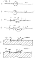
- FIG. 1 The effect of the cutting insert 10 according to the invention can be clearly seen from FIG. 1.
- the expiring chip 18 is guided gently over the flank 123, does not come into contact with sharp-edged steep flanks.
- the vertical or below Longitudinal ribs directed at different angles to the cutting edge has, in the running chip 19 considerable friction overcome that lead to workpiece bonding or deposits 21 lead (Fig. 2). This is because even with one Version in which the longitudinal ribs have different directions to the cutting edge, always have only one longitudinal rib in the direction of chip removal lies, while with all other ribs 22nd Components of motion in the running chip 21 are present lie transversely to the longitudinal direction of the rib in question.
- 3g and h show in particular, the curvatures of the Crest lines 121 each rectified, from the Remove the cutting corner towards the center of the cutting edge.
- the radii of curvature increase from 0.1 to 12 mm near the cutting corner 13 to 2 to 60 mm in the middle of the cutting edge. This applies to turning and milling tools.
- 3 is the corresponding one Radius change from Fig. 3g, which shows the detail E, compared to the representation of Fig. 3h, the detail F shows clearly recognizable. With the changing radii of curvature the angle also decreases from the cutting edge Area to the area away from the cutting corner.
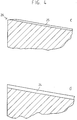
- FIG. 4a shows a cross section approximately vertical to the cutting edge, the flank 122, the apex line 121 and the transition line from edge 122 to adjacent edge 123, the Line 124, are visible.
- the scales 12 are pulled through to the cutting edge and form the chip form inlet.
- the scales 23 in cross section perpendicular to the cutting edge run in an arc and form individual steps or break points.
- the rake face level increases with distance from the Cutting edge lowered compared to this.
- the course of the scales 24 according to Fig. 4d is linearly falling, i.e. below a constant rake angle in relation to the free surface.
- the scales 25 are like this that they run out to the cutting edge 26, i.e. their Height decreases to 0.
- the rake face is perpendicular to Cutting edge 26 initially formed to rise, but falls linearly in areas away from the cutting edge.
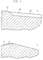
- the cutting insert 4e has a chamfer 27, in the connection of which Scale training 28 is realized.
- the scale lines 281 are slightly below the bevel 27 certain level.
- Fig. 4f shows a cutting insert in which the scales 12 are in the region of a chamfer 31.
- the in Fig. 4f cutting insert shown is in particular made of a high-strength Made of material and extremely hard to machine Workpieces.
- FIGS. 6 to 8 show Inserts for turning.
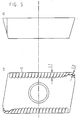
- 5 has an essentially rhombic shape in a plan view, scales extending from the respective cutting corner enclosing an acute angle along the longer cutting edge and having a length L 2 in the cutting corner which is of a greater length L 1 grows and remains approximately constant after about a third of the cutting edge in more distant areas from the effective cutting corner. 5 are designed as described for FIGS. 2 and 3.
- the cutting insert has further scales 29 on the middle one Rake face plateau 30.
- these scales 29 have a much shorter length than that to the cutting edge or a chamfer adjoining there chamfer 12.
- the clearance angle of the cutting plates according to the invention be positive or 0 °, according to FIG. 7a.
- the indexable insert according to FIG. 8 is square and has a clearance angle of 0 °.
- Drilling tools This type is used for drilling in solid metal material and have one stem 32 and more, herein Case two, on the front of the shaft in different Radial distance and offset from each other by 180 ° arranged geometrically similar cutting inserts 33, the Work areas overlap and the radially inner one Indexable insert with one engaged Cutting edge slightly exceeds the drill axis 34.
- a such a drill is for example in DE 40 18 043 A1 described, to which express reference is made.
- the cutting inserts described there with two neighboring ones cutting edges inclined at an obtuse angle to each other can also, as shown in Fig. 9a, c, rectangular or rhombic cutting inserts are used.
- FIGS. 10 and 11 Such cutting inserts are, for example, in FIGS. 10 and 11 shown.
- Fig. 10 shows a square insert in double-edged design, i.e. opposite each other Pages have a scale-like microstructure.
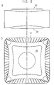
- Fig. 11 shows a corresponding insert in four-edged design, in this embodiment, the Dandruff in the cutting corners 35.
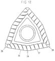
- Fig. 12 shows a trigon-shaped indexable insert in which when drilling two cutting sections 36 and 37 of a cutting edge engaged between adjacent sharp cutting corners 38 stand. The resulting chip sweeps over the one in between blunt cutting corner 39. Take in this embodiment the radii of curvature of the apex lines from the apex Cutting corner 38 from the adjacent pointed cutting corner.
- the invention has Milling tool - shown here as a square insert - On its rake face 10 along the (Main) cutting edge 11 each lying one against the other Scales 12 which have an elongated shape and a longitudinal axis possess that at different angles from the effective Cutting corner 13 towards the cutting edge center and beyond are arranged relative to the cutting edge.
- Scales 12 are on their along the respective flanks as seen from the cutting edge their longitudinal direction curved in an arc, the curvature increasing areas away from the cutting edge or above entire length is constant.
- the cutting insert can be with or be formed without mounting hole 16.
- the milling plate at hand also has at least one additional scale 12a in the area of the face cutting edge 11a with the same direction of curvature as the scales 12b on the main cutting edge.
- the curvature with a radius of curvature R PS of this scale 12a on the cutting edge 11a is at least as large as the radius of curvature of the scales 12b on the main cutting edge near the cutting corner.
- the angle nue PS of the scales 12a, formed by a tangent to the scale outlet in the direction of the cutting edge 11a, is at most as large as the relevant angle of the scales 12b at which they run out relative to the main cutting edge normal 11.
- the face cutting edge 11a begins at the point E PS , where the cutting corner 13, which is defined by a corresponding corner radius, ends and merges into the straight-line cutting edge 11a, which continues to the cutting edge 11 in areas remote from the cutting corner.
- the distance from the point E PS to the point at which the scale 12a ends in the direction of the cutting edge 11a is denoted by c. This distance is between 0.03 mm and 4 mm.
- the scale 12a runs out at a distance d which is in the range of 0.01 mm and 0.5 mm. In the present exemplary embodiment, only one scale 12a is provided, but two or more scales of the same curvature can follow here.
- FIG. 14 shows a section AA according to FIG. 13, which shows that the individual scales 12 (and possibly the scales 12a) immediately adjoin each other.
Landscapes
- Engineering & Computer Science (AREA)
- Mechanical Engineering (AREA)
- Milling Processes (AREA)
- Cutting Tools, Boring Holders, And Turrets (AREA)
- Turning (AREA)
- Auxiliary Devices For Machine Tools (AREA)
- Polishing Bodies And Polishing Tools (AREA)
Description
- Fig. 1
- den Spanablauf bei einem erfindungsgemäßen Schneideinsatz,
- Fig. 2
- den Spanablauf bei einem Schneideinsatz nach dem Stand der Technik bei einer gleichen Schneidoperation wie dem Werkzeug nach Fig. 1,
- Fig. 3
- eine Draufsicht auf ein erfindungsgemäßes Werkzeug,
- Fig. 3a bis 3d
- jeweils Schnittansichten entsprechend A-A, B-B, C-C und D-D nach Fig. 3,
- Fig. 3e und 3f
- vergrößerte Ansichten der Einzelheit A und B nach Fig. 3a und 3b,
- Fig. 3g und 3h
- jeweils vergrößerte Ansichten der Ausschnitte E und F nach Fig. 3,
- Fig. 4a bis 4f
- jeweils Schnitteilansichten senkrecht zur Schneidkante erfindungsgemäßer Werkzeuge,
- Fig. 5
- jeweils eine Seiten- und Draufsicht auf eine Fräswendeschneidplatten nach der vorliegenden Erfindung,
- Fig. 6 bis 8
- erfindungsgemäße Schneidplatten zum Drehen,
- Fig. 9
- eine Ansicht eines mit zwei Schneideinsätzen bestückten Bohrwerkzeuges,
- Fig. 10 bis 12
- jeweils Draufsichten von zum Bohren geeignete Schneideinsätzen,
- Fig. 13
- eine Draufsicht auf ein erfindungsgemäßes Fräswerkzeug und
- Fig. 14
- eine Schnittansicht entsprechend dem Schnitt A - A.
Claims (15)
- Werkzeug für die spanende Bearbeitung von Werkstücken, insbesondere Schneideinsatz, mit einer Vielzahl von nutförmigen und/oder erhabenen Spanformelementen, die entlang der Schneidkante (11) und in einer Reihe nebeneinander angeordnet sind und die eine längliche Erstreckung mit einer hierdurch definierten Längsachse besitzen, wobei die Spanfläche zumindest in Schneidkantennähe eine schuppenförmige Mikrostruktur aufweist und wobei die einzelnen Schuppen (12, 23 bis 25) unmittelbar nebeneinander angrenzend angeordnet sind,
dadurch gekennzeichnet,
daß die Schuppen (12, 23 bis 25) kammartige, gekrümmte Scheitellinien (121) aufweisen, die zur Schneidkante (11) hin mit der Schneidkantennormalen auf der Spanfläche einen Winkel (nue) zwischen 55° und -5° bilden, daß die Schuppen (12, 23 bis 25) jeweils einen Querschnitt parallel zu der Schneidkante aufweisen, der eine steilere Flanke (122) und eine flachere Flanke (123) aufweist, und daß die flachere Flanke (123) jeweils auf der dem Krümmungsmittel punkt zugewandten Seite liegt. - Werkzeug nach Anspruch 1, dadurch gekennzeichnet, daß die Krümmungen der Scheitellinien (121) für Dreh- und Fräs-Schneideinsätze von der Schneidecke (13) weggerichtet sind oder - für Bohrer-Schneideinsätze - die Krümmungen zur Bohrerachse gerichtet sind und/oder daß die Krümmungen von der Schneidecke (13) zur Schneidkantenmitte (14) oder zur nächstliegenden Schneidecke hin zunehmende Radien (für Dreh- oder Fräswerkzeuge) oder abnehmende Radien von Schneidecke zu Schneidecke (für Bohrwerkzeuge) aufweisen, wobei die Krümmung der Scheitellinie (121) jeder einzelnen Schuppe (12) zumindest bei einer wesentlichen Anzahl von Schuppen (12) über ihre Längserstreckung konstant ist, vorzugsweise zwischen 0,1 mm bis 12 mm nahe einer Schneidecke (13) bis auf 2 mm bis 60 mm ansteigend in der Schneidkantenmitte (14) betragen.
- Werkzeug nach einem der Ansprüche 1 oder 2, dadurch gekennzeichnet, daß die maximale Höhe HA, B der Schuppen (12), gemessen als Abstand der Scheitellinie (121) zu dem Fußpunkt (124) einer Flanke (122, 123) zwischen 0,01 mm bis 0,25 mm, vorzugsweise zwischen 0,025 mm und 0,1 mm, liegt und/oder die Höhe der Schuppen (12) mit zunehmendem Abstand von der Schneidkante (13) ansteigt.
- Werkzeug nach einem der Ansprüche 1 bis 3, dadurch gekennzeichnet, daß die Scheitellinien (121) der Schuppen (12) unter einem Spanwinkel von -10° bis +30° verlaufen und/oder mit jeweiligen Schneidkantennormalen von der Schneidecke (13) zur Schneidkantenmitte (14) hin abnehmende Winkel von 55° bis -5°, bilden.
- Werkzeug nach einem der Ansprüche 1 bis 4, dadurch gekennzeichnet, daß die Länge der Schuppen (12) von der Schneidecke (13) zur Schneidkantenmitte (14) oder zur nächsten Schneidecke entlang einer Schneidkante (11) bereichsweise oder stetig zunimmt, wobei vorzugsweise die Länge zwischen 0,15 mm und 8 mm liegt.
- Werkzeug nach einem der Ansprüche 1 bis 5, dadurch gekennzeichnet, daß die Flanken (122, 123) der Schuppen im Querschnitt gerade, ballig oder konkav sind, vorzugsweise unter Krümmungsradien >0,1 mm für steile Flanken und >1,5 mm für flache Flanken und/oder daß die Flanken (122, 123) der Schuppen (12) oder ihre Tangente bezogen auf die Schneidkante (11) auf der den Krümmungsmittelpunkten der Scheitellinien abgewandten Seite unter einem steileren Winkel von 45° ± 30° und auf der gegenüberliegenden Seite unter einem flacheren Winkel <15° verlaufen.
- Werkzeug nach einem der Ansprüche 1 bis 6, dadurch gekennzeichnet, daß die Übergänge der benachbarten Flanken (122, 123) der Schuppen (12) an der Scheitellinie (121) scharfkantig oder abgerundet sind.
- Werkzeug nach einem der Ansprüche 1 bis 7, dadurch gekennzeichnet, daß im Schneideckenbereich eine in Richtung der Winkelhalbierenden verlaufende Schuppe (17) angeordnet ist, deren Scheitel (172) im Querschnitt senkrecht zu der Winkelhalbierenden mindestens die gleiche Höhe wie die Scheitellinien (121) benachbarter Schuppen (12) aufweist und deren Flankenwinkel gleich groß sind, wobei deren Dachwinkel (δ) 130° bis 175°, vorzugsweise 150° bis 170° beträgt und/oder daß der Dachwinkel (δ) der Schuppe (17) mit zunehmendem Abstand von der Schneidecke (13) bereichsweise stetig oder sprunghaft abnimmt.
- Werkzeug nach einem der Ansprüche 1 bis 8, dadurch gekennzeichnet, daß die Schuppen (12, 17, 23 bis 25) sich bis zur Schneidkante erstrecken oder in die Schneidkante (11) auslaufen, wobei die Schuppenhöhe auf 0 mm sinkt oder daß zwischen der Schneidkante (11) und den Schuppen (28) eine Fase (27) oder ein Spanformeinlauf vorgesehen ist oder die Schuppen im Bereich einer Fase ( 31 ) angeordnet sind.
- Werkzeug nach einem der Ansprüche 1 bis 9, dadurch gekennzeichnet, daß auf einem sich über den schneidkantennahen Spanflächenbereich erhabenen Spanflächenplateau weitere Schuppen (19) angeordnet sind, deren Längen vorzugsweise kleiner als die der schneidkantennahen Schuppen (12) sind.
- Werkzeug nach einem der Ansprüche 1 bis 10, dadurch gekennzeichnet, daß die Schuppen im wesentlichen aus abschnittsweisen ebenen Flächen bestehen.
- Werkzeug nach einem der Ansprüche 1 bis 11, dadurch gekennzeichnet, daß nahe einer Schneidecke (13) auch auf der oder angrenzend an die Planschneide (11a) mindestens eine Schuppe (12a) mit gleicher Krümmungsrichtung wie die der Schuppen (12) auf der Hauptschneide (11) angeordnet ist, deren Krümmungen von der Schneidecke (13) weggerichtet sind, wobei vorzugsweise der Krümmungsradius (RPS) der Schuppe(n) (12a) auf der Planschneide (11a) gleich oder größer den Krümmungsradien der Schuppen (12b) ist (sind), die sich nahe der Schneidecke (13) an der Hauptschneide (11) befinden und/oder der Winkel (nuePS) der Schuppe(n) (12a) auf der Planschneide (11a) gleich oder kleiner den Winkeln der Schuppen (12b) ist (sind), die sich nahe der Schneidecke (13) an der Hauptschneide (11) befinden.
- Werkzeug nach Anspruch 12, dadurch gekennzeichnet, daß die schneideckennächste Schuppe (12a) auf der Planschneide (11a) in einem Abstand (c) in der Schneidkantennähe auslaufen, gemessen als Abstand einer ersten Vertikalen, die durch den Schuppenauslauf nahe der Planschneidkante (11a) und senkrecht hierzu verläuft, und einer zweiten Vertikalen, die durch den Berührungspunkt (EPS) der Planschneide (11a) und der Schneidecke (13) senkrecht zur Planschneidkante verläuft, wobei der Abstand (c) im Bereich des minimalen Zahnvorschubes (fzmin) und des Produktes von maximaler Zähnezahl und des maximalen Zahnvorschubes (zmax . fzmax) liegt, vorzugsweise zwischen 0,03 mm ≤ c ≤ 4 mm.
- Werkzeug nach einem der Ansprüche 12 oder 13, dadurch gekennzeichnet, daß die Schuppe(n) (12a) auf der Planschneide (11a) in einem Abstand (d) zur Planschneidkante (11a) ausläuft (auslaufen), der das ein- bis vierfache des Planlauffehlers beträgt, vorzugsweise im Bereich 0,01 mm ≤ d ≤ 0,5 mm liegt.
- Bohrwerkzeug für Bohrungen in Metallvollmaterial, mit einem Schaft (32) und mehreren an der Stirnseite des Schaftes (32) in verschiedenem Radialabstand und um gleiche Umfangswinkel gegeneinander versetzt zueinander angeordnete, geometrisch ähnliche Wendeschneidplatten (33), deren Arbeitsbereiche sich überdecken, wobei die radial innere Wendeschneidplatte mit ihrer einen in Eingriff stehenden Schneidkante die Bohrerachse (34) geringfügig überschreitet, dadurch gekennzeichnet, daß die radial innere Wendeschneidplatte mit einer Vielzahl von nutförmigen und/oder erhabenen Spanformelementen, die entlang der Schneidkante (11) und in einer Reihe nebeneinander angeordnet sind und die eine längliche Erstreckung mit einer hierdurch definierten Längsachse besitzen, wobei die Spanfläche zumindest in Schneidkantennähe eine schuppenförmige Mikrostruktur aufweist und wobei die einzelnen Schuppen (12, 23 bis 25) unmittelbar nebeneinander angrenzend angeordnet sind und kammartige, gekrümmte Scheitellinien (121) aufweisen, die zur Schneidkante (11) hin mit der Schneidkantennormalen auf der Spanfläche einen Winkel (nue) zwischen 55° und -5° bilden, wobei die Schuppen jeweils einen Querschnitt parallel zu der Schneidkante (11) aufweisen, der eine steilere Flanke (122) und eine flachere Flanke (123) aufweist und die flachere Flanke (123) jeweils auf der dem Krümmungsmittelpunkt zugewandten Seite liegt.
Applications Claiming Priority (5)
| Application Number | Priority Date | Filing Date | Title |
|---|---|---|---|
| DE4415491A DE4415491A1 (de) | 1994-05-02 | 1994-05-02 | Werkzeug für die spanende Bearbeitung |
| DE4415491 | 1994-05-02 | ||
| DE4431796A DE4431796A1 (de) | 1994-05-02 | 1994-09-07 | Fräswerkzeug |
| DE4431796 | 1994-09-07 | ||
| PCT/DE1995/000515 WO1995029782A1 (de) | 1994-05-02 | 1995-04-12 | Werkzeug für die spanende bearbeitung |
Publications (2)
| Publication Number | Publication Date |
|---|---|
| EP0758279A1 EP0758279A1 (de) | 1997-02-19 |
| EP0758279B1 true EP0758279B1 (de) | 1998-08-26 |
Family
ID=25936218
Family Applications (1)
| Application Number | Title | Priority Date | Filing Date |
|---|---|---|---|
| EP95915784A Expired - Lifetime EP0758279B1 (de) | 1994-05-02 | 1995-04-12 | Werkzeug für die spanende bearbeitung |
Country Status (6)
| Country | Link |
|---|---|
| US (1) | US5810520A (de) |
| EP (1) | EP0758279B1 (de) |
| JP (1) | JPH09512753A (de) |
| AT (1) | ATE170117T1 (de) |
| DE (3) | DE4431796A1 (de) |
| WO (1) | WO1995029782A1 (de) |
Cited By (1)
| Publication number | Priority date | Publication date | Assignee | Title |
|---|---|---|---|---|
| DE19937707A1 (de) * | 1999-08-10 | 2001-03-01 | Baerlocher Gmbh | Werkzeug-Oberflächen mit definierter Mikrostruktur zur Abweisung von Ablagerungen |
Families Citing this family (31)
| Publication number | Priority date | Publication date | Assignee | Title |
|---|---|---|---|---|
| KR100379345B1 (ko) * | 1994-12-10 | 2003-06-09 | 켄나메탈 헤르텔 아게 베르크조위게 플러스 하르트쉬토페 | 고체금속드릴링용드릴링공구 |
| DE19822948B4 (de) * | 1997-05-26 | 2006-06-22 | Heisel, Uwe, Prof. Dr.-Ing. Dr.h.c. | Spanabhebendes, drehendes Werkzeug |
| DE19724319C1 (de) * | 1997-06-10 | 1998-10-08 | Fette Wilhelm Gmbh | Verfahren zur Beeinflussung des Spanflußverhaltens von Werkzeugflächen |
| DE19731246B4 (de) * | 1997-07-21 | 2007-07-05 | Widia Gmbh | Bohr- oder Fräswerkzeug und Verfahren zur Ermittlung der absoluten Freiwinkel der Freiflächenbereiche eines Schneideinsatzes |
| US6217264B1 (en) * | 1998-05-30 | 2001-04-17 | Korloy, Inc. | Cutting insert having an improved chip breaker |
| US6050752A (en) * | 1999-03-19 | 2000-04-18 | Kennametal Inc. | Cutting insert |
| DE19920192A1 (de) * | 1999-05-03 | 2000-11-16 | Kennametal Inc | Schneideinsatz, insbesondere Wendeplatte |
| US6267541B1 (en) * | 1999-07-09 | 2001-07-31 | Kennametal Pc Inc. | Indexable insert with a V-shaped chip breaker |
| EP1252955A1 (de) * | 2001-04-26 | 2002-10-30 | Mitsubishi Materials Corporation | Indexierbarer Schneideinsatz |
| JP3696805B2 (ja) * | 2001-06-14 | 2005-09-21 | スター精密株式会社 | 工作機械の移動位置設定方法 |
| US20040213638A1 (en) * | 2003-04-24 | 2004-10-28 | Waggle Nicholas F. | Cutting insert with thermal crack barrier |
| USD487759S1 (en) | 2003-05-28 | 2004-03-23 | Kennametal Inc. | Cutting insert |
| USD491588S1 (en) | 2003-05-28 | 2004-06-15 | Kennametal Inc. | Cutting insert |
| USD487758S1 (en) | 2003-05-28 | 2004-03-23 | Kennametal Inc. | Cutting insert |
| USD487757S1 (en) | 2003-05-28 | 2004-03-23 | Kennametal Inc. | Cutting insert |
| USD487755S1 (en) | 2003-05-28 | 2004-03-23 | Kennametal Inc. | Cutting insert |
| USD488176S1 (en) | 2003-05-28 | 2004-04-06 | Kennametal Inc. | Cutting insert |
| AT500865B1 (de) * | 2004-07-22 | 2009-01-15 | Boehlerit Gmbh & Co Kg | Schneidplatte mit strukturierten flächen |
| DE102005007676B3 (de) * | 2005-02-19 | 2006-07-13 | Mws Schneidwerkzeuge Gmbh & Co. Kg | Anordnung und Befestigung von Schneidplatten |
| SE528813C2 (sv) * | 2005-03-16 | 2007-02-20 | Sandvik Intellectual Property | Planfrässkär med klack i anslutning till bieggen |
| US7278805B2 (en) | 2005-10-03 | 2007-10-09 | Kennametal Inc. | Cutting insert for effective chip control |
| US7634897B2 (en) * | 2005-11-16 | 2009-12-22 | Les Equipments Prenbec Inc. | Rotary cutting machine with replaceable cutting teeth |
| WO2007056857A1 (en) * | 2005-11-16 | 2007-05-24 | Les Équipments Prenbec Inc. | Reversible saw tooth |
| US8905685B2 (en) * | 2006-09-13 | 2014-12-09 | Mitsubishi Materials Corporation | Roughing insert and roughing end mill |
| EP2060353B1 (de) | 2006-09-13 | 2012-12-19 | Mitsubishi Materials Corporation | Aufraueinsatz und aufrauschaftfräser |
| JP5023628B2 (ja) * | 2006-09-13 | 2012-09-12 | 三菱マテリアル株式会社 | ラフィングエンドミル |
| JP5515504B2 (ja) * | 2008-08-22 | 2014-06-11 | 三菱マテリアル株式会社 | 切削インサート |
| US9168599B2 (en) | 2011-11-17 | 2015-10-27 | Les Equipements Prenbec Inc. | Saw disk with improved chip discharge |
| US9144845B1 (en) * | 2012-03-01 | 2015-09-29 | The Boeing Company | Cutting tools with textured surfaces |
| KR20150135185A (ko) * | 2013-03-29 | 2015-12-02 | 스미또모 덴꼬오 하드메탈 가부시끼가이샤 | cBN 절삭 공구의 제조 방법 및 cBN 절삭 공구 |
| EP3034214A1 (de) * | 2014-12-19 | 2016-06-22 | Pramet Tools, S.R.O. | Bohrer und Bohreinsatz mit Spanbrechervorsprüngen |
Family Cites Families (12)
| Publication number | Priority date | Publication date | Assignee | Title |
|---|---|---|---|---|
| DE3105377A1 (de) * | 1981-02-14 | 1982-10-28 | Karl Gustav Dipl.-Ing. 8500 Nürnberg Hertel jun. | Schneideinsatz fuer schneidwerkzeuge |
| EP0088505B1 (de) * | 1982-02-26 | 1988-06-01 | Carboloy Inc. | Bohrer und Wegwerfschneidplatten dafür |
| US4588332A (en) * | 1982-11-03 | 1986-05-13 | General Electric Company | Self-sharpening tool constructions having chip-grooves |
| US4859122A (en) * | 1987-08-17 | 1989-08-22 | Gte Valenite Corporation | Polygonal cutting insert |
| IL84078A (en) * | 1987-10-02 | 1990-09-17 | Iscar Ltd | Cutting insert |
| SU1611583A1 (ru) * | 1988-10-25 | 1990-12-07 | Ленинградский Филиал Специального Производственно-Технологического Бюро "Оргпримтвердосплав" | Многогранна режуща пластина |
| SE469215B (sv) * | 1989-06-22 | 1993-06-07 | Seco Tools Ab | Skaer vars spaanformande yta aer foersedd med urtagningar vinklade mot skaereggen. |
| US5116167A (en) * | 1991-02-19 | 1992-05-26 | Kennametal Inc. | Cutting insert with chip control |
| DE4118070C2 (de) * | 1991-06-01 | 1995-02-09 | Widia Heinlein Gmbh | Werkzeug für die spanende Bearbeitung |
| DE4141368A1 (de) * | 1991-12-14 | 1993-06-17 | Krupp Widia Gmbh | Schneideinsatz |
| DE4239235A1 (de) * | 1992-11-21 | 1994-05-26 | Krupp Widia Gmbh | Schneideinsatz |
| IL109054A (en) * | 1994-03-21 | 1998-07-15 | Iscar Ltd | Cutting insert |
-
1994
- 1994-09-07 DE DE4431796A patent/DE4431796A1/de not_active Withdrawn
-
1995
- 1995-04-12 JP JP7527931A patent/JPH09512753A/ja not_active Ceased
- 1995-04-12 DE DE59503349T patent/DE59503349D1/de not_active Expired - Lifetime
- 1995-04-12 DE DE19580420T patent/DE19580420D2/de not_active Expired - Fee Related
- 1995-04-12 US US08/737,202 patent/US5810520A/en not_active Expired - Lifetime
- 1995-04-12 AT AT95915784T patent/ATE170117T1/de not_active IP Right Cessation
- 1995-04-12 WO PCT/DE1995/000515 patent/WO1995029782A1/de not_active Ceased
- 1995-04-12 EP EP95915784A patent/EP0758279B1/de not_active Expired - Lifetime
Cited By (2)
| Publication number | Priority date | Publication date | Assignee | Title |
|---|---|---|---|---|
| DE19937707A1 (de) * | 1999-08-10 | 2001-03-01 | Baerlocher Gmbh | Werkzeug-Oberflächen mit definierter Mikrostruktur zur Abweisung von Ablagerungen |
| DE19937707C2 (de) * | 1999-08-10 | 2003-03-27 | Baerlocher Gmbh | Werkzeug-Oberflächen mit definierter Mikrostruktur zur Abweisung von Ablagerungen |
Also Published As
| Publication number | Publication date |
|---|---|
| WO1995029782A1 (de) | 1995-11-09 |
| JPH09512753A (ja) | 1997-12-22 |
| US5810520A (en) | 1998-09-22 |
| EP0758279A1 (de) | 1997-02-19 |
| DE4431796A1 (de) | 1996-03-14 |
| ATE170117T1 (de) | 1998-09-15 |
| DE19580420D2 (de) | 1997-02-27 |
| DE59503349D1 (de) | 1998-10-01 |
Similar Documents
| Publication | Publication Date | Title |
|---|---|---|
| WO1995029782A1 (de) | Werkzeug für die spanende bearbeitung | |
| EP0796162B1 (de) | Bohrwerkzeug für bohrungen in metallvollmaterial | |
| DE4118065C2 (de) | Vieleckiger oder runder Schneideinsatz | |
| EP0980297B1 (de) | Schneideinsatz für die spanabhebende bearbeitung | |
| DE68907004T2 (de) | Schneideinsatz. | |
| EP0674559B1 (de) | Schneideinsatz | |
| EP0792201B1 (de) | Schneidplatte zur spanabhebenden bearbeitung von werkstücken | |
| EP1670608B1 (de) | Schneideinsatz | |
| EP0674558B1 (de) | Schneideinsatz | |
| EP0787049B1 (de) | Vieleckiger schneideinsatz | |
| EP2060356B1 (de) | Sägeblatt mit einem Grundkörper und Zähnen mit Schneiden | |
| EP0073926B1 (de) | Schneidwerkzeug, insbesondere Wendeschneidplatte | |
| DE4239236A1 (de) | Schneideinsatz | |
| EP1855827B1 (de) | Wendeschneidplatte | |
| DE10021879A1 (de) | Vollbohrer für Werkzeugmaschinen | |
| DE10235606A1 (de) | Vollbohrer für Werkzeugmaschinen | |
| EP0696942B1 (de) | Vieleckiger schneideinsatz | |
| EP1181123A1 (de) | Schneideinsatz, insbesondere wendeplatte | |
| EP1009573B1 (de) | Gewindeschneidplatte | |
| EP0706432B1 (de) | Schneideinsatz | |
| EP3898045A1 (de) | Schneidwerkzeug | |
| WO1994027768A1 (de) | Schneideinsatz | |
| EP0842003B1 (de) | Stecheinsatz | |
| DE19725341B4 (de) | Schneidwerkzeug für schälartige Zerspanungsbearbeitungen | |
| DE4415491A1 (de) | Werkzeug für die spanende Bearbeitung |
Legal Events
| Date | Code | Title | Description |
|---|---|---|---|
| PUAI | Public reference made under article 153(3) epc to a published international application that has entered the european phase |
Free format text: ORIGINAL CODE: 0009012 |
|
| 17P | Request for examination filed |
Effective date: 19961011 |
|
| AK | Designated contracting states |
Kind code of ref document: A1 Designated state(s): AT BE CH DE DK ES FR GB IT LI LU NL PT SE |
|
| GRAG | Despatch of communication of intention to grant |
Free format text: ORIGINAL CODE: EPIDOS AGRA |
|
| 17Q | First examination report despatched |
Effective date: 19971114 |
|
| GRAG | Despatch of communication of intention to grant |
Free format text: ORIGINAL CODE: EPIDOS AGRA |
|
| GRAH | Despatch of communication of intention to grant a patent |
Free format text: ORIGINAL CODE: EPIDOS IGRA |
|
| GRAG | Despatch of communication of intention to grant |
Free format text: ORIGINAL CODE: EPIDOS AGRA |
|
| GRAH | Despatch of communication of intention to grant a patent |
Free format text: ORIGINAL CODE: EPIDOS IGRA |
|
| GRAH | Despatch of communication of intention to grant a patent |
Free format text: ORIGINAL CODE: EPIDOS IGRA |
|
| GRAA | (expected) grant |
Free format text: ORIGINAL CODE: 0009210 |
|
| AK | Designated contracting states |
Kind code of ref document: B1 Designated state(s): AT BE CH DE DK ES FR GB IT LI LU NL PT SE |
|
| PG25 | Lapsed in a contracting state [announced via postgrant information from national office to epo] |
Ref country code: NL Free format text: LAPSE BECAUSE OF FAILURE TO SUBMIT A TRANSLATION OF THE DESCRIPTION OR TO PAY THE FEE WITHIN THE PRESCRIBED TIME-LIMIT Effective date: 19980826 Ref country code: ES Free format text: THE PATENT HAS BEEN ANNULLED BY A DECISION OF A NATIONAL AUTHORITY Effective date: 19980826 |
|
| REF | Corresponds to: |
Ref document number: 170117 Country of ref document: AT Date of ref document: 19980915 Kind code of ref document: T |
|
| REG | Reference to a national code |
Ref country code: CH Ref legal event code: EP |
|
| GBT | Gb: translation of ep patent filed (gb section 77(6)(a)/1977) |
Effective date: 19980827 |
|
| REF | Corresponds to: |
Ref document number: 59503349 Country of ref document: DE Date of ref document: 19981001 |
|
| ET | Fr: translation filed | ||
| PG25 | Lapsed in a contracting state [announced via postgrant information from national office to epo] |
Ref country code: SE Free format text: LAPSE BECAUSE OF FAILURE TO SUBMIT A TRANSLATION OF THE DESCRIPTION OR TO PAY THE FEE WITHIN THE PRESCRIBED TIME-LIMIT Effective date: 19981126 Ref country code: PT Free format text: LAPSE BECAUSE OF FAILURE TO SUBMIT A TRANSLATION OF THE DESCRIPTION OR TO PAY THE FEE WITHIN THE PRESCRIBED TIME-LIMIT Effective date: 19981126 Ref country code: DK Free format text: LAPSE BECAUSE OF FAILURE TO SUBMIT A TRANSLATION OF THE DESCRIPTION OR TO PAY THE FEE WITHIN THE PRESCRIBED TIME-LIMIT Effective date: 19981126 |
|
| NLV1 | Nl: lapsed or annulled due to failure to fulfill the requirements of art. 29p and 29m of the patents act | ||
| PG25 | Lapsed in a contracting state [announced via postgrant information from national office to epo] |
Ref country code: LU Free format text: LAPSE BECAUSE OF NON-PAYMENT OF DUE FEES Effective date: 19990412 Ref country code: AT Free format text: LAPSE BECAUSE OF NON-PAYMENT OF DUE FEES Effective date: 19990412 |
|
| PG25 | Lapsed in a contracting state [announced via postgrant information from national office to epo] |
Ref country code: LI Free format text: LAPSE BECAUSE OF NON-PAYMENT OF DUE FEES Effective date: 19990430 Ref country code: CH Free format text: LAPSE BECAUSE OF NON-PAYMENT OF DUE FEES Effective date: 19990430 Ref country code: BE Free format text: LAPSE BECAUSE OF NON-PAYMENT OF DUE FEES Effective date: 19990430 |
|
| PLBE | No opposition filed within time limit |
Free format text: ORIGINAL CODE: 0009261 |
|
| STAA | Information on the status of an ep patent application or granted ep patent |
Free format text: STATUS: NO OPPOSITION FILED WITHIN TIME LIMIT |
|
| 26N | No opposition filed | ||
| BERE | Be: lapsed |
Owner name: WIDIA G.M.B.H. Effective date: 19990430 |
|
| REG | Reference to a national code |
Ref country code: CH Ref legal event code: PL |
|
| REG | Reference to a national code |
Ref country code: GB Ref legal event code: IF02 |
|
| PGFP | Annual fee paid to national office [announced via postgrant information from national office to epo] |
Ref country code: GB Payment date: 20050404 Year of fee payment: 11 |
|
| PGFP | Annual fee paid to national office [announced via postgrant information from national office to epo] |
Ref country code: FR Payment date: 20050412 Year of fee payment: 11 |
|
| PG25 | Lapsed in a contracting state [announced via postgrant information from national office to epo] |
Ref country code: GB Free format text: LAPSE BECAUSE OF NON-PAYMENT OF DUE FEES Effective date: 20060412 |
|
| PGFP | Annual fee paid to national office [announced via postgrant information from national office to epo] |
Ref country code: IT Payment date: 20060430 Year of fee payment: 12 |
|
| GBPC | Gb: european patent ceased through non-payment of renewal fee |
Effective date: 20060412 |
|
| REG | Reference to a national code |
Ref country code: FR Ref legal event code: ST Effective date: 20061230 |
|
| PG25 | Lapsed in a contracting state [announced via postgrant information from national office to epo] |
Ref country code: FR Free format text: LAPSE BECAUSE OF NON-PAYMENT OF DUE FEES Effective date: 20060502 |
|
| PG25 | Lapsed in a contracting state [announced via postgrant information from national office to epo] |
Ref country code: IT Free format text: LAPSE BECAUSE OF NON-PAYMENT OF DUE FEES Effective date: 20070412 |
|
| PGFP | Annual fee paid to national office [announced via postgrant information from national office to epo] |
Ref country code: DE Payment date: 20140917 Year of fee payment: 20 |
|
| REG | Reference to a national code |
Ref country code: DE Ref legal event code: R071 Ref document number: 59503349 Country of ref document: DE |