EP0758206B1 - Sicherungselement für ein steckbares gerüst oder regal - Google Patents
Sicherungselement für ein steckbares gerüst oder regal Download PDFInfo
- Publication number
- EP0758206B1 EP0758206B1 EP95915973A EP95915973A EP0758206B1 EP 0758206 B1 EP0758206 B1 EP 0758206B1 EP 95915973 A EP95915973 A EP 95915973A EP 95915973 A EP95915973 A EP 95915973A EP 0758206 B1 EP0758206 B1 EP 0758206B1
- Authority
- EP
- European Patent Office
- Prior art keywords
- securing element
- accordance
- section
- indicator cap
- shaft section
- Prior art date
- Legal status (The legal status is an assumption and is not a legal conclusion. Google has not performed a legal analysis and makes no representation as to the accuracy of the status listed.)
- Expired - Lifetime
Links
- 239000004033 plastic Substances 0.000 claims description 5
- 239000000463 material Substances 0.000 claims description 4
- 229910052751 metal Inorganic materials 0.000 claims description 4
- 239000002184 metal Substances 0.000 claims description 4
- 239000002023 wood Substances 0.000 claims description 4
- 230000002093 peripheral effect Effects 0.000 claims description 3
- 239000000919 ceramic Substances 0.000 claims 2
- 239000011521 glass Substances 0.000 claims 2
- 230000006978 adaptation Effects 0.000 claims 1
- 238000006073 displacement reaction Methods 0.000 abstract 1
- 229910000831 Steel Inorganic materials 0.000 description 4
- 239000010959 steel Substances 0.000 description 4
- 229910052782 aluminium Inorganic materials 0.000 description 3
- XAGFODPZIPBFFR-UHFFFAOYSA-N aluminium Chemical compound [Al] XAGFODPZIPBFFR-UHFFFAOYSA-N 0.000 description 3
- 229910000639 Spring steel Inorganic materials 0.000 description 2
- 230000005484 gravity Effects 0.000 description 2
- 240000000731 Fagus sylvatica Species 0.000 description 1
- 235000010099 Fagus sylvatica Nutrition 0.000 description 1
- 230000009286 beneficial effect Effects 0.000 description 1
- 238000010276 construction Methods 0.000 description 1
- 238000000034 method Methods 0.000 description 1
- 238000010008 shearing Methods 0.000 description 1
Images



Classifications
-
- A—HUMAN NECESSITIES
- A47—FURNITURE; DOMESTIC ARTICLES OR APPLIANCES; COFFEE MILLS; SPICE MILLS; SUCTION CLEANERS IN GENERAL
- A47B—TABLES; DESKS; OFFICE FURNITURE; CABINETS; DRAWERS; GENERAL DETAILS OF FURNITURE
- A47B57/00—Cabinets, racks or shelf units, characterised by features for adjusting shelves or partitions
- A47B57/30—Cabinets, racks or shelf units, characterised by features for adjusting shelves or partitions with means for adjusting the height of detachable shelf supports
- A47B57/40—Cabinets, racks or shelf units, characterised by features for adjusting shelves or partitions with means for adjusting the height of detachable shelf supports consisting of hooks coacting with openings
- A47B57/408—Cabinets, racks or shelf units, characterised by features for adjusting shelves or partitions with means for adjusting the height of detachable shelf supports consisting of hooks coacting with openings with a security device
-
- A—HUMAN NECESSITIES
- A47—FURNITURE; DOMESTIC ARTICLES OR APPLIANCES; COFFEE MILLS; SPICE MILLS; SUCTION CLEANERS IN GENERAL
- A47B—TABLES; DESKS; OFFICE FURNITURE; CABINETS; DRAWERS; GENERAL DETAILS OF FURNITURE
- A47B57/00—Cabinets, racks or shelf units, characterised by features for adjusting shelves or partitions
- A47B57/30—Cabinets, racks or shelf units, characterised by features for adjusting shelves or partitions with means for adjusting the height of detachable shelf supports
- A47B57/40—Cabinets, racks or shelf units, characterised by features for adjusting shelves or partitions with means for adjusting the height of detachable shelf supports consisting of hooks coacting with openings
Definitions
- the invention relates to a securing element for Secured by a hook tab and a support established connection for attaching a crossbar on the support of a pluggable scaffold or Shelves, especially pallet shelves, the Securing element from a locking spring as well a locking pin with a headboard and one Shaft part exists.
- Pallet racks consist of a framework frame with several, two in a plane at a distance arranged from each other and parallel to each other Crossbeams as pallet supports.
- Material is mostly steel or aluminum.
- the crossbars are attached to two each other opposite, vertical supports the truss frame by means of a hook tab attached to each of the two ends of the crossbeams, the hook tabs at the ends of the Crossbars are welded on.
- the supports of the Half-timbered frame have in height arranged at regular intervals Openings (perforations in the wall of the supports) on.
- the hook tabs can be elbows, from which in height at regular intervals one above the other and overall one above the other e.g.
- Such a locking element is a locking pin, essentially one consisting of head and shaft Nail resembles, with the shaft at a distance is bent downwards at right angles from the head.
- This securing element is used after rack assembly in an additional step with the shaft opposite openings in the hook tab and pushed in the support and reaches behind then the wall with its bent shaft part the prop, causing the hook tab to move against the support is to be prevented.
- a securing element is also known (available at of the brand DEXION SPEEDLOCK IV) consisting of a Leaf spring made of spring steel and of a one-piece Locking pin made of aluminum, consisting of a headboard and consists of a bolt-shaped shaft part, the latter is not angled.
- the leaf spring For attachment to the hook tab the leaf spring has a hook in the upper area that when applying the leaf spring to the hook tab in one Engages opening of the hook tab and engages behind it.
- the leaf spring has a perforation in the lower area, through which the locking pin first through an opening the hook tab and then through an opening in the support is pushed.
- the locking pin is then on the outside his head on the leaf spring and penetrates with his Shafts the holes in the leaf spring and the openings in the hook tab and in the support so that the shaft Shifts between the hook plate and the support in the counteracts vertical and being the locking pin by means of the leaf spring against the hook tab and thus also is pressed against and into the support.
- the object of the invention is a Creating a securing element that adopts a condition which indicates that an applied force has a predetermined Value has exceeded.
- the head part and shaft part of the Securing pin releasably connected, and the The head part and shaft part are connected by a Detachable tilting movement of the shaft part around a bearing point, when an applied force is larger than a predetermined one Is worth.
- the head part preferably includes an indicator cap that has an axial bore starting from the cap base, wherein the bore has a first part that fits is made to at least one end of the shaft part record, and another lying against the cap bottom Part, the other part of a contact surface on the Has locking spring, and the other part larger Has dimensions than that of the first part.
- the bore is advantageously a central bore. she can but also one outside the central axis of the Indicator cap lying, eccentric hole.
- the bearing point around which the shaft portion of the locking pin the tilting movement is preferably in the central Area of perforation in the locking spring through which the shaft part penetrates the locking spring. At least part of the contact surface of the indicator cap on the Safety spring expediently forms a Counter bearing point.
- the contact surface of the locking spring is advantageously in the form of an annular disk.
- the outer peripheral surface of the indicator cap is useful circular in cross-section; she but can also be essentially triangular in cross section, quadrangular or polygonal or oval, preferably be elliptical.
- the shaft part of the locking pin is preferred a cylindrical shear pin with its one end area in a positive and non-positive manner the axial cylindrical bore of the indicator cap can be pressed in.
- the shear pin can also be used in Cross section essentially triangular, four or polygonal or oval, preferably elliptical, be trained.
- the indicator cap expediently consists of a material with a strength that is sufficient on the one hand the positive and non-positive connection of indicator cap and shear pin and on the other hand enough resistance on Counter bearing point for levering off the shear pin from the axial cylindrical bore of the indicator cap to apply.
- the indicator cap can therefore made of plastic, metal, preferably aluminum, or made of wood, preferably beech wood.
- the indicator cap in a contrasting color is advantageous colored to the color of the locking spring.
- the shear pin is preferably a bolt or a tubular steel sleeve, where steel is a material is of the desired hardness and training as Pipe sleeve affects the shearing process favorably.
- the invention can be advantageous on a pluggable Shelf, especially pallet rack, applied is, however, on such an application not limited but can also be used by others pluggable scaffolding, e.g. B. in the construction sector, application Find.
- Fig. 1 is the locking spring, which is a well-known leaf spring made of spring steel. This has a perforation in the lower area, through which the locking pin according to the drawing of pushed left to right in the horizontal and is held positively.
- the locking pin consists of a as a tubular sleeve Metal, preferably steel, formed shaft part, the shear pin 2, and preferably one head part made of plastic, the indicator cap 3, the indicator cap 3 on the outside the locking spring 1 rests and the shear pin 2 on the one hand through the aforementioned perforation in the locking spring 1 in a central axial cylindrical bore 4 in the indicator cap 3 up to their cap bottom 5 in this form and is non-positively pressed and on the other hand thence through the aforementioned hole in the locking spring 1 long in the horizontal is that it bears against the locking spring 1 Hook tab penetrates and into the on the hook tab adjacent support penetrates (see Fig.
- the indicator cap 3 has on the cap base 5, the central axial cylindrical Bore 4 for receiving the shear pin 2; this widens at a short distance from the cap base 5 conical to an annular disc Contact surface 6 of the indicator cap 3 on the locking spring 1; this conical extension is with the reference numeral 7 denotes.
- the safety spring 1 has a drawing in the upper area Hook 8, which when the safety spring 1 engages in the hook tab and engages behind it, and two more, above the hook 8 in a plane spaced apart Hooks 9 protrude against the edge of a cut-out the hook tab, so that the attachment the locking spring 1 made on the hook tab is (see Fig. 2a).
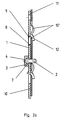
- Fig. 2a shows the connection securing element-hook tab-support in properly secured condition, especially without the special hook tab and support Vertical loads against each other are exposed.
- 1 is again the one described for FIG. 1 Designated spring. This lies on the hook tab 10, which in turn with her Back rests on the support 11.
- the lower Hook 8 of the locking spring 1 extends through and engages behind the hook tab 10 while the top Hook 9 of the locking spring 1 against the edge 12 a punched out in the hook tab 10 and support the locking spring 1 there.
- connection Indicator cap 3 shown with shear pin 2, wherein the shear pin 2 horizontally by corresponding Openings (punched out) in the hook tab 10 and hook bracket 10 and bracket 11 through the bracket 11 to the through the three or four walls of the support 11 protrudes in this formed cavity.
- 10 ' are the hooks of the hook tab 10, the through openings (punched out) in the support 11 reach behind the wall, whereby the (detachable) Connection between hook tab 10 and support 11 is made.
- Fig. 2b shows the connection securing element-hook tab-support in the loaded state of e.g. F - 7000 - 9000 N after e.g. the fork of one Forklift accidentally accidentally cuts a crossbar Pallet rack has raised something from below, so that the hook tab 10 with the locking spring 1st and the support 11 as a result of the in opposite Directional forces according to the two arrows F slightly shifted against each other in the vertical are.
- Fig. 2b shows that here the shear pin 2 something from the support - around one certain angle - from the horizontal towards is tilted to the vertical, namely around the Pivotal and bearing point P1 of the shear pin 2 in the central Perforation area in the locking spring 1.
- the counter bearing point P2 of the indicator cap 3 and Shear pin 2 existing locking pin is located between the front of the locking spring 1 and the outer edge of the annular disk-shaped contact surface 6 of the indicator cap 3.
- P2 is the counter bearing point to storage point P1; against him the indicator cap 3 pressed and held when the shear pin 2 during its tilting movement from the central axial cylindrical Lever out hole 4.
- the one before (Fig. 2a) horizontally in the central axial cylindrical Bore 4 of the indicator cap 3 is positive and non-positive seated shear pin 2 begins with its tilting movement to pry out of the hole 4, whereby its tilting movement from the horizontal through the conical extension 7 of the bore 4 of the indicator cap 3 is favored.
- FIG. 3 shows in an enlarged view for better illustration The detail in detail is shown in X in Fig. 2b, and there are the same parts in Fig. 3 with same reference numerals as in Fig. 2b, 3 to the description of FIG. 2b is referred.
- Fig. 4 shows the known locking spring 1 with the indicator cap 3, as one Forklift operator or a control person or - offers in view. Is the indicator cap 3 dropped from the locking spring 1 Visibly indicated that the connection of the securing element to the hook-link bracket is damaged and secured again must become.
- the preferably made of plastic Indicator cap 3 can be in a contrasting color to the color of the Retaining spring 1 can be colored so that it falls off the locking spring 1 is optically easy to register.
- Fig. 5 shows the indicator cap 3 in cross section and three Views (side, top and bottom), with equal parts with the same reference numerals as in Fig. 1-4.
Landscapes
- Snaps, Bayonet Connections, Set Pins, And Snap Rings (AREA)
- Dowels (AREA)
- Forklifts And Lifting Vehicles (AREA)
- Insertion Pins And Rivets (AREA)
- Pivots And Pivotal Connections (AREA)
Description
- Fig. 1
- im Querschnitt die Sicherungsfeder mit dem erfindungsgemäßen Sicherungselement,
- Fig. 2
- in leicht verkleinertem Maßstab im Querschnitt
die Verbindung Sicherungselement-Hakenlasche-Stütze,
und zwar
- in Fig. 2a in ordnungsgemäß gesichertem Zustand und
- in Fig. 2b in einem Zustand, in dem sich Hakenlasche und Stütze in der Vertikalen gegeneinander verschoben haben,
- Fig. 3
- einen Detail-Ausschnitt aus Fig. 2b in vergrößerter Darstellung sowie
- Fig. 4
- zur Veranschaulichung die bekannte Sicherungsfeder mit einer erfindungsgemäßen Indikatorkappe in Ansicht aus der Sicht eines Gabelstaplerführers oder einer Kontrollperson oder -stelle.
Claims (17)
- Sicherungselement zur Sicherung der durch eine Lasche (10) und eine Stütze (11) hergestellten Verbindung zur Anbringung eines Querbalkens an der Stütze eines steckbares Regals oder Gerüsts, wobei das Sicherungselement eine Sicherungsfeder (1), die an der Lasche (10) anliegt, welche Lasche (10) an der Stütze (11) anliegt, sowie einen durch die Sicherungsfeder (1) durchdringenden Sicherungsstift mit einem Kopfteil (3) und einem Schaftteil (2) aufweist,
dadurch gekennzeichnet,
daß Kopfteil (3) und Schaftteil 82) lösbar miteinander verbunden sind, und daß die Verbindung von Kopfteil (3) und Schaftteil (2) durch eine Kippbewegung des Schaftteils (2) um einen im Bereich einer Lochung in der Sicherungsfeder (1) liegenden Lagerpunkt (P1) lösbar ist, wenn eine auf das Sicherungselement (1) aufgebrachte Kraft größer als ein vorbestimmter Wert ist. - Sicherungselement nach Anspruch 1, dadurch gekennzeichnet, daß der Kopfteil eine Indikatorkappe (3) umfaßt, die ausgehend vom Kappenboden eine axiale Bohrung aufweist, wobei die Bohrung einen ersten Teil (4) aufweist, der passend gemacht ist, um zumindest ein Ende des Schaftteils (2) aufzunehmen, und einen weiteren dem Kappenboden anliegenden Teil (7) , wobei der weitere Teil eine Anlagefläche an der Sicherungsfeder aufweist, und der weitere Teil größere Abmessungen als die des ersten Teils aufweist.
- Sicherungselement nach Anspruch 2, dadurch gekennzeichnet, daß die axiale Bohrung (4) eine zylindrische mittige Bohrung ist.
- Sicherungselement nach Anspruch 2, dadurch gekennzeichnet, daß die axiale Bohrung (4) eine exzentrische Bohrung ist.
- Sicherungselement nach einem der Ansprüche 2 bis 4, dadurch gekennzeichnet, daß der weitere Teil (7) ausgehend vom ersten Teil (4) der Bohrung erweitert ist.
- Sicherungselement nach einem der Ansprüche 2 bis 5, dadurch gekennzeichnet, daß die Indikatorkappe (3) mit wenigstens einem Teil ihrer der Sicherungsfeder (1) zugewandten Fläche eine als Gegenlagerpunkt (P2) ausreichende Anlagefläche (6) bildet.
- Sicherungselement nach einem der Ansprüche 2 bis 6, dadurch gekennzeichnet, daß die der Sicherungsfeder (1) zugewandte Anlagefläche (6) der Indikatorkappe (3) ringscheibenförmig ist.
- Sicherungselement nach einem der Ansprüche 2 bis 7, dadurch gekennzeichnet, daß die Kontakt- oder Außenumfangsfläche der Indikatorkappe (3) im Querschnitt kreisscheibenförmig oder kreislinienförmig ist.
- Sicherungselement nach einem der Ansprüche 1 bis 8, dadurch gekennzeichnet, daß der Schaftteil (2) eine formschlüßige Fassung in der axialen Bohrung (4) der Indikatorkappe (3) ist.
- Sicherungselement nach einem der Ansprüche 1 bis 9, dadurch gekennzeichnet, daß die Außenumfangsfläche der Indikatorkappe (3) im Querschnitt im wesentlichen dreieckig, vier- oder mehreckig oder oval oder elliptisch ausgebildet ist.
- Sicherungselement nach einem der Ansprüche 1 bis 10, dadurch gekennzeichnet, daß das Schaftteil (2) im Querschnitt im wesentlichen dreieckig, vier- oder mehreckig oder oval oder elliptisch ausgebildet ist.
- Sicherungselement nach einem der Ansprüche 1 bis 11, dadurch gekennzeichnet, daß die Indikatorkappe (3) aus einem Werkstoff von einer Festigkeit besteht, die ausreicht, die Verbindung von Indikatorkappe (3) und Schaftteil (2) herzustellen und genügend Widerstandskraft am Gegenlagerpunkt (P2) zum Aushebeln des Schaftteils (2) aus der axialen Bohrung (4) der Indikatorkappe aufzubringen.
- Sicherungselement nach einem der Ansprüche 1 bis 12, dadurch gekennzeichnet, daß die Indikatorkappe (3) aus Kunststoff, Metall, Glas, Keramik oder Holz besteht.
- Sicherungselement nach einem der Ansprüche 1 bis 13, dadurch gekennzeichnet, daß die Indikatorkappe (3) in einer Kontrastfarbe zur Farbe der Sicherungsfeder (1) eingefärbt ist.
- Sicherungselement nach einem der Ansprüche 1 bis 14, dadurch gekennzeichnet, daß der Schaftteil (2) ein Bolzen oder eine Rohrhülse ist.
- Sicherungselement nach einem der Ansprüche 1 bis 15, dadurch gekennzeichnet, daß der Schaftteil (2) aus Metall, Kunststoff, Glas, Keramik oder Holz besteht.
- Sicherungselement nach einem der Ansprüche 1 bis 16, dadurch gekennzeichnet, daß der Lagerpunkt (P1) des Schaftteils (2) im zentralen Bereich einer Lochung in der Sicherungsfeder (1) liegt, durch welche der Schaftteil (2) die Sicherungsfeder durchdringt.
Applications Claiming Priority (3)
| Application Number | Priority Date | Filing Date | Title |
|---|---|---|---|
| DE4415988 | 1994-05-06 | ||
| DE4415988A DE4415988C2 (de) | 1994-05-06 | 1994-05-06 | Sicherungselement für ein steckbares Regal oder Gerüst |
| PCT/IB1995/000322 WO1995030358A1 (de) | 1994-05-06 | 1995-05-04 | Sicherungselement für ein steckbares gerüst oder regal |
Publications (2)
| Publication Number | Publication Date |
|---|---|
| EP0758206A1 EP0758206A1 (de) | 1997-02-19 |
| EP0758206B1 true EP0758206B1 (de) | 1999-03-24 |
Family
ID=6517445
Family Applications (1)
| Application Number | Title | Priority Date | Filing Date |
|---|---|---|---|
| EP95915973A Expired - Lifetime EP0758206B1 (de) | 1994-05-06 | 1995-05-04 | Sicherungselement für ein steckbares gerüst oder regal |
Country Status (4)
| Country | Link |
|---|---|
| EP (1) | EP0758206B1 (de) |
| AT (1) | ATE177918T1 (de) |
| DE (2) | DE4415988C2 (de) |
| WO (1) | WO1995030358A1 (de) |
Families Citing this family (3)
| Publication number | Priority date | Publication date | Assignee | Title |
|---|---|---|---|---|
| GB2324709B (en) | 1997-05-02 | 2001-12-05 | Dexion Group Plc | Beam end connector |
| DE202012008595U1 (de) * | 2012-09-07 | 2013-12-09 | Tegometall International Ag | Aushebesicherung für eine Regaltraverse |
| DE202016001259U1 (de) | 2016-02-26 | 2016-04-07 | Matthias Messerschmid | Sicherungelement für Baugerüste |
Family Cites Families (5)
| Publication number | Priority date | Publication date | Assignee | Title |
|---|---|---|---|---|
| GB1438627A (en) * | 1972-03-10 | 1976-06-09 | Birmingham Pallet Co Ltd | Racking |
| DE2553330A1 (de) * | 1975-11-25 | 1977-05-26 | Interlake Inc | Konstruktionsglied und -anordnung |
| US4244476A (en) * | 1979-06-27 | 1981-01-13 | Acrow (Automation) Limited | Racking |
| FR2603783B1 (fr) * | 1986-09-15 | 1990-09-21 | Alser | Piece d'assemblage d'une lisse d'un casier sur un montant |
| GB2257024B (en) * | 1991-06-19 | 1995-05-10 | Barrett Storage Systems Plc | Lock |
-
1994
- 1994-05-06 DE DE4415988A patent/DE4415988C2/de not_active Expired - Fee Related
-
1995
- 1995-05-04 WO PCT/IB1995/000322 patent/WO1995030358A1/de not_active Ceased
- 1995-05-04 AT AT95915973T patent/ATE177918T1/de not_active IP Right Cessation
- 1995-05-04 DE DE59505444T patent/DE59505444D1/de not_active Expired - Fee Related
- 1995-05-04 EP EP95915973A patent/EP0758206B1/de not_active Expired - Lifetime
Also Published As
| Publication number | Publication date |
|---|---|
| DE59505444D1 (de) | 1999-04-29 |
| EP0758206A1 (de) | 1997-02-19 |
| DE4415988C2 (de) | 1997-03-13 |
| WO1995030358A1 (de) | 1995-11-16 |
| ATE177918T1 (de) | 1999-04-15 |
| DE4415988A1 (de) | 1995-11-09 |
Similar Documents
| Publication | Publication Date | Title |
|---|---|---|
| EP0753457B1 (de) | Riegelelement | |
| DE102008015066A1 (de) | Belageinheit mit Abhebesicherung und Verfahren zur Sicherung einer Belageinheit gegen Abheben sowie Verfahren zur Entsicherung einer gegen Abheben gesicherten Belageinheit | |
| DE2357773A1 (de) | Verriegelungsvorrichtung | |
| DE3147081A1 (de) | "geruest fuer betonschalungen" | |
| DE202015103519U1 (de) | Aufhängevorrichtung für ein Möbel | |
| DE202020005145U1 (de) | Kragarmregal | |
| WO2009155890A2 (de) | Baugerüst mit aushebesicherungsvorrichtung für belageinheiten | |
| DE4415988C2 (de) | Sicherungselement für ein steckbares Regal oder Gerüst | |
| DE102016205836A1 (de) | Haken zum Versetzen von Schalungselementen | |
| EP0965289A2 (de) | Zerlegbares Regal | |
| DE3515260A1 (de) | Kragarmregal fuer schwere lasten | |
| DE10115811A1 (de) | Kragarmregal | |
| DE4421690A1 (de) | Variables Warenpräsentations- und Aufnahmesystem | |
| EP0736648B1 (de) | Gerüst | |
| EP0519316A1 (de) | Kragarmregal | |
| DE9407530U1 (de) | Sicherungselement für ein steckbares Gerüst oder Regal | |
| EP3748107B1 (de) | Montageadapter, sicherheitsgeländer, bausatz für ein baugerüst sowie baugerüst und verfahren hierfür | |
| EP0432372B1 (de) | Kragarm-Regal | |
| EP2993112B2 (de) | Rungensystem für einen Nutzfahrzeug- oder Anhängerdachaufbau | |
| CH668756A5 (de) | Stapelstaendervorrichtung. | |
| DE202022101496U1 (de) | Regal | |
| EP0409051A2 (de) | Gerüst | |
| DE10260134B4 (de) | Rollensatz zum Versetzen eines Lagerregals | |
| DE3126092A1 (de) | "regalpalette" | |
| DE4406732C2 (de) | Gerüst, insbesondere für das Bauwesen |
Legal Events
| Date | Code | Title | Description |
|---|---|---|---|
| PUAI | Public reference made under article 153(3) epc to a published international application that has entered the european phase |
Free format text: ORIGINAL CODE: 0009012 |
|
| 17P | Request for examination filed |
Effective date: 19961206 |
|
| AK | Designated contracting states |
Kind code of ref document: A1 Designated state(s): AT BE CH DE DK FR GB IT LI NL |
|
| GRAG | Despatch of communication of intention to grant |
Free format text: ORIGINAL CODE: EPIDOS AGRA |
|
| 17Q | First examination report despatched |
Effective date: 19980129 |
|
| GRAG | Despatch of communication of intention to grant |
Free format text: ORIGINAL CODE: EPIDOS AGRA |
|
| GRAH | Despatch of communication of intention to grant a patent |
Free format text: ORIGINAL CODE: EPIDOS IGRA |
|
| GRAH | Despatch of communication of intention to grant a patent |
Free format text: ORIGINAL CODE: EPIDOS IGRA |
|
| GRAA | (expected) grant |
Free format text: ORIGINAL CODE: 0009210 |
|
| AK | Designated contracting states |
Kind code of ref document: B1 Designated state(s): AT BE CH DE DK FR GB IT LI NL |
|
| PG25 | Lapsed in a contracting state [announced via postgrant information from national office to epo] |
Ref country code: NL Free format text: LAPSE BECAUSE OF FAILURE TO SUBMIT A TRANSLATION OF THE DESCRIPTION OR TO PAY THE FEE WITHIN THE PRESCRIBED TIME-LIMIT Effective date: 19990324 Ref country code: IT Free format text: LAPSE BECAUSE OF FAILURE TO SUBMIT A TRANSLATION OF THE DESCRIPTION OR TO PAY THE FEE WITHIN THE PRESCRIBED TIME-LIMIT;WARNING: LAPSES OF ITALIAN PATENTS WITH EFFECTIVE DATE BEFORE 2007 MAY HAVE OCCURRED AT ANY TIME BEFORE 2007. THE CORRECT EFFECTIVE DATE MAY BE DIFFERENT FROM THE ONE RECORDED. Effective date: 19990324 Ref country code: GB Free format text: LAPSE BECAUSE OF NON-PAYMENT OF DUE FEES Effective date: 19990324 Ref country code: FR Free format text: LAPSE BECAUSE OF FAILURE TO SUBMIT A TRANSLATION OF THE DESCRIPTION OR TO PAY THE FEE WITHIN THE PRESCRIBED TIME-LIMIT Effective date: 19990324 |
|
| REF | Corresponds to: |
Ref document number: 177918 Country of ref document: AT Date of ref document: 19990415 Kind code of ref document: T |
|
| REG | Reference to a national code |
Ref country code: CH Ref legal event code: EP |
|
| REF | Corresponds to: |
Ref document number: 59505444 Country of ref document: DE Date of ref document: 19990429 |
|
| PG25 | Lapsed in a contracting state [announced via postgrant information from national office to epo] |
Ref country code: AT Free format text: LAPSE BECAUSE OF NON-PAYMENT OF DUE FEES Effective date: 19990504 |
|
| PG25 | Lapsed in a contracting state [announced via postgrant information from national office to epo] |
Ref country code: LI Free format text: LAPSE BECAUSE OF NON-PAYMENT OF DUE FEES Effective date: 19990531 Ref country code: CH Free format text: LAPSE BECAUSE OF NON-PAYMENT OF DUE FEES Effective date: 19990531 Ref country code: BE Free format text: LAPSE BECAUSE OF NON-PAYMENT OF DUE FEES Effective date: 19990531 |
|
| PG25 | Lapsed in a contracting state [announced via postgrant information from national office to epo] |
Ref country code: DK Free format text: LAPSE BECAUSE OF FAILURE TO SUBMIT A TRANSLATION OF THE DESCRIPTION OR TO PAY THE FEE WITHIN THE PRESCRIBED TIME-LIMIT Effective date: 19990624 |
|
| PGFP | Annual fee paid to national office [announced via postgrant information from national office to epo] |
Ref country code: DE Payment date: 19990628 Year of fee payment: 5 |
|
| EN | Fr: translation not filed | ||
| NLV1 | Nl: lapsed or annulled due to failure to fulfill the requirements of art. 29p and 29m of the patents act | ||
| GBV | Gb: ep patent (uk) treated as always having been void in accordance with gb section 77(7)/1977 [no translation filed] |
Effective date: 19990324 |
|
| BERE | Be: lapsed |
Owner name: DEXION HOLDING G.M.B.H. Effective date: 19990531 |
|
| REG | Reference to a national code |
Ref country code: CH Ref legal event code: PL |
|
| PLBE | No opposition filed within time limit |
Free format text: ORIGINAL CODE: 0009261 |
|
| STAA | Information on the status of an ep patent application or granted ep patent |
Free format text: STATUS: NO OPPOSITION FILED WITHIN TIME LIMIT |
|
| 26N | No opposition filed | ||
| PG25 | Lapsed in a contracting state [announced via postgrant information from national office to epo] |
Ref country code: DE Free format text: LAPSE BECAUSE OF NON-PAYMENT OF DUE FEES Effective date: 20010301 |