EP0757952B1 - Vorderer Umwerfer für ein Fahrrad - Google Patents
Vorderer Umwerfer für ein Fahrrad Download PDFInfo
- Publication number
- EP0757952B1 EP0757952B1 EP96305786A EP96305786A EP0757952B1 EP 0757952 B1 EP0757952 B1 EP 0757952B1 EP 96305786 A EP96305786 A EP 96305786A EP 96305786 A EP96305786 A EP 96305786A EP 0757952 B1 EP0757952 B1 EP 0757952B1
- Authority
- EP
- European Patent Office
- Prior art keywords
- derailleur
- bracket
- bushing
- cage plate
- frame
- Prior art date
- Legal status (The legal status is an assumption and is not a legal conclusion. Google has not performed a legal analysis and makes no representation as to the accuracy of the status listed.)
- Expired - Lifetime
Links
- 230000007246 mechanism Effects 0.000 claims description 11
- 230000008878 coupling Effects 0.000 claims 1
- 238000010168 coupling process Methods 0.000 claims 1
- 238000005859 coupling reaction Methods 0.000 claims 1
- 238000002372 labelling Methods 0.000 description 2
- 230000002093 peripheral effect Effects 0.000 description 2
- 238000004873 anchoring Methods 0.000 description 1
- 238000010276 construction Methods 0.000 description 1
- 230000000116 mitigating effect Effects 0.000 description 1
- 230000004048 modification Effects 0.000 description 1
- 238000012986 modification Methods 0.000 description 1
- 230000000717 retained effect Effects 0.000 description 1
Images


Classifications
-
- B—PERFORMING OPERATIONS; TRANSPORTING
- B62—LAND VEHICLES FOR TRAVELLING OTHERWISE THAN ON RAILS
- B62M—RIDER PROPULSION OF WHEELED VEHICLES OR SLEDGES; POWERED PROPULSION OF SLEDGES OR SINGLE-TRACK CYCLES; TRANSMISSIONS SPECIALLY ADAPTED FOR SUCH VEHICLES
- B62M9/00—Transmissions characterised by use of an endless chain, belt, or the like
- B62M9/04—Transmissions characterised by use of an endless chain, belt, or the like of changeable ratio
- B62M9/06—Transmissions characterised by use of an endless chain, belt, or the like of changeable ratio using a single chain, belt, or the like
- B62M9/10—Transmissions characterised by use of an endless chain, belt, or the like of changeable ratio using a single chain, belt, or the like involving different-sized wheels, e.g. rear sprocket chain wheels selectively engaged by the chain, belt, or the like
- B62M9/12—Transmissions characterised by use of an endless chain, belt, or the like of changeable ratio using a single chain, belt, or the like involving different-sized wheels, e.g. rear sprocket chain wheels selectively engaged by the chain, belt, or the like the chain, belt, or the like being laterally shiftable, e.g. using a rear derailleur
- B62M9/131—Front derailleurs
- B62M9/135—Mounting the derailleur on the frame
-
- B—PERFORMING OPERATIONS; TRANSPORTING
- B62—LAND VEHICLES FOR TRAVELLING OTHERWISE THAN ON RAILS
- B62M—RIDER PROPULSION OF WHEELED VEHICLES OR SLEDGES; POWERED PROPULSION OF SLEDGES OR SINGLE-TRACK CYCLES; TRANSMISSIONS SPECIALLY ADAPTED FOR SUCH VEHICLES
- B62M9/00—Transmissions characterised by use of an endless chain, belt, or the like
- B62M9/04—Transmissions characterised by use of an endless chain, belt, or the like of changeable ratio
- B62M9/06—Transmissions characterised by use of an endless chain, belt, or the like of changeable ratio using a single chain, belt, or the like
- B62M9/10—Transmissions characterised by use of an endless chain, belt, or the like of changeable ratio using a single chain, belt, or the like involving different-sized wheels, e.g. rear sprocket chain wheels selectively engaged by the chain, belt, or the like
- B62M9/12—Transmissions characterised by use of an endless chain, belt, or the like of changeable ratio using a single chain, belt, or the like involving different-sized wheels, e.g. rear sprocket chain wheels selectively engaged by the chain, belt, or the like the chain, belt, or the like being laterally shiftable, e.g. using a rear derailleur
- B62M9/131—Front derailleurs
- B62M9/134—Mechanisms for shifting laterally
- B62M9/1344—Mechanisms for shifting laterally limiting or positioning the movement
Definitions
- the present invention is directed to bicycle derailleurs and, more specifically, to a bicycle front derailleur with an adjusting mechanism for adjusting the position of a cage plate relative to a plurality of chainwheels.
- Document DE-A-31 18 035 shows a front derailleur according to the preamble of claim 1.
- Sports bicycles are usually equipped with front and rear derailleur gear-shift mechanisms.
- the front derailleur is a mechanism for selecting between double and triple front chainrings on which the chain lies.
- the chainrings are selected at discretion based on the rider's needs, and the position of the front derailleur cage plate is usually adjusted to correspond to the largest selected chainring.
- a clamp-band unit fastens the cage plate to the seat-tube and the cage plate is placed into the optimum position by adjusting the position of the clamp-band unit on the bicycle during assembly.
- Some front derailleur are mounted to the bicycle using a non-adjustable bracket that is fixed to the bottom bracket assembly.
- multiple bracket configurations must be constructed to position the front derailleur properly for the different large chainwheels that the cyclist may choose.
- an increase in front derailleur bracket types leads to an increase in unit cost for the part.
- the multiple bracket types also complicates management tasks such as storage and delivery.
- the present invention is directed to a front derailleur bracket which incorporates an adjustment mechanism for adjusting a chain cage radially with respect to the chainwheels. As a result, fewer front derailleur brackets may accommodate more chainring configurations.
- a bicycle front derailleur includes a frame bracket for fixing the derailleur to a bicycle frame, a cage plate for guiding a chain among a plurality of chainwheels, and a radial adjustment mechanism for adjusting a position of the cage plate substantially radially relative to the chainwheels.
- a derailleur bracket fixes the cage plate to the frame bracket, wherein the derailleur bracket defines a derailleur bracket opening.
- a bushing is disposed in the derailleur bracket opening. The bushing defines a bushing opening such that the bushing has an eccentric shape relative to the bushing opening.
- a fastener extends through the bushing opening for fastening the bushing to the frame bracket. Rotation of the bushing varies the position of the derailleur bracket and hence the position of the cage plate relative to the chainwheels.
- the derailleur bracket opening and the bushing each may have an oval shape, wherein the derailleur bracket opening has a longitudinal axis which extends radially outwardly from a centerline of the plurality of chainwheels.
- the position of the cage plate may be adjusted radially with respect to the chainwheels while maintaining the horizontal attitude of the cage plate.
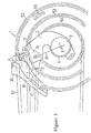
- FIG. 1 is a side view of a particular embodiment of a front derailleur 1 according to the present invention.
- a seat-tube bracket 2 is fixed to a bicycle frame bottom bracket (not illustrated) in order to install the front derailleur 1 to the bicycle.
- the seat-tube bracket 2 is fixed coaxially, specifically by means of a nut (not illustrated), to the bicycle frame bottom bracket assembly.
- the center line of the crank axle which extends from the bottom bracket assembly is indicated by L.
- the seat-tube bracket 2 is provided with a through hole 3 which aligns with a corresponding opening in the bottom bracket.
- the seat-tube bracket 2 comprises an axle member 4 and a radial extension member 5 that extends substantially radially as an integral piece with the axle member 4.
- a front derailleur bracket 6 is fastened to the outer end member of the radial extension member 5.
- the major-axis direction of the oval hole 7 is a substantially radial direction R relative to a chainring described below.
- a bushing 8 is used that fits neatly into the oval hole 7.
- Bushing 8 can be attached to and detached from the oval hole 7. If both of the oval holes 7 share the same shape, then the bushing 8 can be used for both of the oval holes, lending to convenience.
- Bolt-threading hole 9 is off-center along the major-axis direction of the bushing 8 so that bushing 8 is eccentric relative to bolt-threading hole 9.
- Screw holes 11 are formed in the seat-tube bracket 2, and a bolt 12 is screwed into the screw hole 11 via the bolt-threading hole 9 of the bushing 8 fitted into the oval hole 7.
- the front derailleur bracket 6 is equipped with a link-supporting unit 13, in an integral or assembled manner.
- the link-supporting unit 13 comprises a base component 14 and side-walls 15, which are vertically bent shoulder segments of the base component 14.
- a first pivot 16, lying parallel to base component 14, is retained by a side-wall 15, and a coil spring 17 has been fitted to the first pivot 16.
- One end of the coil spring 17 connects to side-wall 15, and a flange 18 is fixed to the other end of the first pivot 16.
- a first link 19 is provided between the flange 18 and the end surface of the coil spring 17.
- the first link 19 comprises a ring member 21 at its end; a planar member 22, which is integrally formed to the ring 21 and extends parallel to the first pivot 16 to the side-wall 15; and a second pivot retainer member 23 which is an integrally bent end section of the planar member 22.
- a second pivot 24 is provided between the second pivot retainer member 23 and a second link 25.
- An extension member 35 is provided to the second link 25 as a unified extension continuous with the second link 25.
- One end of a third pivot 26 is attached to the second link 25, and the other end of third pivot 26 rotatably supports one end of a third link 27.
- One end of a fourth pivot 28 is attached to the side-wall 15 parallel to the third pivot 26, and the other end of the third link 27 is fixed to this end of fourth pivot 28.
- the other end of the fourth pivot 28 is rotatably supported by the side-wall 15 protruding upward at one end of the base component 14.
- the four links (side-wall 15, first link 19, second link 25, third link 27) and the four pivots (first pivot 16, second pivot 24, third pivot 26, fourth pivot 28) comprise a four-link mechanism roughly shaped as a parallelogram.
- a cage plate 36 is integrally provided to the extension member 35.
- the cage plate 36 is substantially a rectangular box, and its top and bottom sides are open.
- the cage plate 36 comprises a left plate 37, a right plate 38, a front plate 39 and a rear plate 41.
- the front plate 39 and the rear plate 41 are substantially parallel.
- a seat-tube support 42 is fixed to the link-supporting unit 13, and the seat-tube support 42 is provided with a semicircular ring member 44 that fits onto the seat tube component of the frame bottom bracket.
- the front derailleur 1 although supported by means of the seat-tube bracket 2 fixed to the frame bottom bracket, is also supported by the seat tube (not illustrated) of the frame by means of the semicircular ring member 44.
- a cable anchor member for anchoring one end of a wire is provided to the first link 19.
- a chain 51 passes through the space enclosed by the left plate 37, the right plate 38, the front plate 39, and the rear plate 41.
- the chain 51 selectively engages with a large diameter chainring 52, a middle diameter chainring 53, or a small diameter chainring 54.
- the cage plate 36 In order to have a suitably positioned area of the cage plate 36 contact the chain 51, the cage plate 36 must be properly positioned with respect to the largest chainwheel. However, depending on the type of bicycle and the needs of the rider, the largest chainring varies in its number of teeth, which determines the proportional diameter of the chainring. Thus, when replacing the illustrated largest-diameter chainring 52 with a chainring 55 having a smaller radius, or when installing the smaller chainring 55 from the outset, the cage plate 36 must be radially positioned closer towards the center line L. To accomplish this, the bolt 12 is loosened and removed from the seat-tube bracket 2, and the bushing 8 is removed from the front derailleur bracket 6. The removed bushing 8 is reversed 180° and fitted back into the oval hole 7.
- the bolt 12 is screwed into the hole 11, and the front derailleur bracket 6 is again fixed to the seat-tube bracket 2.
- the radial position of the bolt 12 does not change, the radial position of the front derailleur bracket 6 does change as a result of the eccentric shape of bushing 8 relative to hole 9.
- This radial differential in radial positions is given as distance 2a, where distance "a" is the distance between the center of the oval hole 7 and the center of the bolt-threading hole 9.
- Figure 1 shows a contact area A (the region inside the dotted circle) on the cage plate 36 that comes into contact with the chain 51 when shifting to and from the largest-diameter chainring 52. As shown, contact area A is substantially aligned to the peripheral line of chainring 52. The absolute position of contact area A on the cage plate 36 does not move and the contact area A is a substantially unchanging region.
- a contact area B related to the chainring 53 is similarly maintained as a substantially unchanging region, and a contact area C related to the chainring 54 is also maintained as a substantially unchanging region.
- the contact areas A, B, and C move substantially radially due to the movement of the front derailleur bracket 6 in the major-axis direction of the oval hole 7.
- the direction of the oval hole 7 is the direction in which the cage plate moves as it follows the outer periphery of the chainring 52 in a substantially radial direction.
- the direction from the center point of the axis center line L to the contact area B which is the intermediate area between the contact areas A and C, could be aligned with the major-axis direction of the oval hole 7. In most cases, however, it is not necessary to adhere strictly to this relationship between the major-axis direction and the radial direction due to the mitigating effects of flexible chains on various types of resistance during gear changes.
- the distance 2a in the embodiment described above can be set to accommodate a one-tooth increase (or decrease) in the radial size of the largest diameter chainwheel 52.
- the distance 2a in the embodiment described above can be set to accommodate a two or more tooth increase (or decrease) in the radial size of the largest diameter chainwheel 52.
- the hole 9 in bushing 8 need not be located exactly as shown in Figure 2.
- the eccentric distance of the bolt-threading hole 9 of the bushing 8 can be small to produce a smaller distance differential, if desired. If a bushing having a single bolt-threading hole is employed, then the cage plate 36 can be moved radially on a discrete basis.
Landscapes
- Engineering & Computer Science (AREA)
- Chemical & Material Sciences (AREA)
- Combustion & Propulsion (AREA)
- Transportation (AREA)
- Mechanical Engineering (AREA)
- Transmissions By Endless Flexible Members (AREA)
- Devices For Conveying Motion By Means Of Endless Flexible Members (AREA)
- Gears, Cams (AREA)
- Escalators And Moving Walkways (AREA)
Claims (13)
- Ein Kettenblattumwerfer für ein Fahrrad mit einem Rahmen, der einen unteren Träger aufweist, um eine Kurbelachse unterzubringen, wobei der untere Träger eine zur Kurbelachse koaxiale Öffnung aufweist, wobei die Kettenschaltung aus folgendem besteht:einem Rahmenträger (2) zur Befestigung der Kettenschaltung am Fahrradrahmen;einer Gehäuseplatte (36) zum Führen einer Kette (51) innerhalb einer Vielzahl von Kettenblättern (52, 53, 54);einem Kettenschaltungsträger (6) zur Befestigung der Gehäuseplatte (36) am Rahmenträger (2); undeinem Radialeinstellungsmittel (7, 8, 11, 12) zur Einstellung einer Position der Gehäuseplatte (36) im wesentlichen radial bezüglich der Kettenblätter (52, 53, 54), wobei das Radialeinstellungsmittel (7, 8, 11, 12) die Position des Kettenschaltungsträgers (6) bezüglich des Rahmenträgers (2) einstellt; dadurch gekennzeichnet, daß:der Rahmenträger (2) eine Öffnung (3) aufweist, die mit der entsprechenden Öffnung im unteren Träger des Fahrradrahmens ausgerichtet ist, wenn der Rahmenträger (2) am Fahrradrahmen befestigt ist, wobei der Rahmenträger (2) am unteren Träger des Fahrradrahmens befestigt ist, so daß die Öffnungen koaxial sind; und daß:das Radialeinstellungsmittel eine Buchse (8) umfaßt, durch die der Kettenschaltungsträger (6) mit dem Rahmenträger (2) verbunden ist, wobei die Buchse (8) bezüglich des Rahmenträgers (2) zur Einstellung der Position der Gehäuseplatte (36) bewegt werden kann, wobei die Buchse (8) eine exzentrisch angeordnete Öffnung (9) zur Einstellung der Position der Gehäuseplatte auf einer diskreten Basis aufweist.
- Kettenschaltung gemäß Anspruch 1, wobei das Radialeinstellungsmittel (7, 8, 11, 12) eine Winkelposition der Gehäuseplatte (36) bezüglich einer senkrechten Ebene des Fahrrads hält, während die Position der Gehäuseplatte (36) eingestellt wird, wodurch die Drehung der Gehäuseplatte um eine senkrechte Achse des Fahrrads verhindert wird.
- Kettenschaltung gemäß Anspruch 1 oder Anspruch 2, weiterhin bestehend aus einem viergliedrigen Verbindungsmechanismus (15, 16, 19, 24, 26, 27, 28), der die Gehäuseplatte (36) an den Kettenschaltungsträger (6) kuppelt.
- Kettenschaltung gemäß einem der vorhergehenden Ansprüche, wobei das Radialeinstellungsmittel (7, 8, 11, 12) einen Einstellungsbereich der Position der Gehäuseplatte (36) aufweist, der einer Zunahme der radialen Größe des Kettenblatts (52) mit der höchsten Anzahl von Zähnen aus einer Vielzahl von Kettenblättern (52, 53, 54) von einem Zahn ungefähr gleicht.
- Kettenschaltung gemäß einem der Ansprüche 1 bis 3, wobei das Radialeinstellungsmittel (7, 8, 11, 12) einen Einstellungsbereich der Position der Gehäuseplatte (36) aufweist, der einer Zunahme der radialen Größe des Kettenblatts (52) mit der höchsten Anzahl von Zähnen aus einer Vielzahl von Kettenblättern (52, 53, 54) von zwei oder mehr Zähnen ungefähr gleicht.
- Kettenschaltung gemäß einem der vorhergehenden Ansprüche, wobei die Kettenschaltung weiterhin ein Tragmittel (42, 44) beinhaltet, das geformt ist, um auf das Sitzrohr des Fahrrads zu passen.
- Kettenschaltung gemäß einem der vorhergehenden Ansprüche, wobei die Buchse (8) zu einer Vielzahl von diskreten Positionen bewegt werden kann, wobei die Position der Gehäuseplatte durch diskrete Inkremente eingestellt werden kann.
- Kettenschaltung gemäß Anspruch 7, wobei die Buchse (8) zu zwei Positionen bewegt werden kann.
- Kettenschaltung gemäß einem der vorhergehenden Ansprüche, wobei die Buchse (8) in einer eiförmigen Öffnung (7) angeordnet ist, die im Kettenschaltungsträger (6) mit einer Längsachse (R) gebildet wird, welche sich von einer Mittellinie (L) der Vielzahl von Kettenblättern (52, 53, 54) radial nach außen erstreckt, wenn die Kettenschaltung am Rahmen befestigt ist.
- Kettenschaltung gemäß Anspruch 9, wobei die Buchse (8) eine exzentrisch angeordnete Öffnung (9) bildet, so daß die Buchse (8) bezüglich der exzentrischen Öffnung (9) eine exzentrische Form aufweist.
- Kettenschaltung gemäß Anspruch 1, wobei der Kettenschaltungsträger (6) eine Kettenschaltungsträgeröffnung (7) bildet und wobei die Buchse (8) in der Kettenschaltungsträgeröffnung (7) angebracht ist und die exzentrisch angeordnete Öffnung (9) bildet, so daß die Buchse (8) bezüglich der exzentrisch angeordneten Öffnung (9) eine exzentrische Form aufweist; und weiterhin ein Befestigungselement beinhaltet, das durch die exzentrisch angeordnete Öffnung (9) zur Befestigung der Buchse (8) am Rahmenträger (2) verläuft.
- Kettenschaltung gemäß Anspruch 11, wobei die Kettenschaltungsträgeröffnung (7) und die Buchse (8) beide eiförmig sind.
- Kettenschaltung gemäß Anspruch 11 oder 12, wobei die Kettenschaltungsträgeröffnung (7) eine Längsachse (R) aufweist, die sich von einer Mittellinie (L) der Vielzahl von Kettenblättern (52, 53, 54) radial nach außen erstreckt, wenn die Kettenschaltung am Rahmen befestigt ist.
Applications Claiming Priority (3)
| Application Number | Priority Date | Filing Date | Title |
|---|---|---|---|
| JP22111495A JP3328113B2 (ja) | 1995-08-07 | 1995-08-07 | 自転車のフロントディレーラ |
| JP221114/95 | 1995-08-07 | ||
| JP22111495 | 1995-08-07 |
Publications (2)
| Publication Number | Publication Date |
|---|---|
| EP0757952A1 EP0757952A1 (de) | 1997-02-12 |
| EP0757952B1 true EP0757952B1 (de) | 2000-03-15 |
Family
ID=16761706
Family Applications (1)
| Application Number | Title | Priority Date | Filing Date |
|---|---|---|---|
| EP96305786A Expired - Lifetime EP0757952B1 (de) | 1995-08-07 | 1996-08-06 | Vorderer Umwerfer für ein Fahrrad |
Country Status (6)
| Country | Link |
|---|---|
| US (1) | US5846148A (de) |
| EP (1) | EP0757952B1 (de) |
| JP (1) | JP3328113B2 (de) |
| CN (1) | CN1069275C (de) |
| DE (1) | DE69607083T2 (de) |
| TW (1) | TW305811B (de) |
Cited By (1)
| Publication number | Priority date | Publication date | Assignee | Title |
|---|---|---|---|---|
| CN1861476B (zh) * | 2005-05-14 | 2010-05-12 | Sram德国有限公司 | 自行车架上的具有可变安装装置的前变速器 |
Families Citing this family (35)
| Publication number | Priority date | Publication date | Assignee | Title |
|---|---|---|---|---|
| DE19706156A1 (de) * | 1997-02-17 | 1998-08-20 | Sram De Gmbh | Kettenumlegeeinrichtung für Fahrräder |
| US6117032A (en) * | 1998-02-13 | 2000-09-12 | Shimano, Inc. | Protective plate for bicycle chain |
| US6277044B1 (en) * | 1998-05-20 | 2001-08-21 | Shimano, Inc. | Front derailleur with protective plate and connecting band |
| US7025698B2 (en) * | 2000-01-20 | 2006-04-11 | Christopher Alan Wickliffe | Front derailleur with annular chain guide, bicycle and method of operation |
| US6454671B1 (en) | 2000-01-20 | 2002-09-24 | Christopher Alan Wickliffe | Front bicycle derailleur with annular chain guide |
| US6612950B2 (en) * | 2001-10-31 | 2003-09-02 | Shimano Inc. | Front derailleur mounting arrangement |
| US7066856B1 (en) | 2002-09-06 | 2006-06-27 | Rogers James K | Chain ring protector |
| JP2005186764A (ja) * | 2003-12-25 | 2005-07-14 | Shimano Inc | 自転車用フロントディレイラ |
| US7331890B2 (en) * | 2004-02-26 | 2008-02-19 | Shimano Inc. | Motorized front derailleur mounting member |
| EP1571076A1 (de) * | 2004-03-05 | 2005-09-07 | Campagnolo S.R.L. | Befestigungsvorrichtung für Fahrradsgangschaltung und Fahrradgangschaltung mit solcher Befestigungsvorrichtung |
| US20060068955A1 (en) * | 2004-09-28 | 2006-03-30 | Shimano Inc. | Front derailleur mounting arrangement |
| US7963871B2 (en) * | 2005-11-28 | 2011-06-21 | Shimano Singapore Pte., Ltd. | Bicycle front derailleur with angle adjustment |
| US8979685B2 (en) * | 2006-04-07 | 2015-03-17 | The Hive Global, Inc. | Impact protector mounting |
| US7651424B2 (en) * | 2006-07-25 | 2010-01-26 | Shimano Inc. | Bicycle front derailleur |
| US8235849B2 (en) | 2007-08-29 | 2012-08-07 | Eko Sport, Inc. | Combined chain ring protector and chain guide |
| US20090220319A1 (en) * | 2008-02-28 | 2009-09-03 | David Weagle | Captive fasteners for bicycle chainguides |
| US9033833B2 (en) | 2011-01-28 | 2015-05-19 | Paha Designs, Llc | Gear transmission and derailleur system |
| US9327792B2 (en) | 2011-01-28 | 2016-05-03 | Paha Designs, Llc | Gear transmission and derailleur system |
| US10207772B2 (en) | 2011-01-28 | 2019-02-19 | Paha Designs, Llc | Gear transmission and derailleur system |
| US9327786B2 (en) | 2012-08-17 | 2016-05-03 | Eko Sport, Inc. | Chain guard with unitary bracket extension |
| US8864611B2 (en) | 2012-12-05 | 2014-10-21 | Shimano Inc. | Front derailleur |
| US8888620B2 (en) | 2012-12-05 | 2014-11-18 | Shimano Inc. | Front derailleur |
| US10221887B2 (en) | 2012-12-06 | 2019-03-05 | The Hive Global, Inc | Self locking bearing preload adjuster |
| US8770608B1 (en) | 2013-02-14 | 2014-07-08 | Specialized Bicycle Components, Inc. | Bicycle front derailleur mount |
| JP2015016792A (ja) * | 2013-07-11 | 2015-01-29 | 株式会社シマノ | フロントディレーラ |
| US9452807B2 (en) | 2014-12-11 | 2016-09-27 | Shimano Inc. | Bicycle front derailleur with mounting structure |
| US10562588B2 (en) | 2015-09-01 | 2020-02-18 | The Hive Global, Inc | Bicycle cassette with locking connection |
| US10086905B2 (en) * | 2016-03-22 | 2018-10-02 | Shimano Inc. | Bicycle front derailleur with mounting bracket |
| WO2017165226A1 (en) | 2016-03-24 | 2017-09-28 | The Hive Global, Inc. | Bicycle crank with spindle attachment structure |
| US10407128B2 (en) * | 2016-09-30 | 2019-09-10 | Shimano Inc. | Bicycle derailleur |
| JP2018154184A (ja) * | 2017-03-16 | 2018-10-04 | 株式会社シマノ | 自転車用フロントディレーラ |
| WO2019040340A1 (en) | 2017-08-21 | 2019-02-28 | The Hive Global, Inc. | BICYCLE CASSETTE COMPRISING A CLAMP CONNECTION |
| US11932351B2 (en) | 2020-07-17 | 2024-03-19 | The Hive Global, Inc. | Conical bicycle cassette sprocket structure |
| US12030586B2 (en) | 2021-07-12 | 2024-07-09 | The Hive Global, Inc. | Seal for bicycle crank with differential chainring motion |
| USD1044607S1 (en) * | 2023-01-04 | 2024-10-01 | Geo Handguards Llc | Rear bicycle derailleur |
Family Cites Families (8)
| Publication number | Priority date | Publication date | Assignee | Title |
|---|---|---|---|---|
| JPS53102550A (en) * | 1977-02-21 | 1978-09-06 | Shimano Industrial Co | Front derailer |
| US4199998A (en) * | 1978-02-22 | 1980-04-29 | Shimano Industrial Company Limited | Front derailleur |
| JPS609120Y2 (ja) * | 1979-08-15 | 1985-04-01 | 株式会社シマノ | 自転車用フロントデイレ−ラ− |
| DE3118035A1 (de) * | 1980-05-09 | 1982-02-25 | Etablissements Le Simplex (S.A.R.L.), 21019 Dijon-St-Apollinaire, Cote d'Or | Vorrichtung zur befestigung von zubehoer, insbesondere von pedalrad-gangschaltungen, an den rahmenrohren von fahrraedern oder aehnlilchen fahrzeugen |
| FR2518486A1 (fr) * | 1981-12-23 | 1983-06-24 | Huret & Fils | Derailleur de pedalier perfectionne |
| FR2602735B1 (fr) * | 1986-08-05 | 1990-12-21 | Maillard Maurice Ets | Couronne de roue libre a plusieurs vitesses pour bicyclette |
| US4832667A (en) * | 1987-08-06 | 1989-05-23 | Wren Nicholas D | Front chain wheel chain guide |
| DE69423175T2 (de) * | 1993-11-12 | 2000-09-14 | Shimano Inc., Sakai | Vorderer Umwerfer für ein Fahrrad |
-
1995
- 1995-08-07 JP JP22111495A patent/JP3328113B2/ja not_active Expired - Fee Related
- 1995-10-09 TW TW084110597A patent/TW305811B/zh not_active IP Right Cessation
-
1996
- 1996-08-06 DE DE69607083T patent/DE69607083T2/de not_active Expired - Lifetime
- 1996-08-06 EP EP96305786A patent/EP0757952B1/de not_active Expired - Lifetime
- 1996-08-07 CN CN96109314A patent/CN1069275C/zh not_active Expired - Fee Related
-
1997
- 1997-08-19 US US08/914,550 patent/US5846148A/en not_active Expired - Lifetime
Cited By (1)
| Publication number | Priority date | Publication date | Assignee | Title |
|---|---|---|---|---|
| CN1861476B (zh) * | 2005-05-14 | 2010-05-12 | Sram德国有限公司 | 自行车架上的具有可变安装装置的前变速器 |
Also Published As
| Publication number | Publication date |
|---|---|
| US5846148A (en) | 1998-12-08 |
| DE69607083D1 (de) | 2000-04-20 |
| TW305811B (de) | 1997-05-21 |
| CN1143033A (zh) | 1997-02-19 |
| CN1069275C (zh) | 2001-08-08 |
| JPH0948385A (ja) | 1997-02-18 |
| JP3328113B2 (ja) | 2002-09-24 |
| DE69607083T2 (de) | 2000-12-21 |
| EP0757952A1 (de) | 1997-02-12 |
Similar Documents
| Publication | Publication Date | Title |
|---|---|---|
| EP0757952B1 (de) | Vorderer Umwerfer für ein Fahrrad | |
| US10604212B2 (en) | Bicycle rear derailleur with a motion resisting structure | |
| EP1935774B1 (de) | Fahrrad-Hinterradkettenschaltung | |
| US7396304B2 (en) | Bicycle rear derailleur | |
| EP1415901B1 (de) | Fahrradgangschaltung mit Schutzträger | |
| EP1314636B2 (de) | Vorderer Umwerfer für ein Fahrrad | |
| EP1475301B1 (de) | Hintere Gangschaltung für ein Fahrrad mit über eine Rolle geführtem Kabel | |
| EP1897796B1 (de) | Hinterradkettenschaltung für ein Fahrrad | |
| EP1428746B1 (de) | Hinterradumwerfer mit einem Gewindeelement zur Befestigung des Umwerfers am Fahrrad | |
| EP1305204B1 (de) | Fahrradkettenschaltung | |
| US7614972B2 (en) | Bicycle rear derailleur | |
| EP0850829B1 (de) | Hintere Gangschaltung für Fahrrad | |
| EP1902936B1 (de) | Hintere Gangschaltung für ein Fahrrad | |
| EP1688346A2 (de) | Fahrradkettenschaltung mit bewegungsbegrenzender Struktur | |
| US20080051237A1 (en) | Bicycle rear derailleur | |
| US7585237B2 (en) | Bicycle component with axle fixing structure | |
| EP0936134B1 (de) | Schützplatte für ein Fahrrad | |
| US6277044B1 (en) | Front derailleur with protective plate and connecting band | |
| US6902504B2 (en) | Cage plate adjusting mechanism for a bicycle rear derailleur | |
| JPH0661687U (ja) | 自転車用リヤディレーラの取付け構造 |
Legal Events
| Date | Code | Title | Description |
|---|---|---|---|
| PUAI | Public reference made under article 153(3) epc to a published international application that has entered the european phase |
Free format text: ORIGINAL CODE: 0009012 |
|
| 17P | Request for examination filed |
Effective date: 19960826 |
|
| AK | Designated contracting states |
Kind code of ref document: A1 Designated state(s): DE FR IT |
|
| 17Q | First examination report despatched |
Effective date: 19980507 |
|
| GRAG | Despatch of communication of intention to grant |
Free format text: ORIGINAL CODE: EPIDOS AGRA |
|
| RAP1 | Party data changed (applicant data changed or rights of an application transferred) |
Owner name: SHIMANO INC. |
|
| GRAG | Despatch of communication of intention to grant |
Free format text: ORIGINAL CODE: EPIDOS AGRA |
|
| GRAG | Despatch of communication of intention to grant |
Free format text: ORIGINAL CODE: EPIDOS AGRA |
|
| GRAH | Despatch of communication of intention to grant a patent |
Free format text: ORIGINAL CODE: EPIDOS IGRA |
|
| GRAG | Despatch of communication of intention to grant |
Free format text: ORIGINAL CODE: EPIDOS AGRA |
|
| GRAH | Despatch of communication of intention to grant a patent |
Free format text: ORIGINAL CODE: EPIDOS IGRA |
|
| GRAH | Despatch of communication of intention to grant a patent |
Free format text: ORIGINAL CODE: EPIDOS IGRA |
|
| GRAA | (expected) grant |
Free format text: ORIGINAL CODE: 0009210 |
|
| ITF | It: translation for a ep patent filed | ||
| AK | Designated contracting states |
Kind code of ref document: B1 Designated state(s): DE FR IT |
|
| REF | Corresponds to: |
Ref document number: 69607083 Country of ref document: DE Date of ref document: 20000420 |
|
| ET | Fr: translation filed | ||
| PLBE | No opposition filed within time limit |
Free format text: ORIGINAL CODE: 0009261 |
|
| STAA | Information on the status of an ep patent application or granted ep patent |
Free format text: STATUS: NO OPPOSITION FILED WITHIN TIME LIMIT |
|
| 26N | No opposition filed | ||
| PGFP | Annual fee paid to national office [announced via postgrant information from national office to epo] |
Ref country code: FR Payment date: 20110818 Year of fee payment: 16 |
|
| PGFP | Annual fee paid to national office [announced via postgrant information from national office to epo] |
Ref country code: IT Payment date: 20110812 Year of fee payment: 16 |
|
| REG | Reference to a national code |
Ref country code: FR Ref legal event code: ST Effective date: 20130430 |
|
| PG25 | Lapsed in a contracting state [announced via postgrant information from national office to epo] |
Ref country code: IT Free format text: LAPSE BECAUSE OF NON-PAYMENT OF DUE FEES Effective date: 20120806 |
|
| PG25 | Lapsed in a contracting state [announced via postgrant information from national office to epo] |
Ref country code: FR Free format text: LAPSE BECAUSE OF NON-PAYMENT OF DUE FEES Effective date: 20120831 |
|
| PGFP | Annual fee paid to national office [announced via postgrant information from national office to epo] |
Ref country code: DE Payment date: 20130731 Year of fee payment: 18 |
|
| REG | Reference to a national code |
Ref country code: DE Ref legal event code: R119 Ref document number: 69607083 Country of ref document: DE |
|
| REG | Reference to a national code |
Ref country code: DE Ref legal event code: R119 Ref document number: 69607083 Country of ref document: DE Effective date: 20150303 |
|
| PG25 | Lapsed in a contracting state [announced via postgrant information from national office to epo] |
Ref country code: DE Free format text: LAPSE BECAUSE OF NON-PAYMENT OF DUE FEES Effective date: 20150303 |