EP0757133A1 - Mischbatterie - Google Patents
Mischbatterie Download PDFInfo
- Publication number
- EP0757133A1 EP0757133A1 EP96110943A EP96110943A EP0757133A1 EP 0757133 A1 EP0757133 A1 EP 0757133A1 EP 96110943 A EP96110943 A EP 96110943A EP 96110943 A EP96110943 A EP 96110943A EP 0757133 A1 EP0757133 A1 EP 0757133A1
- Authority
- EP
- European Patent Office
- Prior art keywords
- guide
- mixer tap
- tap according
- hollow
- building wall
- Prior art date
- Legal status (The legal status is an assumption and is not a legal conclusion. Google has not performed a legal analysis and makes no representation as to the accuracy of the status listed.)
- Granted
Links
- 238000007789 sealing Methods 0.000 claims abstract description 8
- 238000009434 installation Methods 0.000 claims abstract description 5
- XLYOFNOQVPJJNP-UHFFFAOYSA-N water Substances O XLYOFNOQVPJJNP-UHFFFAOYSA-N 0.000 claims description 10
- 210000002445 nipple Anatomy 0.000 claims description 9
- 238000012216 screening Methods 0.000 claims description 3
- 239000013013 elastic material Substances 0.000 claims description 2
- 230000014759 maintenance of location Effects 0.000 abstract 1
- 241000209035 Ilex Species 0.000 description 1
Images

Classifications
-
- E—FIXED CONSTRUCTIONS
- E03—WATER SUPPLY; SEWERAGE
- E03C—DOMESTIC PLUMBING INSTALLATIONS FOR FRESH WATER OR WASTE WATER; SINKS
- E03C1/00—Domestic plumbing installations for fresh water or waste water; Sinks
- E03C1/02—Plumbing installations for fresh water
- E03C1/04—Water-basin installations specially adapted to wash-basins or baths
- E03C1/042—Arrangements on taps for wash-basins or baths for connecting to the wall
-
- E—FIXED CONSTRUCTIONS
- E03—WATER SUPPLY; SEWERAGE
- E03C—DOMESTIC PLUMBING INSTALLATIONS FOR FRESH WATER OR WASTE WATER; SINKS
- E03C1/00—Domestic plumbing installations for fresh water or waste water; Sinks
- E03C1/02—Plumbing installations for fresh water
- E03C1/021—Devices for positioning or connecting of water supply lines
Definitions
- the invention relates to a mixer tap for cold and hot water, in particular for the sanitary area, with a battery body which is provided with hollow attachments for covering the connection points for the supply lines, in each of which a connection piece is sealed in a cylinder guide for the water connection and is axially displaceable, the battery body being fixable in its plug-in position.
- Such a mixer tap is known from German Offenlegungsschrift 17 84 504.
- connecting nipples are provided, each of which is axially displaceably received with a piston-like front part carrying two O-rings in the cylinder guide of a hollow extension.
- it can Difficulties arise when the connecting lines in the building wall are misaligned or the connecting pieces are not led out of the building wall at right angles.
- the invention has for its object to improve the mixer tap specified in the preamble of claim 1 and to design such that easy installation of the mixer tap is made possible, especially in the case of angular misalignments of the connecting lines.
- the connecting piece of the supply lines downstream also has a respective cylinder guide assigned to the cylinder guide in the hollow shoulders, the connection of the respective supply line is made via a sleeve accommodated by both cylinder guides and provided with spherical sealing surfaces, the connecting piece being on the outer jacket a guide and retaining nut is provided by means of threads, which can be brought into contact with the building wall during installation and which holds the battery body in the plug-in position.
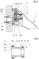
- connection 12 for a mixing valve In the mixer tap shown in Figure 1, only the battery body 1 is shown with a connection 12 for a mixing valve. A hollow extension 11 is formed on the battery body 1 at both end regions, a connection device for the supply line and a holder for the fitting body being formed in each hollow extension 11. In FIG. 1, only one connection device for the supply line for cold water is visibly shown, while the connection device provided opposite for the hot water supply line is covered by the hollow extension 11.
- a socket 2 with an eccentrically arranged threaded nipple 25 is screwed in a sealed manner.
- a cylinder guide 21 is formed in the end region of the connector 2 protruding from the building wall 5.
- Concentric to the cylinder guide 21, a thread 22 is arranged on the outer area, on which a guide and holding nut 23 is screwed.
- the guide and holding nut 23 has a free space 231 in the area of the eccentrically arranged threaded nipple 24, so that both parts can move freely with respect to one another.
- a cylinder guide 111 with a smaller diameter is arranged in the hollow extension 11 approximately coaxially with the cylinder guide 21.
- a sleeve 3 is axially displaceably mounted in the two cylinder guides 21 and 111, a circumferential collar 34 being provided at the end regions of the sleeve 3 on the outer jacket, the outer jacket surface 341 of which is spherical.
- Each collar 34 carries a circumferential annular groove 35, in which a round cord ring or O-ring made of rubber-elastic material is arranged radially projecting as a spherical sealing surface 31, 32.
- a sieve device 7 with a snap ring 71 is arranged in the bottom of the cylinder guide 21.
- a backflow preventer 6 is arranged downstream of the screening device 7 in a stepped through bore 33 of the sleeve 3.
- At least one radial screw 112 is provided in the hollow extension 11, which has a conical collar 233 when the battery body 1 is pushed on the guide and holding nut 23 cooperates, the radial screw 112 being provided with a correspondingly conical end face 1121.
- a spherical outer surface 232 with an enlarged diameter is provided, which in the plug-in position interacts with a bore 113 in the hollow shoulder 11 and provides the battery body 1 with guidance and holder.
- the spherical design of the outer surface 232 is therefore necessary so that the battery body 1 can still be adequately guided even when the connector 2 is not brought out at a right angle from the building wall.
- the hollow extension 11 When the radial screw 112 is screwed into the hollow extension 11, the hollow extension 11 is moved in the direction of the building wall 5 when it is in contact with the conical collar 231, a seal 114 being formed on the end face of the hollow extension 11, which seal tightly against the building wall 5 guaranteed.
- the mixer tap can be installed on the building wall as follows: First, the nozzle 2 are sealed with the threaded nipples 24 in the end pieces of the supply lines 4. For convenient screwing in, a hexagonal surface 251 is provided in the downstream end region of the threaded nipple 24 for attacking an Allen key. The rotational position of the end region of the connecting piece 2 protruding from the building wall 5 is then set with regard to the internal dimension of the battery body 1. Then the screening devices 7 introduced into the cylinder guides 21, the sleeves 3 with the non-return valves 6 inserted into the cylinder guides 21 and the guide and retaining nuts 23 screwed against the building wall 5.
- the battery body 1 with the two cylinder guides 111 arranged in the hollow projections 11 can be pushed onto the projecting area of the sleeves 3, the spherical outer surfaces of the two guide and retaining nuts 23 being received by the bores 113. Subsequently, the radial screw 112 is screwed against the conical collar 231 on each of the two hollow lugs 11, so that the battery body 1 with the two hollow lugs 11 is brought towards the building wall 5 for sealing purposes with the two seals 114 and is secured in the plug-in position. The mixer tap is then completely mounted on the building wall 5.
- the inflowing cold and warm water passes through the through opening in the threaded nipple 24 through the sieve device 7 and the backflow preventer 6 into a water supply channel 15, through which cold and hot water are fed separately to the mixing valve.
Landscapes
- Health & Medical Sciences (AREA)
- Life Sciences & Earth Sciences (AREA)
- Engineering & Computer Science (AREA)
- Hydrology & Water Resources (AREA)
- Public Health (AREA)
- Water Supply & Treatment (AREA)
- Domestic Plumbing Installations (AREA)
- Stabilization Of Oscillater, Synchronisation, Frequency Synthesizers (AREA)
- Ticket-Dispensing Machines (AREA)
- Joints Allowing Movement (AREA)
- Battery Mounting, Suspending (AREA)
- Formation And Processing Of Food Products (AREA)
Abstract
Description
- Die Erfindung betrifft eine Mischbatterie für Kalt- und Warmwasser, insbesondere für den Sanitärbereich, mit einem Batteriekörper, der mit Hohlansätzen zur Abdeckung der Anschlußstellen für die Versorgungsleitungen versehen ist, in denen jeweils ein Stutzen in einer Zylinderführung zum Wasseranschluß gedichtet und axial verschiebbar angeordnet ist, wobei der Batteriekörper in seiner Stecklage fixierbar ist.
- Eine derartige Mischbatterie ist aus der deutschen Offenlegungsschrift 17 84 504 bekannt. Bei dieser vorbekannten Ausbildung sind Anschlußnippel vorgesehen, die jeweils mit einem kolbenartigen, zwei O-Ringe tragenden Vorderteil in der Zylinderführung eines Hohlansatzes axial verschiebbar aufgenommen sind. Bei der Anmontage bzw. Installation der Mischbatterie kann es hierbei jedoch zu Schwierigkeiten kommen, wenn die Anschlußleitungen in der Gebäudewand Schiefstellungen aufweisen bzw. die Anschlußstücke nicht rechtwinklig aus der Gebäudewand herausgeführt sind.
- Der Erfindung liegt die Aufgabe zugrunde, die im Oberbegriff des Anspruchs 1 angegebene Mischbatterie zu verbessern und so auszubilden, daß insbesondere auch bei winkelmäßigen Fehlstellungen der Anschlußleitungen eine einfache Installation der Mischbatterie ermöglicht wird.
- Diese Aufgabe wird erfindungsgemäß dadurch gelöst, daß die Stutzen der Versorgungsleitungen stromabwärts ebenfalls jeweils eine der Zylinderführung in den Hohlansätzen zugeordnete Zylinderführung aufweist, der Anschluß der jeweiligen Versorgungsleitung über eine von beiden Zylinderführungen aufgenommene, mit balligen Dichtungsflächen versehene Hülse erfolgt, wobei auf dem Außenmantel der Stutzen mittels Gewinde jeweils eine Führungs- und Haltemutter vorgesehen ist, die bei der Installation an der Gebäudewand zur Anlage bringbar ist und den Batteriekörper in der Stecklage haltert.
- Weitere Ausgestaltungen der Erfindung sind in den Ansprüchen 2 bis 8 angegeben.
- Ein Ausführungsbeispiel der Erfindung ist in der Zeichnung dargestellt und wird im folgenden näher beschrieben. Es zeigt
- Figur 1
- eine an einer Gebäudewand installierte Mischbatterie in Draufsicht, teilweise geschnitten;
- Figur 2
- einen Teil der in Figur 1 dargestellten Mischbatterie mit weiter aus der Gebäudewand vorstehenden Stutzen:
- Figur 3
- die in Figur 1 gezeigte Hülse in vergrößerter Darstellung im Längsschnitt.
- Bei der in Figur 1 gezeigten Mischbatterie ist lediglich der Batteriekörper 1 dargestellt mit einem Anschluß 12 für ein Mischventil. An dem Batteriekörper 1 ist an beiden Endbereichen jeweils ein Hohlansatz 11 ausgebildet, wobei in jedem Hohlansatz 11 eine Anschlußvorrichtung für die Versorgungsleitung und eine Halterung für den Armaturenkörper gebildet ist. In Figur 1 ist lediglich die eine Anschlußvorrichtung für die Versorgungsleitung für Kaltwasser sichtbar dargestellt, während die gegenüberliegend vorgesehene Anschlußvorrichtung für die Warmwasserversorgungsleitung von dem Hohlansatz 11 verdeckt ist.
- In dem Endstück der an der Gebäudewand 5 angeordneten Versorgungsleitung 4 für Kaltwasser ist ein Stutzen 2 mit einem exzentrisch angeordneten Gewindenippel 25 gedichtet eingeschraubt. In dem von der Gebäudewand 5 vorstehenden Endbereich des Stutzens 2 ist eine Zylinderführung 21 ausgebildet. Konzentrisch zur Zylinderführung 21 ist am Außenbereich ein Gewinde 22 angeordnet, auf dem eine Führungs- und Haltemutter 23 aufgeschraubt ist. Die Führungs- und Haltemutter 23 hat dabei im Bereich des exzentrisch angeordneten Gewindenippels 24 einen Freiraum 231, so daß sich beide Teile zueinander entsprechend frei bewegen können. In dem Hohlansatz 11 ist etwa koaxial zur Zylinderführung 21 eine im Durchmesser kleinere Zylinderführung 111 angeordnet. In den beiden Zylinderführungen 21 und 111 ist eine Hülse 3 axial verschieblich gelagert, wobei an den Endbereichen der Hülse 3 am Außenmantel jeweils ein umlaufender Bund 34 vorgesehen ist, dessen Außenmantelfläche 341 ballig ausgebildet ist. Jeder Bund 34 trägt eine umlaufende Ringnut 35, in der ein Rundschnurring bzw. O-Ring aus gummielastischem Material radial vorstehend als ballige Dichtungsfläche 31,32 angeordnet ist. Durch die ballige Ausbildung der Außenmantelflächen 341 und der vorstehenden balligen Dichtungsflächen 31,32 der O-Ringe ist auch bei einer Schiefstellung bzw. nicht rechtwinkligen Herausführung des Stutzens 2 aus der Gebäudewand 5 ein dichter Anschluß der Mischbatterie gewährleistet.
In der Zylinderführung 21 ist im Grund eine Siebeinrichtung 7 mit einem Sprengring 71 angeordnet. Stromabwärts hinter der Siebeinrichtung 7 in einer gestuften Durchgangsbohrung 33 der Hülse 3 ist ein Rückflußverhinderer 6 angeordnet. - In dem Hohlansatz 11 ist außerdem jeweils wenigstens eine Radialschraube 112 vorgesehen, die bei aufgeschobenem Batteriekörper 1 mit einem konischen Kragen 233 der Führungs- und Haltemutter 23 zusammenwirkt, wobei die Radialschraube 112 mit einer entsprechend konischen Stirnfläche 1121 versehen ist. An dem der Gebäudewand 5 zugekehrten Endbereich der Führungs- und Haltemutter 23 ist eine im Durchmesser vergrößerte, ballige Mantelfläche 232 vorgesehen, die in der Stecklage mit einer Bohrung 113 im Hohlansatz 11 zusammenwirkt und dem Batteriekörper 1 Führung und Halterung vermittelt. Die ballige Ausbildung der Mantelfläche 232 ist deshalb erforderlich, damit auch bei einer nicht rechtwinkligen Herausführung des Stutzens 2 aus der Gebäudewand noch eine hinreichende Führung des Batteriekörpers 1 ermöglicht wird. Beim Eindrehen der Radialschraube 112 jeweils in den Hohlansatz 11 wird bei der Anlage an dem konischen Kragen 231 der Hohlansatz 11 in Richtung auf die Gebäudewand 5 bewegt, wobei an der Stirnseite des Hohlansatzes 11 jeweils eine Dichtung 114 ausgebildet ist, die einen dichten Abschluß zur Gebäudewand 5 gewährleistet.
- Die Installation der Mischbatterie an der Gebäudewand kann in folgender Weise vorgenommen werden:
Zunächst werden die Stutzen 2 mit den Gewindenippeln 24 in die Endstücke der Versorgungsleitungen 4 eingedichtet. Zum bequemen Einschrauben ist hierbei im stromabwärts gelegenen Endbereich des Gewindenippels 24 eine Sechskantfläche 251 für den Angriff eines Innensechskantschlüssels vorgesehen. Sodann wird die Drehstellung des aus der Gebäudewand 5 vorstehenden Endbereichs der Stutzen 2 im Hinblick auf das Stichmaß des Batteriekörpers 1 eingestellt. Danach werden die Siebeinrichtungen 7 in die Zylinderführungen 21 eingebracht, die Hülsen 3 mit den Rückflußverhinderern 6 in die Zylinderführungen 21 eingesetzt und die Führungs- und Haltemuttern 23 gegen die Gebäudewand 5 geschraubt. Nunmehr kann der Batteriekörper 1 mit den beiden in den Hohlansätzen 11 angeordneten Zylinderführungen 111 auf den vorstehenden Bereich der Hülsen 3 aufgeschoben werden, wobei die balligen Mantelflächen der beiden Führungs- und Haltemuttern 23 von den Bohrungen 113 aufgenommen werden. Anschließend wird an beiden Hohlansätzen 11 jeweils die Radialschraube 112 gegen den konischen Kragen 231 geschraubt, so daß hiermit der Batteriekörper 1 mit den beiden Hohlansätzen 11 in Richtung der Gebäudewand 5 zur abdichtenden Anlage mit den beiden Dichtungen 114 gebracht und in der Stecklage gesichert wird. Die Mischbatterie ist hiernach komplett an der Gebäudewand 5 montiert. Das zuströmende Kalt- und Warmwasser gelangt hierbei über die Durchgangsöffnung im Gewindenippel 24 durch die Siebeinrichtung 7 und den Rückflußverhinderer 6 jeweils in einen Wasserzuführungskanal 15, durch die getrennt Kalt- und Warmwasser dem Mischventil zugeführt wird.
Mit der vorstehend beschriebenen Einrichtung kann somit - bei einer entsprechenden Dimensionierung der Zylinderführungen 111,21 und der Länge der Hülse 3 - ein axialer Tiefenausgleich 20 und darüber hinaus auch ein Ausgleich von winkelmäßigen Fehlstellungen der Stutzen 2 erreicht werden.
Claims (8)
- Mischbatterie für Kalt- und Warmwasser, insbesondere für den Sanitärbereich, mit einem Batteriekörper, der mit Hohlansätzen zur Abdeckung der Anschlußstellen für die Versorgungsleitungen versehen ist, in denen jeweils ein Stutzen in einer Zylinderführung zum Wasseranschluß gedichtet und axial verschiebbar angeordnet ist, wobei der Batteriekörper in seiner Stecklage fixierbar ist, dadurch gekennzeichnet, daß die Stutzen (2) der Versorgungsleitungen (4) stromabwärts ebenfalls jeweils eine der Zylinderführung (111) in den Hohlansätzen (11) zugeordnete Zylinderführung (21) aufweisen, der Anschluß der jeweiligen Versorgungsleitung (4) über eine von beiden Zylinderführungen (21,111) aufgenommenen, mit balligen Dichtungsflächen (31,32) versehenen Hülse (3) erfolgt, wobei auf dem Außenmantel der Stutzen (2) mittels Gewinde (22) jeweils eine Führungs- und Haltemutter (23) vorgesehen ist, die bei der Installation an der Gebäudewand (5) zur Anlage bringbar ist und den Batteriekörper (1) in der Stecklage haltert.
- Mischbatterie nach Anspruch 1, dadurch gekennzeichnet, daß die Führungs- und Haltemutter (23) einen konischen Kragen (231) hat, an den die Fixiereinrichtung des Hohlansatzes (11) vorzugsweise eine im Hohlansatz (11) angeordnete Radialschraube (112) mit einer entsprechend konischen Stirnfläche (1121) angreift, wobei die Führungs- und Haltemutter (23) an der der Gebäudewand (5) zugekehrten Seite eine im Durchmesser vergrößerte, ballige Mantelfläche (232) für die Aufnahme und Führung einer entsprechenden Bohrung (113) im Hohlansatz (11) hat.
- Mischbatterie nach Anspruch 1 oder 2, dadurch gekennzeichnet, daß an der Stirnfläche der Hohlansätze (11) jeweils eine Dichtung (114) angeordnet ist, die den Anschlußbereich an der Gebäudewand (5) nach der Installation verschließt.
- Mischbatterie nach einem der Ansprüche 1 bis 3, dadurch gekennzeichnet, daß die stromabwärts angeordnete Dichtfläche (32) der Hülse (3) im Durchmesser verringert ausgebildet ist, wobei die Durchgangsbohrung (33) entsprechend gestuft ausgebildet ist und im erweiterten Bereich der Durchgangsbohrung (33) ein Rückflußverhinderer (6) angeordnet ist.
- Mischbatterie nach einem der Ansprüche 1 bis 4, dadurch gekennzeichnet, daß im Grund der Zylinderführung (21) des Stutzens (2) eine Siebeinrichtung (7) angeordnet ist.
- Mischbatterie nach einem der Ansprüche 1 bis 5, dadurch gekennzeichnet, daß der Stutzen (2) einen exzentrisch angeordneten Gewindenippel (24) zum Anschluß an die Versorgungsleitung (4) trägt, wobei die Führungs- und Haltemutter (23) im Bereich des Gewindenippels (24) einen Freiraum (231) hat, der eine beliebige Drehstellung des Gewindenippels (24) ermöglicht.
- Mischbatterie nach einem der Ansprüche 1 bis 6, dadurch gekennzeichnet, daß die balligen Dichtflächen (31,32) von Rundschnurringen aus gummielastischem Material gebildet sind, die radial aus der Mantelfläche der Hülse (3) vorstehen.
- Mischbatterie nach Anspruch 7, dadurch gekennzeichnet, daß die Hülse (3) an den beiden Endbereichen mit jeweils einem umlaufenden Bund (34) versehen ist, dessen Außenmantelfläche (341) ebenfalls jeweils ballig ausgebildet ist und in einer Ringnut (35) jeweils einen Rundschnurring trägt.
Applications Claiming Priority (2)
| Application Number | Priority Date | Filing Date | Title |
|---|---|---|---|
| DE19527986A DE19527986A1 (de) | 1995-07-31 | 1995-07-31 | Mischbatterie |
| DE19527986 | 1995-07-31 |
Publications (2)
| Publication Number | Publication Date |
|---|---|
| EP0757133A1 true EP0757133A1 (de) | 1997-02-05 |
| EP0757133B1 EP0757133B1 (de) | 1999-06-02 |
Family
ID=7768248
Family Applications (1)
| Application Number | Title | Priority Date | Filing Date |
|---|---|---|---|
| EP96110943A Expired - Lifetime EP0757133B1 (de) | 1995-07-31 | 1996-07-06 | Mischbatterie |
Country Status (6)
| Country | Link |
|---|---|
| EP (1) | EP0757133B1 (de) |
| JP (1) | JPH0941440A (de) |
| AT (1) | ATE180854T1 (de) |
| DE (2) | DE19527986A1 (de) |
| DK (1) | DK0757133T3 (de) |
| ES (2) | ES2135141T3 (de) |
Cited By (3)
| Publication number | Priority date | Publication date | Assignee | Title |
|---|---|---|---|---|
| WO1998041700A1 (en) * | 1997-03-14 | 1998-09-24 | Raf Rubinetterie S.P.A. | Improved bathtub wall tap assembly |
| WO2014154716A1 (de) * | 2013-03-25 | 2014-10-02 | Hansgrohe Se | Rohranschlussadapter und sanitärarmatur |
| EP4119734A1 (de) | 2021-07-13 | 2023-01-18 | Hansgrohe SE | Sanitärarmatur-wandanschlusseinrichtung und wandmontierbare sanitärarmatur |
Families Citing this family (6)
| Publication number | Priority date | Publication date | Assignee | Title |
|---|---|---|---|---|
| DE19743982C2 (de) * | 1997-04-17 | 2001-09-27 | Ideal Standard | Wandhängende Armatur mit Wandanschluß |
| DE10111579C2 (de) * | 2001-03-10 | 2003-06-26 | Hansa Metallwerke Ag | Sanitäre Wandarmatur |
| DE102005003051B4 (de) * | 2005-01-22 | 2009-10-29 | Hansa Metallwerke Ag | Sanitäre Waschtischarmatur |
| DE102008032185B3 (de) * | 2008-07-09 | 2009-08-27 | Ideal-Standard International Bvba | Sanitäre Wasserleitungsarmatur mit Unterputz-Montageeinheit |
| DE102013204163A1 (de) | 2013-03-11 | 2014-09-11 | Hansgrohe Se | Sanitärarmaturen-Anschlusssystem |
| CN107313483A (zh) * | 2017-08-08 | 2017-11-03 | 广州海鸥卫浴用品股份有限公司 | 挂墙式单把双控面盆水龙头 |
Citations (3)
| Publication number | Priority date | Publication date | Assignee | Title |
|---|---|---|---|---|
| US3438065A (en) * | 1966-07-22 | 1969-04-15 | Earl L Morris | Vandalproof,concealed anchor for plumbing fixture |
| DE1784504A1 (de) * | 1968-08-14 | 1971-08-19 | Grohe Armaturen Friedrich | Mischbatterie |
| EP0537652A1 (de) * | 1991-10-18 | 1993-04-21 | Friedrich Grohe Aktiengesellschaft | Rosette für einen Wandanschluss einer Mischbatterie |
-
1995
- 1995-07-31 DE DE19527986A patent/DE19527986A1/de not_active Withdrawn
-
1996
- 1996-07-06 EP EP96110943A patent/EP0757133B1/de not_active Expired - Lifetime
- 1996-07-06 AT AT96110943T patent/ATE180854T1/de not_active IP Right Cessation
- 1996-07-06 DE DE59602058T patent/DE59602058D1/de not_active Expired - Fee Related
- 1996-07-06 DK DK96110943T patent/DK0757133T3/da active
- 1996-07-06 ES ES96110943T patent/ES2135141T3/es not_active Expired - Lifetime
- 1996-07-11 JP JP8182319A patent/JPH0941440A/ja active Pending
- 1996-07-26 ES ES09602042U patent/ES1034782Y/es not_active Expired - Fee Related
Patent Citations (3)
| Publication number | Priority date | Publication date | Assignee | Title |
|---|---|---|---|---|
| US3438065A (en) * | 1966-07-22 | 1969-04-15 | Earl L Morris | Vandalproof,concealed anchor for plumbing fixture |
| DE1784504A1 (de) * | 1968-08-14 | 1971-08-19 | Grohe Armaturen Friedrich | Mischbatterie |
| EP0537652A1 (de) * | 1991-10-18 | 1993-04-21 | Friedrich Grohe Aktiengesellschaft | Rosette für einen Wandanschluss einer Mischbatterie |
Cited By (5)
| Publication number | Priority date | Publication date | Assignee | Title |
|---|---|---|---|---|
| WO1998041700A1 (en) * | 1997-03-14 | 1998-09-24 | Raf Rubinetterie S.P.A. | Improved bathtub wall tap assembly |
| WO2014154716A1 (de) * | 2013-03-25 | 2014-10-02 | Hansgrohe Se | Rohranschlussadapter und sanitärarmatur |
| DE102013205250B4 (de) | 2013-03-25 | 2019-03-14 | Hansgrohe Se | Rohranschlussadapter und Sanitärarmatur |
| EP4119734A1 (de) | 2021-07-13 | 2023-01-18 | Hansgrohe SE | Sanitärarmatur-wandanschlusseinrichtung und wandmontierbare sanitärarmatur |
| DE102021207445A1 (de) | 2021-07-13 | 2023-01-19 | Hansgrohe Se | Sanitärarmatur-Wandanschlusseinrichtung und wandmontierbare Sanitärarmatur |
Also Published As
| Publication number | Publication date |
|---|---|
| EP0757133B1 (de) | 1999-06-02 |
| ATE180854T1 (de) | 1999-06-15 |
| ES2135141T3 (es) | 1999-10-16 |
| JPH0941440A (ja) | 1997-02-10 |
| DK0757133T3 (da) | 1999-12-13 |
| DE19527986A1 (de) | 1997-02-06 |
| ES1034782U (es) | 1997-02-01 |
| DE59602058D1 (de) | 1999-07-08 |
| ES1034782Y (es) | 1997-07-01 |
Similar Documents
| Publication | Publication Date | Title |
|---|---|---|
| EP0681127B2 (de) | Wasserarmatur | |
| EP0389814B1 (de) | Anschlussvorrichtung für Mischarmaturen | |
| EP0757134B1 (de) | Mischbatterie | |
| DE102017101566B3 (de) | Schlauchanschlussanordnung, Verwendung einer Schlauchanschlussanordnung und Sanitärarmatur | |
| EP0119960B1 (de) | Sanitär-Armaturanschlussorgan | |
| EP0389810B1 (de) | Anschlussvorrichtung für Mischarmaturen | |
| EP0757133A1 (de) | Mischbatterie | |
| DE3826064C2 (de) | ||
| EP0537652A1 (de) | Rosette für einen Wandanschluss einer Mischbatterie | |
| EP0942104B1 (de) | Wasserarmatur | |
| EP1103749B1 (de) | Wasserarmatur | |
| DE4421387B4 (de) | Einlochmischbatterie | |
| DE202015101146U1 (de) | Wandarmatur | |
| EP0309397B1 (de) | Sanitäre Wasseranschlussanordnung | |
| EP1006243B1 (de) | Einheit aus Anschlussblock für Sanitärarmaturen und Spülblock | |
| EP1249649B1 (de) | Wasserarmatur | |
| DE102004037051B4 (de) | Mischbatterie mit Standanschluss | |
| DE10247066B4 (de) | Sanitärarmatur mit Anschlussstück | |
| EP0113444A1 (de) | Einlochmischbatterie | |
| WO2021244817A1 (de) | Sanitärarmatur | |
| DE19636851B4 (de) | Mischbatterie | |
| DE10032193B4 (de) | Rohrverbindung | |
| DE3218418C1 (de) | Bohr- und Absperrvorrichtung | |
| DE4102048A1 (de) | Sanitaerarmatur | |
| DE2418832C3 (de) | Vorrichtung zum Anschließen von Sanitärarmaturen |
Legal Events
| Date | Code | Title | Description |
|---|---|---|---|
| PUAI | Public reference made under article 153(3) epc to a published international application that has entered the european phase |
Free format text: ORIGINAL CODE: 0009012 |
|
| AK | Designated contracting states |
Kind code of ref document: A1 Designated state(s): AT CH DE DK ES FR GB IT LI NL SE |
|
| 17P | Request for examination filed |
Effective date: 19970426 |
|
| 17Q | First examination report despatched |
Effective date: 19970707 |
|
| GRAG | Despatch of communication of intention to grant |
Free format text: ORIGINAL CODE: EPIDOS AGRA |
|
| GRAG | Despatch of communication of intention to grant |
Free format text: ORIGINAL CODE: EPIDOS AGRA |
|
| GRAH | Despatch of communication of intention to grant a patent |
Free format text: ORIGINAL CODE: EPIDOS IGRA |
|
| GRAH | Despatch of communication of intention to grant a patent |
Free format text: ORIGINAL CODE: EPIDOS IGRA |
|
| GRAA | (expected) grant |
Free format text: ORIGINAL CODE: 0009210 |
|
| AK | Designated contracting states |
Kind code of ref document: B1 Designated state(s): AT CH DE DK ES FR GB IT LI NL SE |
|
| REF | Corresponds to: |
Ref document number: 180854 Country of ref document: AT Date of ref document: 19990615 Kind code of ref document: T |
|
| REG | Reference to a national code |
Ref country code: CH Ref legal event code: EP |
|
| PGFP | Annual fee paid to national office [announced via postgrant information from national office to epo] |
Ref country code: SE Payment date: 19990623 Year of fee payment: 4 |
|
| REF | Corresponds to: |
Ref document number: 59602058 Country of ref document: DE Date of ref document: 19990708 |
|
| PGFP | Annual fee paid to national office [announced via postgrant information from national office to epo] |
Ref country code: AT Payment date: 19990727 Year of fee payment: 4 |
|
| REG | Reference to a national code |
Ref country code: CH Ref legal event code: NV Representative=s name: BOVARD AG PATENTANWAELTE |
|
| ET | Fr: translation filed | ||
| ITF | It: translation for a ep patent filed | ||
| PGFP | Annual fee paid to national office [announced via postgrant information from national office to epo] |
Ref country code: DK Payment date: 19990916 Year of fee payment: 4 |
|
| GBT | Gb: translation of ep patent filed (gb section 77(6)(a)/1977) |
Effective date: 19990906 |
|
| REG | Reference to a national code |
Ref country code: ES Ref legal event code: FG2A Ref document number: 2135141 Country of ref document: ES Kind code of ref document: T3 |
|
| REG | Reference to a national code |
Ref country code: DK Ref legal event code: T3 |
|
| PLBE | No opposition filed within time limit |
Free format text: ORIGINAL CODE: 0009261 |
|
| STAA | Information on the status of an ep patent application or granted ep patent |
Free format text: STATUS: NO OPPOSITION FILED WITHIN TIME LIMIT |
|
| 26N | No opposition filed | ||
| PG25 | Lapsed in a contracting state [announced via postgrant information from national office to epo] |
Ref country code: GB Free format text: LAPSE BECAUSE OF NON-PAYMENT OF DUE FEES Effective date: 20000706 Ref country code: DK Free format text: LAPSE BECAUSE OF NON-PAYMENT OF DUE FEES Effective date: 20000706 Ref country code: AT Free format text: LAPSE BECAUSE OF NON-PAYMENT OF DUE FEES Effective date: 20000706 |
|
| PG25 | Lapsed in a contracting state [announced via postgrant information from national office to epo] |
Ref country code: SE Free format text: LAPSE BECAUSE OF NON-PAYMENT OF DUE FEES Effective date: 20000707 |
|
| PG25 | Lapsed in a contracting state [announced via postgrant information from national office to epo] |
Ref country code: LI Free format text: LAPSE BECAUSE OF NON-PAYMENT OF DUE FEES Effective date: 20000731 Ref country code: CH Free format text: LAPSE BECAUSE OF NON-PAYMENT OF DUE FEES Effective date: 20000731 |
|
| NLT1 | Nl: modifications of names registered in virtue of documents presented to the patent office pursuant to art. 16 a, paragraph 1 |
Owner name: FRIEDRICH GROHE AG & CO. KG |
|
| REG | Reference to a national code |
Ref country code: CH Ref legal event code: PFA Free format text: FRIEDRICH GROHE AKTIENGESELLSCHAFT TRANSFER- FRIEDRICH GROHE AG & CO. KG |
|
| REG | Reference to a national code |
Ref country code: FR Ref legal event code: CJ |
|
| PG25 | Lapsed in a contracting state [announced via postgrant information from national office to epo] |
Ref country code: NL Free format text: LAPSE BECAUSE OF NON-PAYMENT OF DUE FEES Effective date: 20010201 |
|
| GBPC | Gb: european patent ceased through non-payment of renewal fee |
Effective date: 20000706 |
|
| REG | Reference to a national code |
Ref country code: DK Ref legal event code: EBP |
|
| REG | Reference to a national code |
Ref country code: CH Ref legal event code: PL |
|
| EUG | Se: european patent has lapsed |
Ref document number: 96110943.6 |
|
| NLV4 | Nl: lapsed or anulled due to non-payment of the annual fee |
Effective date: 20010201 |
|
| PGFP | Annual fee paid to national office [announced via postgrant information from national office to epo] |
Ref country code: FR Payment date: 20020730 Year of fee payment: 7 |
|
| PGFP | Annual fee paid to national office [announced via postgrant information from national office to epo] |
Ref country code: ES Payment date: 20020821 Year of fee payment: 7 |
|
| PG25 | Lapsed in a contracting state [announced via postgrant information from national office to epo] |
Ref country code: ES Free format text: LAPSE BECAUSE OF NON-PAYMENT OF DUE FEES Effective date: 20030707 |
|
| PG25 | Lapsed in a contracting state [announced via postgrant information from national office to epo] |
Ref country code: FR Free format text: LAPSE BECAUSE OF NON-PAYMENT OF DUE FEES Effective date: 20040331 |
|
| REG | Reference to a national code |
Ref country code: FR Ref legal event code: ST |
|
| REG | Reference to a national code |
Ref country code: ES Ref legal event code: FD2A Effective date: 20030707 |
|
| PG25 | Lapsed in a contracting state [announced via postgrant information from national office to epo] |
Ref country code: IT Free format text: LAPSE BECAUSE OF NON-PAYMENT OF DUE FEES Effective date: 20050706 |
|
| PGFP | Annual fee paid to national office [announced via postgrant information from national office to epo] |
Ref country code: DE Payment date: 20050720 Year of fee payment: 10 |
|
| PG25 | Lapsed in a contracting state [announced via postgrant information from national office to epo] |
Ref country code: DE Free format text: LAPSE BECAUSE OF NON-PAYMENT OF DUE FEES Effective date: 20070201 |