EP0755052B1 - Optical recording medium - Google Patents
Optical recording medium Download PDFInfo
- Publication number
- EP0755052B1 EP0755052B1 EP96111774A EP96111774A EP0755052B1 EP 0755052 B1 EP0755052 B1 EP 0755052B1 EP 96111774 A EP96111774 A EP 96111774A EP 96111774 A EP96111774 A EP 96111774A EP 0755052 B1 EP0755052 B1 EP 0755052B1
- Authority
- EP
- European Patent Office
- Prior art keywords
- group
- carbon atoms
- wavelength
- layer
- recording medium
- Prior art date
- Legal status (The legal status is an assumption and is not a legal conclusion. Google has not performed a legal analysis and makes no representation as to the accuracy of the status listed.)
- Expired - Lifetime
Links
- 0 CC1SC(N=Nc(c(*)c2*)c(*)c(*)c2N)=NN1 Chemical compound CC1SC(N=Nc(c(*)c2*)c(*)c(*)c2N)=NN1 0.000 description 5
Images
Classifications
-
- G—PHYSICS
- G11—INFORMATION STORAGE
- G11B—INFORMATION STORAGE BASED ON RELATIVE MOVEMENT BETWEEN RECORD CARRIER AND TRANSDUCER
- G11B7/00—Recording or reproducing by optical means, e.g. recording using a thermal beam of optical radiation by modifying optical properties or the physical structure, reproducing using an optical beam at lower power by sensing optical properties; Record carriers therefor
- G11B7/24—Record carriers characterised by shape, structure or physical properties, or by the selection of the material
- G11B7/241—Record carriers characterised by shape, structure or physical properties, or by the selection of the material characterised by the selection of the material
- G11B7/242—Record carriers characterised by shape, structure or physical properties, or by the selection of the material characterised by the selection of the material of recording layers
- G11B7/244—Record carriers characterised by shape, structure or physical properties, or by the selection of the material characterised by the selection of the material of recording layers comprising organic materials only
- G11B7/246—Record carriers characterised by shape, structure or physical properties, or by the selection of the material characterised by the selection of the material of recording layers comprising organic materials only containing dyes
- G11B7/247—Record carriers characterised by shape, structure or physical properties, or by the selection of the material characterised by the selection of the material of recording layers comprising organic materials only containing dyes methine or polymethine dyes
- G11B7/2472—Record carriers characterised by shape, structure or physical properties, or by the selection of the material characterised by the selection of the material of recording layers comprising organic materials only containing dyes methine or polymethine dyes cyanine
-
- G—PHYSICS
- G11—INFORMATION STORAGE
- G11B—INFORMATION STORAGE BASED ON RELATIVE MOVEMENT BETWEEN RECORD CARRIER AND TRANSDUCER
- G11B7/00—Recording or reproducing by optical means, e.g. recording using a thermal beam of optical radiation by modifying optical properties or the physical structure, reproducing using an optical beam at lower power by sensing optical properties; Record carriers therefor
- G11B7/24—Record carriers characterised by shape, structure or physical properties, or by the selection of the material
- G11B7/241—Record carriers characterised by shape, structure or physical properties, or by the selection of the material characterised by the selection of the material
- G11B7/242—Record carriers characterised by shape, structure or physical properties, or by the selection of the material characterised by the selection of the material of recording layers
- G11B7/244—Record carriers characterised by shape, structure or physical properties, or by the selection of the material characterised by the selection of the material of recording layers comprising organic materials only
-
- C—CHEMISTRY; METALLURGY
- C09—DYES; PAINTS; POLISHES; NATURAL RESINS; ADHESIVES; COMPOSITIONS NOT OTHERWISE PROVIDED FOR; APPLICATIONS OF MATERIALS NOT OTHERWISE PROVIDED FOR
- C09B—ORGANIC DYES OR CLOSELY-RELATED COMPOUNDS FOR PRODUCING DYES, e.g. PIGMENTS; MORDANTS; LAKES
- C09B45/00—Complex metal compounds of azo dyes
- C09B45/34—Preparation from o-monohydroxy azo compounds having in the o'-position an atom or functional group other than hydroxyl, alkoxy, carboxyl, amino or keto groups
-
- G—PHYSICS
- G11—INFORMATION STORAGE
- G11B—INFORMATION STORAGE BASED ON RELATIVE MOVEMENT BETWEEN RECORD CARRIER AND TRANSDUCER
- G11B7/00—Recording or reproducing by optical means, e.g. recording using a thermal beam of optical radiation by modifying optical properties or the physical structure, reproducing using an optical beam at lower power by sensing optical properties; Record carriers therefor
- G11B7/24—Record carriers characterised by shape, structure or physical properties, or by the selection of the material
- G11B7/241—Record carriers characterised by shape, structure or physical properties, or by the selection of the material characterised by the selection of the material
- G11B7/242—Record carriers characterised by shape, structure or physical properties, or by the selection of the material characterised by the selection of the material of recording layers
- G11B7/244—Record carriers characterised by shape, structure or physical properties, or by the selection of the material characterised by the selection of the material of recording layers comprising organic materials only
- G11B7/246—Record carriers characterised by shape, structure or physical properties, or by the selection of the material characterised by the selection of the material of recording layers comprising organic materials only containing dyes
- G11B7/248—Record carriers characterised by shape, structure or physical properties, or by the selection of the material characterised by the selection of the material of recording layers comprising organic materials only containing dyes porphines; azaporphines, e.g. phthalocyanines
-
- G—PHYSICS
- G11—INFORMATION STORAGE
- G11B—INFORMATION STORAGE BASED ON RELATIVE MOVEMENT BETWEEN RECORD CARRIER AND TRANSDUCER
- G11B7/00—Recording or reproducing by optical means, e.g. recording using a thermal beam of optical radiation by modifying optical properties or the physical structure, reproducing using an optical beam at lower power by sensing optical properties; Record carriers therefor
- G11B7/24—Record carriers characterised by shape, structure or physical properties, or by the selection of the material
- G11B7/241—Record carriers characterised by shape, structure or physical properties, or by the selection of the material characterised by the selection of the material
- G11B7/242—Record carriers characterised by shape, structure or physical properties, or by the selection of the material characterised by the selection of the material of recording layers
- G11B7/244—Record carriers characterised by shape, structure or physical properties, or by the selection of the material characterised by the selection of the material of recording layers comprising organic materials only
- G11B7/249—Record carriers characterised by shape, structure or physical properties, or by the selection of the material characterised by the selection of the material of recording layers comprising organic materials only containing organometallic compounds
-
- G—PHYSICS
- G11—INFORMATION STORAGE
- G11B—INFORMATION STORAGE BASED ON RELATIVE MOVEMENT BETWEEN RECORD CARRIER AND TRANSDUCER
- G11B7/00—Recording or reproducing by optical means, e.g. recording using a thermal beam of optical radiation by modifying optical properties or the physical structure, reproducing using an optical beam at lower power by sensing optical properties; Record carriers therefor
- G11B7/24—Record carriers characterised by shape, structure or physical properties, or by the selection of the material
- G11B7/241—Record carriers characterised by shape, structure or physical properties, or by the selection of the material characterised by the selection of the material
- G11B7/252—Record carriers characterised by shape, structure or physical properties, or by the selection of the material characterised by the selection of the material of layers other than recording layers
- G11B7/257—Record carriers characterised by shape, structure or physical properties, or by the selection of the material characterised by the selection of the material of layers other than recording layers of layers having properties involved in recording or reproduction, e.g. optical interference layers or sensitising layers or dielectric layers, which are protecting the recording layers
Definitions
- the present invention relates to an optical recording medium, specifically to an optical recording medium which is capable of recording and reproducing in wavelengths of plural lasers.
- CD-R (CD-Recordable) has been developed and proposed as a write-once type optical recording medium which meets compact disk (hereinafter abbreviated as CD) standards (for example, Nikkei Electronics, No. 465, p. 107, January 23, 1989 issue, and OPTICAL DATA STORAGE DIGEST SERIES vol. 1, p. 45, 1989).
- CD compact disk
- This CD-R is laminated with a recording layer, a reflective layer and a protective layer in this order on a transparent resin substrate, and irradiation of a laser beam to the above recording layer at a high power causes physical or chemical change on the recording layer and allows information to be recorded thereon in the form of pits.
- the pits thus formed are irradiated with a laser beam at a low power to detect a change in a reflectance, whereby the information recorded in the pits can be reproduced.
- Such an optical recording medium uses a near infrared semiconductor laser having a wavelength falling in a range of 770 to 830 nm for recording and reproducing and meets CD standards such as a red book and an orange book, and therefore is characterized by that it is usable for CD players and CD-ROM players.
- optical recording media having such interchangeability that recording/reproducing or reproducing is possible with a red laser and recording/reproducing or reproducing is possible as well with a conventional near infrared semiconductor laser having a wavelength of 780 nm.
- CD and CD-ROM media have less dependence on wavelength in terms of a reflectance and can readily be reproduced with players for high density-media.
- conventional CD-R media use dyes in a recording layer, the optical characteristics depend greatly on wavelengths, and as a result, the reflectances of the CD-R media change to a large extent depending on the wavelengths.
- the reflectances to light beam having a wavelength of about 780 nm come up to 65 % or more
- the reflectances to red laser having a wavelength selected from a range of 620 to 690 nm are as small as about 10 % and the modulation degrees are small as well because a dye used in a recording layer has a large absorptivity and a small refractive index.
- a function-separating recording layer in which a dye layer having a high reflectance and causing no change of the state by heat energy of a laser beam and an organic substance layer having a light absorbing power are laminated in order is proposed in Japanese Patent Application Laid-Open No. 58-112794 (1983) as an example of an optical recording medium provided with two-layered dye.
- a medium in which a cyanine dye or merocyanine dye having a high reflectance and an organic light absorbing layer are laminated is proposed in Japanese Patent Application Laid-Open No. 60-239948 (1985).
- Dye recording layers having different optical constants are proposed in Japanese Patent Application Laid-Open No. 63-153192 (1988).
- a medium in which two kinds of organic dyes having different transmittance and absorptance to a laser beam having a certain wavelength are laminated is proposed in Japanese Patent Application Laid-Open No. 1-110193 (1989). Further, a recording layer comprising an organic two-layer having different transmittance or melting points to a laser beam having a certain wavelength is proposed in Japanese Patent Application Laid-Open No. 4-330649 (1992).
- these proposals are confined to improvement in a reflectance, optical degradation, high sensitivity recording and an error generating rate to a laser beam having a certain wavelength, and they are not optical recording media which are usable for recording and reproducing with plural kinds of laser beams.
- An object of the present invention is to solve the problems described above, that is, to provide an optical recording medium which can be recorded/reproduced or reproduced with light beam having a wavelength selected from wavelengths of 620 to 690 nm and which can be recorded/reproduced or reproduced based on the CD standards as well with light beam having a wavelength selected from conventional wavelengths of 770 to 830 nm and has good recording characteristics.
- the present invention relates to:
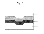
- Fig. 1 is a cross-sectional structural view of the optical recording medium, wherein;
- the optical recording medium of the present invention has a structure in which a dye layer is formed on a substrate and a reflective layer is provided thereon. Further, in order to protect the reflective layer, a protective layer may be provided on the reflective layer, or two sheets of media may be stuck together.
- the dye layer comprises a two-layer structure of a recording layer and an optical interference layer
- a laminating order of the recording layer and the optical interference layer may be reversed, and other layers may be present between the substrate and the dye layer or the optical interference layer or between the recording layer or the optical interference layer and the reflective layer.
- the materials for the substrate may be any one as long as it transmits rays having wavelengths for recording and reproducing. Used are, for example, polymer such as polycarbonate resins, vinyl chloride resins, acrylic resins such as polymethylmethacrylate, polystyrene resins and epoxy resins and inorganic materials such as glass. These materials for the substrate are molded into discoid substrates by injection molding. If necessary, guide grooves and pits for showing recording positions are formed on the surface of the substrate in some cases. Such guide grooves and pits are provided preferably in molding the substrate. They can be provided as well by forming a UV-cured resin layer on the substrate. Usually, when the optical recording medium is used for CD, it is a disc having a thickness of about 1.2 mm and a diameter of about 80 to 120 mm, and it has a hole having a diameter of about 15 mm in the center thereof.
- the dye layer is provided on the substrate, and the dye layer of the present invention contains a compound represented by Formula (1) or a metal complex thereof having a maximum absorption wavelength ( ⁇ max) falling in a range of less than 630 nm. Above all, preferred is the compound having a large refractive index and a small absorbance at wavelengths of 620 to 830 nm.
- ⁇ 1 in the optical interference layer containing a metal complex of the azo compound as a main component is preferably 0.15 or less
- an attenuation coefficient at ⁇ 2 is preferably 0.2 or less.
- the azo compound or the metal complex thereof used in the present invention is the azo compound represented by Formula (1) described above or the metal complex thereof.
- a halogen atom includes fluorine, chlorine, bromine and iodine, preferably fluorine, chlorine and bromine.
- An alkyl group is an unsubstitued or substitued alkyl group having 1 to 15 carbon atoms in total.
- the unsubstituted alkyl group includes a linear, branched or cyclic alkyl group.
- a substituent of the substituted alkyl group includes a halogen atom, an alkoxyl group, an alkoxyalkoxy group, an alkoxyalkoxyalkoxy group, an alkoxycarbonyl group, an alkoxycarbonyloxy group, an alkoxyalkoxycarbonyloxy group, a hydroxyl group, a hydroxyalkoxy group, a hydroxyalkoxyalkoxy group, a cyano group, an acyloxy group, an acyloxyalkoxy group, an acyloxyalkoxyalkoxy group, a sulfonic acid group, an alkylcarbonylamino group, an alkylsulfoamino group, a sulfonamide group,
- a linear or branched alkyl group is an alkyl group having 1 to 15 carbon atoms and includes, considering processability by coating on polycarbonate, acryl, epoxy or polyolefin substrates, methyl, ethyl, n-propyl, isopropyl, n-butyl, sec-butyl, t-butyl, n-pentyl, isopentyl, 2-methylbutyl, 1-methylbutyl, neopentyl, 1,2-dimethylpropyl, 1,1-dimethylpropyl, cyclopentyl, n-hexyl, 4-methylpentyl, 3-methylpentyl, 2-methylpentyl, 1-methylpentyl, 3,3-dimethylbutyl, 2,3-dimethylbutyl, 1,3-dimethylbutyl, 2,2-dimethylbutyl, 1,2-dimethylbutyl, 1,1-dimethylbutyl, 3-ethylbutyl
- An alkoxyalkyl group includes groups having 2 to 15 carbon atoms, such as methoxymethyl, ethoxymethyl, propoxymethyl, butoxymethyl, methoxyethyl, ethoxyethyl, propoxyethyl, butoxyethyl, n-hexyloxyethyl, 4-methylpentyloxyethyl, 1,3-dimethylbutoxyethyl, 2-ethylhexyloxyethyl, n-octyloxyethyl, 3,5,5-trimethylhexyloxyethyl, 2-methyl-1-isopropylpropoxyethyl, 3-methyl-1-isopropylbutoxyethyl, 2-ethoxy-l-methylethyl, 3-methoxybutyl, 3,3,3-trifluoropropoxyethyl and 3,3,3-trichloropropoxyethyl.
- alkoxyalkoxyalkyl group examples include -methoxyethoxyethyl, ethoxyethoxyethyl, propoxyethoxyethyl, butoxyethoxyethyl, hexyloxyethoxyethyl, 1,2-dimethylpropoxyethoxyethyl, 3-methyl-1-isobutylbutoxyethoxyethyl, 2-methoxy-1-methylethoxyethyl, 2-butoxy-1-methylethoxyethyl, 2-(2'-ethoxy-1'-methylethoxy)-1-methylethyl, 3,3,3-trifluoropropoxyethoxyethyl and 3,3,3-trichloropropoxyethoxyethyl.
- alkoxyalkoxyalkoxyalkyl group examples include methoxyethoxyethoxyethyl, ethoxyethoxyethoxyethyl, butoxyethoxyethoxyethyl, 2,2,2-trifluoroethoxyethoxyethoxyethyl and 2,2,2-trichloroethoxyethoxyethoxyethyl.
- alkoxycarbonylalkyl group examples include methoxycarbonylmethyl, ethoxycarbonylmethyl, butoxycarbonylmethyl, methoxycarbonyethyl, ethoxycarbonylethyl, butoxycarbonylethyl, 2,2,3,3-tetrafluoropropoxycarbonylmethyl and 2,2,3,3-tetrachloropropoxycarbonylmethyl.
- alkoxycarbonyloxyalkyl group examples include methoxycarbonyloxyethyl, ethoxycarbonyloxyethyl, butoxycarbonyloxyethyl, 2,2,2-trifluoroethoxycarbonyloxyethyl and 2,2,2-trichloroethoxycarbonyloxyethyl.
- alkoxyalkoxycarbonyloxyalkyl group includes methoxyethoxycarbonyloxyethyl, ethoxyethoxycarbonyloxyethyl, butoxyethoxycarbonyloxyethyl, 2,2,2-trifluoroethoxyethoxycarbonyloxyethyl and 2,2,2-trichloroethoxyethoxycarbonyloxyethyl.
- hydroxyalkyl group examples include 2-hydroxyethyl, 4-hydroxybutyl, 2-hydroxy-3-methoxypropyl, 2-hydroxy-3-chloropropyl, 2-hydroxy-3-ethoxypropyl, 3-butoxy-2-hydroxypropyl, 2-hydroxy-3-phenoxypropyl, 2-hydroxypropyl and 2-hydroxybutyl.
- hydroxyalkoxyalkyl group examples include hydroxyethoxyethyl, 2-(2'-hydroxy-1'-methylethoxy)-1-methylethyl, 2-(3'-fluoro-2'-hydroxypropoxy)ethyl and 2-(3'-chloro-2'-hydroxypropoxy)ethyl.
- hydroxyalkoxyalkoxyalkyl group examples include hydroxyethoxyethoxyethyl, [2'-(2"-hydroxy-1"-methylethoxy)-1'-methylethoxy]ethoxyethyl, [2'-( 2"-fluoro-1"-hydroxyethoxy)-1'-methylethoxy]ethoxyethyl and [2'-(2"-chloro-1"-hydroxyethoxy)-1'-methylethoxy]ethoxyethyl.
- cyanoalkyl group examples include 2-cyanoethyl, 2-cyanopropyl, 2-cyanobutyl, 4-cyanobutyl, 2-cyano-3-methoxypropyl, 2-cyano-3-chloropropyl, 2-cyano-3-ethoxypropyl, 3-butoxy-2-cyanopropyl and 2-cyano-3-phenoxypropyl.
- an acyloxyalkyl group examples include acetoxyethyl, propionyloxyethyl, butyryloxyethyl, valeryloxyethyl, 1-ethylpentylcarbonyloxyethyl, 2,4,4-trimethylpentylcarbonyloxyethyl, 3-fluoro-butyryloxyethyl and 3-chlorobutyryloxyethyl.
- an acyloxyalkoxyalkyl group examples include acetoxyethoxyethyl, propionyloxyethoxyethyl, valeryloxyethoxyethyl, 1-ethylpentylcarbonyloxyethoxyethyl, 2,4,4-trimethylpentylcarbonyloxyethoxyethyl, 2-fluoroprpionyloxyethoxyethyl and 2-chloropropionyloxyethoxyethyl.
- an acyloxyalkoxyalkoxyalkyl group include acetoxyethoxyethoxyethyl, propionyloxyethoxyethoxyethyl,valeryloxyethoxyethoxyethyl, 1-ethylpentylcarbonyloxyethoxyethoxyethyl, 2,4,4-trimethylpentylcarbonyloxyethoxyethoxyethyl, 2-fluoropropionyloxyethoxyethoxyethyl and 2-chloropropionyloxyethoxyethoxyethyl.
- halogenated alkyl group examples include chloromethyl, chloroethyl, 2,2,2-trifluoroethyl, trifluoromethyl, bromomethyl and iodomethyl.
- sulfonalkyl group examples include sulfonmethyl, sulfonethyl and sulfonpropyl.
- alkylcarbonylaminoalkyl group examples include methylcarbonylaminoethyl, ethylcarbonylaminoethyl, propylcarbonylaminoethyl, cyclohexylcarbonylaminoethyl and succiniminoethyl.
- alkylsulfoaminoalkyl group examples include methylsulfoaminoethyl, ethylsulfoaminoethyl and propylsulfoaminoethyl.
- sulfonamidealkyl group examples include sulfonamidemethyl, sulfonamidethyl and sulfonamidepropyl.
- alkylaminoalkyl group examples include N-methylaminomethyl, N,N-dimethylaminomethyl, N,N-diethylaminomethyl, N,N-dipropylaminomethyl and N,N-dibutylaminomethyl.
- aminoalkyl group examples include aminomethyl, aminoethyl and aminopropyl.
- alkylsulfonalkyl group examples include methylsulfonmethyl, ethylsulfonmethyl, butylsulfonmethyl, methylsulfonethyl, ethylsulfonethyl, butylsulfonethyl, 2,2,3,3-tetrafluoropropylsulfonmethyl and 2,2,3,3-tetrachloropropylsulfonmethyl.
- alkoxyl groups having the same substituents as the alkyl groups given above have, and include preferably lower alkoxyl groups such as methoxy, ethoxy, n-propoxy, isopropoxy, n-butoxy, isobutoxy, sec-butoxy, t-butoxy, n-pentyloxy, isopentyloxy, neopentyloxy and 2-methylbutoxy.
- aryl groups having the same substituents as the alkyl groups given above have, and include preferably phenyl, nitrophenyl, cyanophenyl, hydroxyphenyl, methylphenyl, trifluoromethylphenyl, naphthyl, nitronaphthyl, cyanonaphthyl, hydroxynaphthyl, methylnaphthyl and trifluoromethylnaphthyl.
- acyl groups having the same substituents as the alkyl groups given above have, and include preferably formyl, acetyl, ethylcarbonyl, n-propylcarbonyl, isopropylcarbonyl, n-butylcarbonyl, isobutylcarbonyl, sec-butylcarbonyl, t-butylcarbonyl, n-pentylcarbonyl, isopentylcarbonyl, neopentylcarbonyl, 2-methylbutylcarbonyl and nitrobenzylcarbonyl.
- alkylcarboxyl groups having the same substituents as the alkyl groups given above have, and include preferably lower alkylcarboxyl groups such as methylcarboxyl, ethylcarboxyl, n-propylcarboxyl, isopropylcarboxyl, n-butylcarboxyl, isobutylcarboxyl, sec-butylcarboxyl, t-butylcarboxyl, n-pentylcarboxyl, isopentylcarboxyl, neopentylcarboxyl and 2-methylbutylcarboxyl.
- lower alkylcarboxyl groups such as methylcarboxyl, ethylcarboxyl, n-propylcarboxyl, isopropylcarboxyl, n-butylcarboxyl, isobutylcarboxyl, sec-butylcarboxyl, t-butylcarboxy
- a substituted or unsubstituted aralkyl group are aralkyl groups having the same substituents as the alkyl groups given above have, and include preferably benzyl, nitrobenzyl, cyanobenzyl, hydroxybenzyl, methylbenzyl, trifluoromethylbenzyl, naphthylmethyl, nitronaphthylmethyl, cyanonaphthylmethyl, hydroxynaphthylmethyl, methylnaphthylmethyl and trifluoromethylnaphthylmethyl.
- alkylcarbonylamino groups having the same substituents as the alkyl groups given above have, and include preferably lower alkylcarbonylamino groups such as acetylamino, ethylcarbonylamino, n-propylcarbonylamino, isopropylcarbonylamino, n-butylcarbonylamino, isobutylcarbonylamino, sec-butylcarbonylamino, t-butylcarbonylamino, n-pentylcarbonylamino, isopentylcarbonylamino, neopentylcarbonylamino, 2-methylbutylcarbonylamino, cyclohexylcarbonylamino and succinimino.
- lower alkylcarbonylamino groups such as acetylamino, ethylcarbonylamino, n-propylcarbonylamino, isopropylcarbonylamino, n-
- alkylsulfoamino groups having the same substituents as the alkyl groups given above have, and include preferably lower alkylsulfoamino groups such as methylsulfoamino, ethylsulfoamino, n-propylsulfoamino, isopropylsulfoamino, n-butylsulfoamino, isobutylsulfoamino, sec-butylsulfoamino, t-butylsulfoamino, n-pentylsulfoamino, isopentylsulfoamino, neopentylsulfoamino, 2-methylbutylsulfoamino and cyclohexylsulfoamino.
- lower alkylsulfoamino groups such as methylsulfoamino, ethylsulf
- alkylamino groups having the same substituents as the alkyl groups given above have, and include preferably lower alkylamino groups such as N-methylamino, N,N-dimethylamino, N,N-diethylamino, N,N-dipropylamino and N,N-dibutylamino.
- alkylsulfonyl groups having the same substituents as the alkyl groups given above have, and include preferably lower alkylsulfonyl groups such as methylsulfonyl, ethylsulfonyl, n-propylsulfonyl, isopropylsulfonyl, n-butylsulfonyl, isobutylsulfonyl, sec-butylsulfonyl, t-butylsulfonyl, n-pentylsulfonyl, isopentylsulfonyl, neopentylsulfonyl, 2-methylbutylsulfonyl, 2-hydroxyethylsulfonyl and 2-cyanoethylsulfonyl.
- lower alkylsulfonyl groups such as methylsulfonyl, ethylsulfonyl,
- alkenyl groups having the same substituents as the alkenyl groups given above have, and include preferably lower alkenyl groups such as propenyl, 1-butenyl, isobutenyl, 1-pentenyl, 2-pentenyl, 2-methyl-1-butenyl, 3-methyl-1-butenyl, 2-methyl-2-butenyl, 2,2-dicyanovinyl, 2-cyano-2-methylcarboxylvinyl and 2-cyano-2-methylsulfonvinyl.
- alkylthio groups having the same substituents as the alkyl groups given above have, and include preferably lower alkylthio groups such as methylthio, ethylthio, n-propylthio, isopropylthio, n-butylthio, isobutylthio, sec-butylthio, t-butylthio, n-pentylsthio, isopentylthio, neopentylthio, 2-methylbutylthio and methylcarboxylethylthio.
- lower alkylthio groups such as methylthio, ethylthio, n-propylthio, isopropylthio, n-butylthio, isobutylthio, sec-butylthio, t-butylthio, n-pentylsthio, isopentylthio, neopentylthio, 2-methyl
- alkylazomethine groups having the same substituents as the alkyl groups given above have, and include preferably lower alkylazomethine groups such as methylazomethine, ethylazomethine, n-propylazomethine, isopropylazomethine, n-butylazomethine, isobutylazomethine, sec-butylazomethine, t-butylazomethine, n-pentylazomethine, isopentylazomethine, neopentylazomethine, 2-methylbutylazomethine and hydroxyethylazomethine.
- lower alkylazomethine groups such as methylazomethine, ethylazomethine, n-propylazomethine, isopropylazomethine, n-butylazomethine, isobutylazomethine, sec-butylazomethin
- alkylaminosulfonyl groups having the same substituents as the alkyl groups given above have, and include preferably lower alkylaminosulfonyl groups such as N-methylaminosulfonyl, N-ethylaminosulfonyl, N-(n-propyl)aminosulfonyl, N-(isopropyl)aminosulfonyl, N-(n-butyl)aminosulfonyl, N-(isobutyl)aminosulfonyl, N-(secbutyl)aminosulfonyl, N-(t-butyl)aminosulfonyl, N-(n-pentyl)aminosulfonyl, N-(isopentyl)aminosulfonyl, N-(neopentyl)aminosulfonyl, N-(2-methyl
- the compound of the present invention represented by Formula (1) can be produced in the following manner by known methods. That is, an amine component represented by the following Formula (4) is turned into an azo component, which is added to a solution of a coupling component represented by the following Formula (5) to carry out a coupling reaction, whereby the azo compound represented by Formula (1) is obtained: wherein R 1 to R 7 , X and Y are synonymous with those described in Formula (1).
- the metal complex of the azo compound described above can be produced by known methods, for example, a method described in Furukawa, Analytica Chimica Acta 140 (1982), 281 to 289.
- Preferred as a metal for forming the metal complex of the azo compound are, for example, metals such as nickel, cobalt, iron, ruthenium, rhodium, palladium, copper, osmium, iridium, platinum, zinc and magnesium, and more preferred are nickel, cobalt, copper, palladium, iron and zinc.
- the metal complexes of the azo compounds may be used alone or in a mixture of the plural compounds.
- a phthalocyanine compound contained in the dye layer is the phthalocyanine compound represented by Formula (2) having an absorption maximum in a wavelength range of 680 to 900 nm and having preferably a large refractive index and a small absorbance in a wavelength range of 770 to 830 nm.
- the optical constants (refractive index n and attenuation coefficient k) required for the recording layer containing the phthalocyanine compound are 1.8 or more for n and 0.04 to 0.20 for k at the wavelength ⁇ 1 of the laser beams, and 1.1 or more for n and 0.04 to 0.6 for k at the wavelength ⁇ 2 .
- n is a smaller value than the above range at the wavelength ⁇ 1 , it is difficult to obtain the reflectance and the modulation degree which satisfy the CD standards.
- the value of n smaller than the above range also at the wavelength ⁇ 2 makes it difficult to obtain the reflectance needed for reading signals accurately.
- the value of k exceeding 0.20 at the wavelength ⁇ 1 lowers the reflectance and makes it difficult to satisfy the CD standards, and the value of k less than 0.04 makes recording impossible.
- the value of k exceeding 0.6 at the wavelength ⁇ 2 not only increases the absorbance too much and does not provide the reflectance needed for reproduction but also makes the signals to be liable to change by reproducing light. Accordingly, it is not suited to practical use.
- k has to be 0.04 or more.
- the hydrocarbon group includes a saturated hydrocarbon group such as methyl, ethyl, butyl, pentyl, hexyl, heptyl, octyl, nonyl, decyl, dodecyl, cyclohexyl and dimethylcyclohexyl, and unsaturated hydrocarbon group such as ethenyl, butenyl, hexenyl, octenyl, dodecenyl, butynyl, heptynyl, phenyl, methylphenyl, butylphenyl and hexylphenyl.
- These hydrocarbon groups may be linear, branched or cyclic and may be substituted with halogen, an amino group, a cyano group, an ether group or hydroxyl group.
- a halogen atom includes fluorine, chlorine, bromine and iodine.
- substitution positions of the substituents of Y 1 to Y 8 and A 1 to A 4 bonded to the benzene rings constituting a phthalocyanine ring shall not specifically be restricted, and the kind and number of the substituents may be different for the four benzene rings in the molecule.
- the divalent metal atom represented by M includes Cu, Zn, Fe, Co, Ni, Ru, Pd, Pt, Mg, Ti, Be, Ca, Ba, Pb and Cd
- one-substituted trivalent metal includes Al-Cl, Al-Br, Ga-Cl, Ga-Br, In-Cl, In-Br, Ti-Cl, Ti-Br, Al-C 6 H 5 , Al-C 6 H 4 (CH 3 ), In-C 10 H 7 , Mn(OH), Mn(OC 6 H 5 ), Mn(OSi(CH 3 ) 3 ), FeCl and RuCl
- two-substituted tetravalent metal includes CrCl 2 , SiCl 2 , CeBr 2 , SnCl 2 , TiCl 2 , Mn(OH) 2 , Sn(OH) 2 , TiR 2 , CrR 2 , SiR 2 , SnR 2 , GeR 2 (R represents an alkyl group
- the concrete examples of the above phthalocyanine compound include the following compounds (Formulas (a) to (c)). To be detailed, given are the compounds described in Japanese Patent Application Laid-Open No. 3-62878 (1991), Japanese Patent Application Laid-Open No. 3-141582 (1991) and Japanese Patent Application Laid-Open No. 3-215466 (1991), and they can be synthesized by the methods described in these publications.
- phthalocyanine compounds may be used alone or in a mixture of the plural compounds.
- a method for providing the dye layer in the present invention includes, for example, dipping, spraying, spin coating, casting, sputtering, chemical deposition and vacuum deposition, and the spin coating is preferred since it is simple.
- a coating solution prepared by dissolving or dispersing the azo compound represented by Formula (1) or the metal complex thereof and/or the phthalocyanine compound represented by Formula (2) (hereinafter referred to as the dye) in a range of 0.05 to 30 weight %, preferably 0.5 to 20 weight % is used.
- a solvent which does not damage the substrate is preferably selected.
- the solvent includes, for example, alcohol series solvents such as methanol, ethanol, isopropanol, octafluoropentanol, allyl alcohol, methyl cellosolve, ethyl cellosolve and tetrafluoropropanol, aliphatic or alicyclic hydrocarbon series solvents such as hexane, heptane, octane, decane, cyclohexane, methylcyclohexane, ethylcyclohexane and dimethylcyclohexane, aromatic hydrocarbon series solvents such as toluene, xylene and benzene, halogenated hydrocarbon solvents such as carbon tetrachloride, chloroform, tetrachloroethane and dibromoethane, ether solvents such as diethyl ether, dibutyl ether, diisopropyl ether and dioxane, ket
- the dye layer comprises a two-layer structure of the recording layer and the optical interference layer
- the phthalocyanine compound used in the recording layer and the azo compound or the metal complex thereof used in the optical interference layer each dissolved in different polar solvents are used, and each is preferably not dissolved in the other solvent.
- the azo compound or the metal complex (dye) thereof used in the optical interference layer is dissolved in high polar solvents, for example, alcohol solvents and water, and coated, and the phthalocyanine compound (dye) used in the recording layer is dissolved in a low polar solvent, for example, aliphatic or alicyclic hydrocarbon solvents, aromatic hydrocarbon solvents, carbon tetrachloride and ether solvents, and coated.
- solvents for coating and forming the respective dye layers are preferably an aliphatic or alicyclic hydrocarbon solvent and a mixed solvent thereof with other solvents, and an alcohol solvent and a mixed solvent thereof with other solvents.
- a combination of the dyes soluble in the respective solvents is particularly desired.
- a film thickness of the dye layer shall not specifically be restricted and is preferably 50 to 300 nm.
- the film thickness of the dye layer smaller than 50 nm not only makes recording impossible or causes distortion on recording signals because of large heat diffusion, but also decreases signal amplitudes. As a result the CD standards are not satisfied. Meanwhile, the film thickness larger than 300 nm lowers the reflectance to deteriorate the reproducing signal characteristics.
- an average film thickness of the optical interference layer satisfies the following equation at the wavelengths of ⁇ 1 and ⁇ 2 and preferably is a thickness at which the reflectance becomes larger at the respective laser wavelengths: 70 ⁇ ni ⁇ di ⁇ 300 wherein ni is a refractive index of the optical interference layer, and di is a film thickness of the optical interference layer.
- ni ⁇ di is less than 70
- the reflectance to light having the wavelength ⁇ 2 is less than 15 %, and the modulation degree decreases as well.
- ni ⁇ di exceeds 300
- the reflectance to light having the wavelength ⁇ 1 is less than 65 %.
- additives such as a quencher, a thermal decomposition promotor of dyes, a UV absorber and an adhesive may be blended with the dyes described above, or groups having such effects may be introduced as substituents into the dyes.
- Preferred as the quencher are metal complexes based on acetyl acetonates, bisdithio- ⁇ -diketones, bisdithiols such as bisphenyldithiol, thiocatechols, salicylaldehyde oximes and thiobisphenolates. Further, amines are suitable as well.
- the thermal decomposition promoter shall not specifically be restricted as long as promotion of thermal decomposition of the dyes can be confirmed by means of thermogravimetric analysis (TG analysis), and includes metal compounds such as metalic antiknocking agents, metallocene compounds and acetylacetonato metal complexes.
- TG analysis thermogravimetric analysis
- binders, leveling agents, and defoaming agents may be used as well in combination, if necessary.
- the preferred binder includes polyvinyl alcohol, polyvinyl pyrrolidone, nittrocellulose, cellulose acetate, ketone resins, acrylic resins, polystyrene resins, urethane resins, polyvinyl butyral, polycarbonate, polyolefins, and the like.
- dyes other than those described above may be added as well in order to improve recording characteristics.
- the examples of the dyes include pentamethinecyanine dyes, heptamethinecyanine dyes, squalillium dyes, naphthoquinone dyes, azo dyes, naphthalocyanine dyes, phthalocyanine dyes and anthraquinone dyes.
- a blending ratio of these dyes falls in a level of 0.1 to 10 %.
- a layer comprising inorganic substances or polymers may be provided on the substrate in order to improve the solvent resistance of the substrate, reflectance and the recording sensitivity.
- the content of the azo compound represented by Formula (1) or the metal complex thereof and/or the phthalocyanine compound represented by Formula (2) in the dye layer is 30 % or more, preferably 60 % or more. It may be substantially 100 %.
- a reflective layer having a thickness of preferably 50 to 300 nm is formed on the dye layer described above.
- Substances providing sufficiently high reflectances at wavelengths of reproducing lights for example, metals such as Au, Al, Ag, Cu, Ti, Cr, Ni, Pt, Ta, Cr and Pd can be used as a material for the reflective layer alone or in the form of alloys.
- Au and Al have the high reflectances and therefore are suitable to the material for the reflective layer.
- the following ones may be contained.
- a substance containing Au as a main component is suitable since the reflective layer having a high reflectance can readily be obtained.
- main component means a component having a content of 50 % or more.
- a multilayer film may be formed for the reflective layer with materials other than metals by laminating a thin film having a low refractive index and a thin film having a high refractive index after the other.
- Methods for forming the reflective layer include, for example, sputtering, ion plating, chemical deposition and vacuum deposition. Further, a known inorganic or organic intermediate layer and an adhesive layer may be provided on the substrate or under the reflective layer in order to improve the reflectance and the recording characteristics.
- a protective layer is formed on the reflective layer in order to protect the dye layer and the reflective layer. Two sheets of the media may be stuck together.
- the organic materials include thermoplastic resins, thermosetting resins, electron beam-curing resins, and UV-curing resins.
- the inorganic materials include SiO 2 , SiN 4 , MgF 2 , and SnO 2 .
- the protective layer can be formed by applying a coating solution prepared by dissolving a thermoplastic resin or a thermosetting resin in a suitable solvent, and drying it. A UV curing resin is applied as it is or as a solution prepared by dissolving it in a suitable solvent, and it is irradiated with UV rays to cure, whereby the protective layer can be formed.
- Acrylate resins such as, for example, urethane acrylates, epoxy acrylates and polyester acrylates can be used as the UV-curing resin. These materials may be used alone or in a mixture, and they may be used not only in a single layer film but also in a multilayer film.
- Coating methods such as spin coating and casting, and methods such as sputtering and chemical deposition are used as a method for forming the protective layer as is the case with the recording layer.
- the spin coating is preferred.
- the film thickness of the protective layer falls in a range of 0.1 to 100 ⁇ m. In the present invention, however, it is 3 to 30 ⁇ m, preferably 5 to 20 ⁇ m.
- printing such as labeling can be applied on the protective layer.
- a film of a UV-curing resin or an inorganic film may be formed on a specular side of the substrate in order to protect the surface and prevent dusts from sticking thereon.
- the optical recording medium of the present invention thus obtained can record and reproduce by focusing laser beams on the dye layer.
- Signals used in recording include, for example, EMF modulation signals used for CD.
- the medium of the present invention can be recorded and reproduced with laser beams having a wavelength of about 780 nm since the reflectance of 65 % or more to light having a wavelength selected from 770 to 830 nm can be obtained. Further, recorded information can be reproduced with commercial CD and CD-ROM players. The characteristics of the signals reproduced satisfy the orange book standards which are the standards of CD-R.
- the medium of the present invention provides a reflectance of 15 % or more to light having a wavelength falling in a range of 620 to 690 nm and therefore can be reproduced with an optical disc player for high density recording media loaded with a laser having a wavelength selected from arrange of 620 to 690 nm.
- Light used for players for high density recording media in the next age has a wavelength falling in a range of 620 to 690 nm.
- Lasers having wavelengths falling in this range include dye lasers, which have wavelengths to be selected in a wide range of a visible ray region, and a helium-neon laser having a wavelength of 633 nm.
- semiconductor lasers which are put into practical use have a wavelength of, for example, 635 nm, 650 nm or about 680 nm.
- the medium of the present invention can be recorded as well with light having a wavelength selected from a range of 620 to 690 nm.
- the azo compound (1-19) of 0.2 g shown in Table-1 out of the azo compounds represented by Formula (1) and the phthalocyanine compound of 0.02 g represented by the chemical formula (a-11) described previously were dissolved in diacetone alcohol (produced by Tokyo Kasei K.K.) of 10 ml to prepare a dye solution.
- diacetone alcohol produced by Tokyo Kasei K.K.
- Used as a substrate was a disc (made of polycarbonate resin) having a diameter of 120 mm and a thickness of 1.2 mm with a spiral pre-groove (track pitch: 1.6 ⁇ m).
- the dye solution was spin-coated on this substrate at a revolution of 1500 rpm and dried at 70°C for 2 hours to form a recording layer.
- Au was sputtered on this recording layer with a sputtering equipment (CDI-900: manufactured by Balzers Co., Ltd.) to form a reflective layer having a thickness of 100 nm.
- Sputtering was carried out at a gas pressure of 1.33 Pa (1.0 x 10 -2 Torr).
- a UV-curing resin SD-17 (manufactured by Dainippon Ink Chemical Ind. Co., Ltd.) was spin-coated on the reflective layer and then irradiated with UV rays to form a protective layer having a thickness of 6 ⁇ m.
- this recorded sample was reproduced and evaluated with a commercial CD player having a reproducing wavelength of 780 nm to find that the sample showed good recording characteristics.
- Optical recording media were produced in the same manner as described in Example 1, except that the azo compounds described in Table-1 and the phthalocyanine compounds represented by the chemical formulas (a-10 to 11) described previously were used in combination.
- Example 2 Recording was carried out on the optical recording media thus obtained in the same manner as that in Example 1 at a linear velocity of 5.6 m/s and a laser power of 10 mW with the optical disc evaluation apparatus DDU-1000 (manufactured by Pulstec Ind. Co., Ltd.) loaded with the red semiconductor laser head having a wavelength of 680 nm and the EFM encoder (manufactured by Kenwood Co., Ltd.). After recording, the same measurements as those in Example 1 were carried out to find that the good recording characteristics were shown in any cases.
- a solution prepared by dissolving 0.8 g of the phthalocyanine compound represented by the chemical formula (b-7) described previously in dimethylcyclohexane (produced by Tokyo Kasei K.K.) of 40 ml was used to form a recording layer by spin-coating.
- the azo compound (1-31) described in Table-1 was used to form an interference layer on this recording layer on the same conditions as those in Example 1, whereby an optical recording medium comprising two layers of the interference layer and the recording layer was prepared.
- the signals were reproduced with an evaluation apparatus loaded with a red semiconductor laser head having a wavelength of 680 nm to find that such good recording characteristics as the reflectance of 31 % were shown.
- Optical recording media were produced in the same manner as that described in Example 29, except that the azo compounds described in Table-1 and the phthalocyanine compounds represented by the chemical formulas (b-1 to c-10) described previously were used in combination.
- the signals were reproduced with the evaluation apparatus loaded with the red semiconductor laser head having a wavelength of 680 nm to find that such good recording characteristics as the reflectances of 30 % or more were shown in the respective cases.
- the signals were reproduced with the evaluation apparatus loaded with the red semiconductor laser head having a wavelength of 680 nm to find that such good recording characteristics as the reflectance of 30 % were shown.
- An optical recording medium was produced in the same manner as that described in Example 47, except that the azo compound (1-39) described in Table-1 and the phthalocyanine compound (b-7) represented by the chemical formula described previously were used in combination.
- the signals were reproduced with the evaluation apparatus loaded with the red semiconductor laser head having a wavelength of 680 nm to find that such good recording characteristics as the reflectance of 30 % were shown.
- the metal complex (1-93) of the azo compound of 0.2 g shown in Table-1 out of the metal complexes of the azo compounds represented by Formula (1) and 0.02 g of the phthalocyanine compound (a-10) represented by the chemical formula described previously were dissolved in 2,2,3,3-tetrafluoro-1-propanol of 10 ml to prepare a dye solution.
- Used as a substrate was a disc having a diameter of 120 mm and a thickness of 1.2 mm, which was made of polycarbonate resin and had a spiral pre-groove (track pitch: 1.6 ⁇ m).
- the dye solution was spin-coated on this substrate at a revolution of 1500 rpm and dried at 70°C for 2 hours to form a recording layer.
- Au was sputtered on this recording layer with the sputtering equipment (CDI-900: manufactured by Balzers Co., Ltd.) to form a reflective layer having a thickness of 100 nm.
- Sputtering was carried out at a gas pressure of 1.33 Pa (1.0 x 10 -2 Torr).
- the UV-curing resin SD-17 manufactured by Dainippon Ink Chemical Ind. Co., Ltd.
- EFM signals were recorded on this optical recording medium at a linear velocity of 2.8 m/s and a laser power of 8 mW with a writer (CDD-521: manufactured by Philiphs Co., Ltd.).
- the signals were reproduced with a commercial CD player (YAMAHA CDX-1050; laser wavelength: 786 nm) to determine the reflectance, the error rate and the modulation degree. As a result, the distortion of the reproducing wave form was small, and therefore the good values satisfying the orange book standards were shown.
- the signals recorded on this medium were reproduced with the optical disc evaluation apparatus (DDU-1000: manufactured by Pulstec Ind.
- the signals recorded on the medium with the above drive (DDU-1000) having a wavelength of 680 nm were reproduced with the commercial CD player (YAMAHA CDX-1050; laser wavelength: 786 nm) to determine the reflectance, the error rate and the I3/Itop.
- the good values satisfying the orange book standards were shown in any cases.
- Optical recording media were produced in the same manner as that described in Example 49, except that the metal complexes of the azo compounds described in Table-1 out of the metal complexes of the azo compounds represented by Formula (1), and the phthalocyanine compounds represented by the chemical formulas (a-10 to 11) described previously were used in combination (shown in Table 3).
- the metal complex (1-89) of the azo compound of 0.2 g shown in Table-1 out of the metal complexes of the azo compounds represented by Formula (1) was dissolved in 2,2,3,3-tetrafluoro-1-propanol of 10 ml to prepare a dye solution 1.
- Used as a substrate was a disc having a diameter of 120 mm and a thickness of 1.2 mm, which was made of polycarbonate resin and had a spiral pre-groove (170 nm thick, 0.5 ⁇ m wide, track pitch: 1.6 ⁇ m).
- the dye solution 1 was spin-coated on this substrate at a revolution of 1500 rpm and dried at 70°C for 3 hours to form a dye optical interference layer.
- the refractive index was 1.9 and the attenuation coefficient was 0.05 at 780 nm; the refractive index was 2.1 and the attenuation coefficient was 0.04 at 680 nm; and the refractive index was 2.5 and the attenuation coefficient was 0.10 at 635 nm.
- the products (ni ⁇ di) of the refractive indices and the film thickness at 780, 680 and 635 nm were 152, 168 and 200, respectively.
- a dye solution 2 prepared by dissolving 0.25 g of the phthalocyanine compound (c-2) represented by the chemical formula described previously in 1,2-dimethylcyclohexane of 10 ml was spin-coated at a revolution of 1600 rpm and dried at 70°C for 2 hours to form a recording layer.
- the refractive index was 2.2 and the attenuation coefficient was 0.08 at 780 nm; the refractive index was 1.2 and the attenuation coefficient was 0.49 at 680 nm; and the refractive index was 1.2 and the attenuation coefficient was 0.34 at 635 nm.
- EFM signals were recorded on this optical recording medium at a linear velocity of 2.8 m/s and a laser power of 8 mW with the writer (CDD-521: manufactured by Philiphs Co., Ltd.).
- the signals were reproduced with the commercial CD player (YAMAHA CDX-1050; laser wavelength: 786 nm) to determine the reflectance, the error rate and the modulation degree.
- the distortion of the reproducing wave form was small, and therefore the good values satisfying the orange book standards were shown.
- the signals recorded on this medium were reproduced with the optical disc evaluation apparatus (DDU-1000: manufactured by Pulstec Ind. Co., Ltd.) loaded with the red semiconductor laser head having wavelengths of 680 nm and 635 nm to determine the reflectance, the error rate and the modulation degree (I3/Itop) of the shortest pit. The good values were shown in any cases.
- the signals recorded on the medium with the above drive (DDU-1000) having a wavelength of 680 nm were reproduced with the commercial CD player (YAMAHA CDX-1050; laser wavelength: 786 nm) to determine the reflectance, the error rate and the I3/Itop.
- the good values satisfying the orange book standards were shown in any cases.
- Optical recording media each having a recording layer formed on an optical interference layer were produced in the same manner as that described in Example 55, except that the metal complexes of the azo compounds described in Table-1 out of the metal complexes of the azo compounds represented by Formula (1), and the phthalocyanine compounds represented by the chemical formulas (b-3 and c-2) described previously were used in combination (shown in Table-3).
- the media thus produced was recorded at 780 nm and 680 nm and reproduced at 786 nm, 680 nm and 635 nm in the same manners as those in Example 55. As a result, the good recording characteristics were shown in any of the above wavelengths.
- An optical recording medium was prepared in the same manner as that described in Example 55, except that the coating order was reversed and that the phthalocyanine compound (c-2) represented by the chemical formula described previously was applied for a recording layer and the metal complex (1-89) of the azo compound described in Table-1 was applied thereon for an optical interference layer.
- the medium thus prepared was recorded and reproduced in the same manners as those in Example 55. As a result, the good recording characteristics were shown in any of the wavelengths.
- Optical recording media each having an optical interference layer formed on a recording layer were prepared and evaluated in the same manners as those described in Example 59, except that the metal complexes of the azo compounds described in Table-1 and the phthalocyanine compounds represented by the chemical formulas (a-6 to c-2) described previously were used in combination.
- Table-3 Described in Table-3 are the combinations of the dyes, the optical constants [refractive index (n) and attenuation coefficient (k)] of the recording layers and the optical interference layers at 780, 680 and 635 nm, the film thicknesses of the optical interference layers and the ni ⁇ di values.
- All the media had large modulation degrees and small error rates and jitters in a recording mode of high to low at the respective wavelengths of 780, 680 and 635 nm, and therefore very good reproductions could be made.
- An optical recording medium was prepared in the same manner as that in Example 55, except that the thickness of the optical interference layer comprising the azo compound was changed to 35 nm.
- the products (ni ⁇ di) of the refractive indices and the film thickness of the optical interference layer at 780, 680 and 635 nm were 67, 74 and 88, respectively.
- the medium thus prepared was evaluated in the same manner as that described in Example 55 to find that the reproducing signal wave forms were distorted at the respective wavelengths of 680 and 635 nm, and the reflectance was low.
- An optical recording medium was prepared in the same manner as that described in Example 59, except that the thickness of the optical interference layer comprising the azo compound was changed to 160 nm.
- the products (ni ⁇ di) of the refractive indices and the film thickness of the optical interference layer at 780, 680 and 635 nm were 304, 336 and 400, respectively.
- the medium thus prepared was evaluated in the same manner as that in Example 59 to find that the reproducing signal wave forms were distorted at the respective wavelengths of 786, 680 and 635 nm, and the reflectance was low as well.
- An optical recording medium was prepared in the same manner as that described in Example 49, except that only the metal complex (1-93) of the azo compound described in Table-1 was used in the dye layer.
- the medium thus prepared was evaluated in the same manner as that in Example 49 to find that recording could not be carried out at 780 nm and the sensitivity was low at 680 nm, which therefore made fine recording impossible.
- An optical recording medium was prepared in the same manner as that described in Example 49, except that only the phthalocyanine compound (a-10) represented by the chemical formula described previously was used in the dye layer.
- the medium thus prepared was evaluated in the same manner as that in Example 49 to find that the wave form was distorted and the reflectances at 635 and 680 nm were low.
Description
- The present invention relates to an optical recording medium, specifically to an optical recording medium which is capable of recording and reproducing in wavelengths of plural lasers.
- CD-R (CD-Recordable) has been developed and proposed as a write-once type optical recording medium which meets compact disk (hereinafter abbreviated as CD) standards (for example, Nikkei Electronics, No. 465, p. 107, January 23, 1989 issue, and OPTICAL DATA STORAGE DIGEST SERIES vol. 1, p. 45, 1989). This CD-R is laminated with a recording layer, a reflective layer and a protective layer in this order on a transparent resin substrate, and irradiation of a laser beam to the above recording layer at a high power causes physical or chemical change on the recording layer and allows information to be recorded thereon in the form of pits. The pits thus formed are irradiated with a laser beam at a low power to detect a change in a reflectance, whereby the information recorded in the pits can be reproduced. Such an optical recording medium uses a near infrared semiconductor laser having a wavelength falling in a range of 770 to 830 nm for recording and reproducing and meets CD standards such as a red book and an orange book, and therefore is characterized by that it is usable for CD players and CD-ROM players.
- In recent years, the development of a semiconductor laser having a wavelength shorter than 770 nm has been advanced, and red semiconductor lasers having wavelengths of 680 nm and 635 nm have been put into practical use (for example, Nikkei Electronics, No. 592, p. 65, October 11, 1993 issue). Shortening of wavelengths of lasers for recording and reproducing can make beam spots small and therefore makes it possible to prepare an optical recording medium capable of recording and reproducing in a high density. Actually investigated are optical recording media having a large capacity and capable of recording information such as dynamic digital images for a long time by using short wavelengths of semiconductor lasers and a data compression technique, and players therefor (for example, Nikkei Electronics, No. 589, p. 55, August 30, 1993 issue and No. 594, p. 169, November 8, 1993 issue). However, even if such high density optical recording media using a red laser and the players therefor have been developed, interchangeability with conventional systems which have already been prevailed widely can not be ignored from a viewpoint of continuity of softwares. That is, required are optical recording media having such interchangeability that recording/reproducing or reproducing is possible with a red laser and recording/reproducing or reproducing is possible as well with a conventional near infrared semiconductor laser having a wavelength of 780 nm.
- Conventional CD and CD-ROM media have less dependence on wavelength in terms of a reflectance and can readily be reproduced with players for high density-media. Meanwhile, since conventional CD-R media use dyes in a recording layer, the optical characteristics depend greatly on wavelengths, and as a result, the reflectances of the CD-R media change to a large extent depending on the wavelengths. For example, while the reflectances to light beam having a wavelength of about 780 nm come up to 65 % or more, the reflectances to red laser having a wavelength selected from a range of 620 to 690 nm are as small as about 10 % and the modulation degrees are small as well because a dye used in a recording layer has a large absorptivity and a small refractive index. In addition, large deformation is observed on the recording wave forms. A reflectance of about 10 % makes it difficult to detect signals, and even if they could be detected by any means, an error rate and a jitter increase, and therefore reproducing with a reproducing player for high density-media will be difficult. Further, there have been created the problems that since the reproduction light is inferior in stability and deterioration is caused merely by reproducing the same truck several times in succession, such conventional CD-R media can not be fit for practical use. Further, caused is low-to-high recording that a recorded part has a larger reflectance than that of a non-recorded part, and the polarity is reverse to that of a conventional CD (high-to-low recording). Accordingly, such CD-R media are not preferred.
- A function-separating recording layer in which a dye layer having a high reflectance and causing no change of the state by heat energy of a laser beam and an organic substance layer having a light absorbing power are laminated in order is proposed in Japanese Patent Application Laid-Open No. 58-112794 (1983) as an example of an optical recording medium provided with two-layered dye. A medium in which a cyanine dye or merocyanine dye having a high reflectance and an organic light absorbing layer are laminated is proposed in Japanese Patent Application Laid-Open No. 60-239948 (1985). Dye recording layers having different optical constants are proposed in Japanese Patent Application Laid-Open No. 63-153192 (1988). A medium in which two kinds of organic dyes having different transmittance and absorptance to a laser beam having a certain wavelength are laminated is proposed in Japanese Patent Application Laid-Open No. 1-110193 (1989). Further, a recording layer comprising an organic two-layer having different transmittance or melting points to a laser beam having a certain wavelength is proposed in Japanese Patent Application Laid-Open No. 4-330649 (1992). However, these proposals are confined to improvement in a reflectance, optical degradation, high sensitivity recording and an error generating rate to a laser beam having a certain wavelength, and they are not optical recording media which are usable for recording and reproducing with plural kinds of laser beams.
- Further, it is proposed in Japanese Patent Application Laid-Open No. 61-74149 (1986) to increase a recording capacity by providing a difference in a depth direction of pits by means of laminating organic dyes having different absorbing wavelengths. However, this also is not an optical recording medium which is usable for recording and reproducing with plural kinds of laser beams.
- On the other hand, media using metal complexes of azo compounds in recording layers are disclosed in Japanese Patent Application Laid-Open No. 62-30090 (1987), Japanese Patent Application Laid-Open No. 63-9577 (1988), Japanese Patent Application Laid-Open No. 63-9578, Japanese Patent Application Laid-Open No. 63-9579, Japanese Patent Application Laid-Open No. 3-268994 (1991), Japanese Patent Application Laid-Open No. 4-46186 (1992), International Patent Application No. W091/14740, Japanese Patent Application Laid-Open No. 4-308791 (1992), International Patent Application No. W091/18057, International Patent Application No. W091/18950, Japanese Patent Application Laid-Open No. 4-361088 (1992), Japanese Patent Application Laid-Open No. 5-279580 (1993), and Japanese Patent Application Laid-Open No. 6-65514 (1994). However, the media proposed in these publications can not satisfy the orange book and can not be reproduced or recorded and reproduced with beams of 620 to 690 nm.
- An object of the present invention is to solve the problems described above, that is, to provide an optical recording medium which can be recorded/reproduced or reproduced with light beam having a wavelength selected from wavelengths of 620 to 690 nm and which can be recorded/reproduced or reproduced based on the CD standards as well with light beam having a wavelength selected from conventional wavelengths of 770 to 830 nm and has good recording characteristics.
- Intensive investigations made by the present inventors in order to solve the problems described above have resulted in completing the present invention. That is, the present invention relates to:
- (1) an optical recording medium comprising at least a dye
layer, a reflective layer and a protective layer provided
on a substrate, wherein an azo compound represented by the
following Formula (1) or a metal complex thereof having an
absorption maximum at a wavelength falling in a range of 450
to 630 nm and a phthalocyanine compound represented by the
following Formula (2) having an absorption maximum at a
wavelength falling in a range of 680 to 900 nm are contained
in said dye layer:
wherein R1 and R2 represent independently a hydrogen atom, a substituted or unsubstituted alkyl group, a substituted or unsubstituted aryl group, a substituted or unsubstituted aralkyl group, or a substituted or unsubstituted alkenyl group; R3, R4, R5 and R6 represent independently a hydrogen atom, a halogen atom, a hydroxyl group, a carboxyl group, a sulfonic acid group, a sulfonamide group, an amino group, a substituted or unsubstituted alkyl group, a substituted or unsubstituted alkoxyl group, a substituted or unsubstituted aryl group, a substituted or unsubstituted acyl group, a substituted or unsubstituted alkylcarboxyl group, a substituted or unsubstituted aralkyl group, a substituted or unsubstituted alkylcarbonylamino group, a substituted or unsubstituted alkylsulfoamino group, a substituted or unsubstituted alkylamino group, a substituted or unsubstituted alkylsulfonyl group, or a substituted or unsubstituted alkenyl group; R1 and R4, R2 and R6, and R1 and R2 may form rings via linkage groups; R7 represents a hydrogen atom, a halogen atom, a hydroxyl group, a carboxyl group, a sulfonic acid group, a sulfonamide group, an amino group, a substituted or unsubstituted alkyl group, a substituted or unsubstituted alkoxyl group, a substituted or unsubstituted aryl group, a substituted or unsubstituted acyl group, a substituted or unsubstituted alkylcarboxyl group, a substituted or unsubstituted aralkyl group, a substituted or unsubstituted alkylcarbonylamino group, a substituted or unsubstituted alkylsulfoamino group, a substituted or unsubstituted alkylamino group, a substituted or unsubstituted alkylsulfonyl group, a substituted or unsubstituted alkenyl group, a cyano group, a nitro group, a mercapto group, a thiocyano group, a chlorosulfonic acid group, a substituted or unsubstituted alkylthio group, a substituted or unsubstituted alkylazomethine group, or a substituted or unsubstituted alkylaminosulfonyl group; X represents a sulfur atom, or N-R8 (wherein R8 represents a hydrogen atom, a substituted or unsubstituted alkyl group, a substituted or unsubstituted aryl group, a substituted or unsubstituted aralkyl group, or a substituted or unsubstituted alkenyl group); Y represents a nitrogen atom or C-R9 (wherein R9 is synonymous with those described in R7); provided that when X is a sulfur atom, Y is a nitrogen atom, and when X is N-R8, Y is C-R9:
 wherein Y1, Y2, Y3, Y4, Y5, Y6, Y7, and Y8 represent independently a hydrogen atom, a substituted or unsubstituted hydrocarbon group having 1 to 20 carbon atoms, a substituted or unsubstituted alkoxyl group having 1 to 20 carbon atoms, or a substituted or unsubstituted alkylthio group having 1 to 20 carbon atoms; in the respective combinations of Y1 and Y2, Y3 and Y4, Y5 and Y6 and Y7 and Y8, they may be combined to form rings when they are adjacent to each other; A1, A2, A3 and A4 represent independently a halogen atom or a nitro group; l1, l2, l3 and l4 represent an integer of 0 to 3; m1, m2, m3 and m4 represent an integer of 0 to 3; and M represent two hydrogen atoms, a divalent metal atom, a trivalent or tetravalent substituted metal atom, or an oxy metal;
- (2) an optical recording medium as described in (1), wherein
the compound contained in the dye layer and having an
absorption maximum at a wavelength falling in a range of 450
to 630 nm is a metal complex of an azo compound represented
by the following Formula (3):
wherein R1, R2, R4, R5, and R6 are synonymous with those described in Formula (1); R10 represents a hydroxyl group or a carboxyl group; and R11 represents a hydrogen atom or a halogen atom;

- (3) an optical recording medium as described in (1), wherein the dye layer comprises a single layer structure containing a mixture of the azo compound represented by Formula (1) or the metal complex thereof having an absorption maximum at a wavelength falling in a range of 450 to 630 nm and the phthalocyanine compound represented by Formula (2) having an absorption maximum at a wavelength falling in a range of 680 to 900 nm;
- (4) an optical recording medium as described in (1), wherein the dye layer comprises a two-layer structure of an optical interference layer containing the azo compound represented by Formula (1) or the metal complex thereof having an absorption maximum at a wavelength falling in a range of 450 to 630 nm and a recording layer containing the phthalocyanine compound represented by Formula (2) having an absorption maximum at a wavelength falling in a range of 680 to 900 nm;
- (5) an optical recording medium as described in (4), wherein an equation of 70≤ni × di≤300 applies to light beam having a wavelength used for recording and reproducing, wherein ni represents a real part of a complex refractive index and di represents a layer thickness in the optical interference layer;
- (6) an optical recording medium as described in any of (1) to (5), capable of recording and/or reproducing with a laser beam having a wavelength λ1 selected from wavelengths falling in a range of 770 to 830 and capable of recording and/or reproducing as well with a laser beam having a wavelength λ2 selected from wavelengths falling in a range of 620 to 690;
- (7) an optical recording medium as described in (6), capable of reproducing with a laser beam having the wavelength λ2;
- (8) an optical recording medium as described in (6) or (7), wherein the laser beam having the wavelength λ1 has a reflectance of 65 % or more, and the laser beam having the wavelength λ2 has a reflectance of 15 % or more, which are measured through the substrate;
- (9) an optical recording medium as described in (8), wherein the laser beam having the wavelength λ2 has a reflectance of 20 % or more which is measured through the substrate; and
- (10) a metal complex of an azo compound represented by
Formula (4).
wherein R1 and R2 represent independently a hydrogen atom, a substituted or unsubstituted alkyl group having 1 to 15 carbon atoms, a substituted or unsubstituted aryl group having 6 to 21 carbon atoms, a substituted or unsubstituted aralkyl group having 7 to 22 carbon atoms, or a substituted or

unsubstituted alkenyl group 2 to 16 carbon atoms;
R11 represents a hydrogen atom or a halogen atom;
Me represents nickel, cobalt, copper, palladium, iron and zinc. -
- Fig. 1 is a cross-sectional structural view of the optical recording medium, wherein;
- 1. substrate,
- 2. dye layer,
- 3. reflective layer,
- 4. protective layer.
-
- The present invention shall concretely be explained below.
- The optical recording medium of the present invention has a structure in which a dye layer is formed on a substrate and a reflective layer is provided thereon. Further, in order to protect the reflective layer, a protective layer may be provided on the reflective layer, or two sheets of media may be stuck together. However, when the dye layer comprises a two-layer structure of a recording layer and an optical interference layer, a laminating order of the recording layer and the optical interference layer may be reversed, and other layers may be present between the substrate and the dye layer or the optical interference layer or between the recording layer or the optical interference layer and the reflective layer.
- The materials for the substrate may be any one as long as it transmits rays having wavelengths for recording and reproducing. Used are, for example, polymer such as polycarbonate resins, vinyl chloride resins, acrylic resins such as polymethylmethacrylate, polystyrene resins and epoxy resins and inorganic materials such as glass. These materials for the substrate are molded into discoid substrates by injection molding. If necessary, guide grooves and pits for showing recording positions are formed on the surface of the substrate in some cases. Such guide grooves and pits are provided preferably in molding the substrate. They can be provided as well by forming a UV-cured resin layer on the substrate. Usually, when the optical recording medium is used for CD, it is a disc having a thickness of about 1.2 mm and a diameter of about 80 to 120 mm, and it has a hole having a diameter of about 15 mm in the center thereof.
- In the present invention, the dye layer is provided on the substrate, and the dye layer of the present invention contains a compound represented by Formula (1) or a metal complex thereof having a maximum absorption wavelength (λmax) falling in a range of less than 630 nm. Above all, preferred is the compound having a large refractive index and a small absorbance at wavelengths of 620 to 830 nm. When the dye layer comprises a two-layer structure of the recording layer and the optical interference layer, an attenuation coefficient at λ1 in the optical interference layer containing a metal complex of the azo compound as a main component is preferably 0.15 or less, and an attenuation coefficient at λ2 is preferably 0.2 or less.
- The azo compound or the metal complex thereof used in the present invention is the azo compound represented by Formula (1) described above or the metal complex thereof. In the substituents in Formula (1) described above, a halogen atom includes fluorine, chlorine, bromine and iodine, preferably fluorine, chlorine and bromine.
- The number of carbon atoms indicated in the patent claims for the individual meanings of the various symbols there defined corresponds to the total number of carbon atoms including that of possible substituents.
- Whenever appearing in the definition of each one of the individual symbols directed to formulas (1) to (4) the below-mentioned groups can comprise the following meanings.
- An alkyl group is an unsubstitued or substitued alkyl group having 1 to 15 carbon atoms in total. The unsubstituted alkyl group includes a linear, branched or cyclic alkyl group. A substituent of the substituted alkyl group includes a halogen atom, an alkoxyl group, an alkoxyalkoxy group, an alkoxyalkoxyalkoxy group, an alkoxycarbonyl group, an alkoxycarbonyloxy group, an alkoxyalkoxycarbonyloxy group, a hydroxyl group, a hydroxyalkoxy group, a hydroxyalkoxyalkoxy group, a cyano group, an acyloxy group, an acyloxyalkoxy group, an acyloxyalkoxyalkoxy group, a sulfonic acid group, an alkylcarbonylamino group, an alkylsulfoamino group, a sulfonamide group, an alkylamino group, an amino group and an alkylsulfonyl group.
- The above substituents are also the possible substituents of the other listed groups different from an alkyl group, whenever they are substituted.
- A linear or branched alkyl group is an alkyl group having 1 to 15 carbon atoms and includes, considering processability by coating on polycarbonate, acryl, epoxy or polyolefin substrates, methyl, ethyl, n-propyl, isopropyl, n-butyl, sec-butyl, t-butyl, n-pentyl, isopentyl, 2-methylbutyl, 1-methylbutyl, neopentyl, 1,2-dimethylpropyl, 1,1-dimethylpropyl, cyclopentyl, n-hexyl, 4-methylpentyl, 3-methylpentyl, 2-methylpentyl, 1-methylpentyl, 3,3-dimethylbutyl, 2,3-dimethylbutyl, 1,3-dimethylbutyl, 2,2-dimethylbutyl, 1,2-dimethylbutyl, 1,1-dimethylbutyl, 3-ethylbutyl, 2-ethylbutyl, 1-ethylbutyl, 1,2,2-trimethylbutyl, 1,1,2-trimethylbutyl, 1-ethyl-2-methylpropyl, cyclohexyl, n-heptyl, 2-methylhexyl, 3-methylhexyl, 4-methylhexyl, 5-methylhexyl, 2,4-dimethylpentyl, n-octyl, 2-ethylhexyl, 2,5-dimethyl-hexyl, 2,5,5-trimethylpentyl, 2,4-dimethylhexyl, 2,2,4-trimethylpentyl, n-nonyl, n-decyl, 4-ethyloctyl, 4-ethyl-4,5-dimethylhexyl, n-undecyl, n-dodecyl, 1,3,5,7-tetraethyloctyl, 4-butyloctyl, 6,6-diethyloctyl, n-tridecyl, 6-methyl-4-butyloctyl, n-tetradecyl, n-pentadecyl, 3,5-dimethylheptyl, 2,6-dimethylheptyl, 2,4-dimethylheptyl, 2,2,5,5-tetramethylhexyl, 1-cyclo-pentyl-2,2-dimethylpropyl and 1-cyclohexyl-2,2-dimethylpropyl.
- An alkoxyalkyl group includes groups having 2 to 15 carbon atoms, such as methoxymethyl, ethoxymethyl, propoxymethyl, butoxymethyl, methoxyethyl, ethoxyethyl, propoxyethyl, butoxyethyl, n-hexyloxyethyl, 4-methylpentyloxyethyl, 1,3-dimethylbutoxyethyl, 2-ethylhexyloxyethyl, n-octyloxyethyl, 3,5,5-trimethylhexyloxyethyl, 2-methyl-1-isopropylpropoxyethyl, 3-methyl-1-isopropylbutoxyethyl, 2-ethoxy-l-methylethyl, 3-methoxybutyl, 3,3,3-trifluoropropoxyethyl and 3,3,3-trichloropropoxyethyl.
- The examples of an alkoxyalkoxyalkyl group include -methoxyethoxyethyl, ethoxyethoxyethyl, propoxyethoxyethyl, butoxyethoxyethyl, hexyloxyethoxyethyl, 1,2-dimethylpropoxyethoxyethyl, 3-methyl-1-isobutylbutoxyethoxyethyl, 2-methoxy-1-methylethoxyethyl, 2-butoxy-1-methylethoxyethyl, 2-(2'-ethoxy-1'-methylethoxy)-1-methylethyl, 3,3,3-trifluoropropoxyethoxyethyl and 3,3,3-trichloropropoxyethoxyethyl.
- The examples of an alkoxyalkoxyalkoxyalkyl group include methoxyethoxyethoxyethyl, ethoxyethoxyethoxyethyl, butoxyethoxyethoxyethyl, 2,2,2-trifluoroethoxyethoxyethoxyethyl and 2,2,2-trichloroethoxyethoxyethoxyethyl.
- The examples of an alkoxycarbonylalkyl group include methoxycarbonylmethyl, ethoxycarbonylmethyl, butoxycarbonylmethyl, methoxycarbonyethyl, ethoxycarbonylethyl, butoxycarbonylethyl, 2,2,3,3-tetrafluoropropoxycarbonylmethyl and 2,2,3,3-tetrachloropropoxycarbonylmethyl.
- The examples of an alkoxycarbonyloxyalkyl group include methoxycarbonyloxyethyl, ethoxycarbonyloxyethyl, butoxycarbonyloxyethyl, 2,2,2-trifluoroethoxycarbonyloxyethyl and 2,2,2-trichloroethoxycarbonyloxyethyl.
- The examples of an alkoxyalkoxycarbonyloxyalkyl group includes methoxyethoxycarbonyloxyethyl, ethoxyethoxycarbonyloxyethyl, butoxyethoxycarbonyloxyethyl, 2,2,2-trifluoroethoxyethoxycarbonyloxyethyl and 2,2,2-trichloroethoxyethoxycarbonyloxyethyl.
- The examples of a hydroxyalkyl group include 2-hydroxyethyl, 4-hydroxybutyl, 2-hydroxy-3-methoxypropyl, 2-hydroxy-3-chloropropyl, 2-hydroxy-3-ethoxypropyl, 3-butoxy-2-hydroxypropyl, 2-hydroxy-3-phenoxypropyl, 2-hydroxypropyl and 2-hydroxybutyl.
- The examples of a hydroxyalkoxyalkyl group include hydroxyethoxyethyl, 2-(2'-hydroxy-1'-methylethoxy)-1-methylethyl, 2-(3'-fluoro-2'-hydroxypropoxy)ethyl and 2-(3'-chloro-2'-hydroxypropoxy)ethyl.
- The examples of a hydroxyalkoxyalkoxyalkyl group include hydroxyethoxyethoxyethyl, [2'-(2"-hydroxy-1"-methylethoxy)-1'-methylethoxy]ethoxyethyl, [2'-( 2"-fluoro-1"-hydroxyethoxy)-1'-methylethoxy]ethoxyethyl and [2'-(2"-chloro-1"-hydroxyethoxy)-1'-methylethoxy]ethoxyethyl.
- The examples of a cyanoalkyl group include 2-cyanoethyl, 2-cyanopropyl, 2-cyanobutyl, 4-cyanobutyl, 2-cyano-3-methoxypropyl, 2-cyano-3-chloropropyl, 2-cyano-3-ethoxypropyl, 3-butoxy-2-cyanopropyl and 2-cyano-3-phenoxypropyl.
- The examples of an acyloxyalkyl group include acetoxyethyl, propionyloxyethyl, butyryloxyethyl, valeryloxyethyl, 1-ethylpentylcarbonyloxyethyl, 2,4,4-trimethylpentylcarbonyloxyethyl, 3-fluoro-butyryloxyethyl and 3-chlorobutyryloxyethyl.
- The examples of an acyloxyalkoxyalkyl group include acetoxyethoxyethyl, propionyloxyethoxyethyl, valeryloxyethoxyethyl, 1-ethylpentylcarbonyloxyethoxyethyl, 2,4,4-trimethylpentylcarbonyloxyethoxyethyl, 2-fluoroprpionyloxyethoxyethyl and 2-chloropropionyloxyethoxyethyl.
- The examples of an acyloxyalkoxyalkoxyalkyl group include acetoxyethoxyethoxyethyl, propionyloxyethoxyethoxyethyl,valeryloxyethoxyethoxyethyl, 1-ethylpentylcarbonyloxyethoxyethoxyethyl, 2,4,4-trimethylpentylcarbonyloxyethoxyethoxyethyl, 2-fluoropropionyloxyethoxyethoxyethyl and 2-chloropropionyloxyethoxyethoxyethyl.
- The examples of a halogenated alkyl group include chloromethyl, chloroethyl, 2,2,2-trifluoroethyl, trifluoromethyl, bromomethyl and iodomethyl.
- The examples of a sulfonalkyl group include sulfonmethyl, sulfonethyl and sulfonpropyl.
- The examples of an alkylcarbonylaminoalkyl group include methylcarbonylaminoethyl, ethylcarbonylaminoethyl, propylcarbonylaminoethyl, cyclohexylcarbonylaminoethyl and succiniminoethyl.
- The examples of an alkylsulfoaminoalkyl group include methylsulfoaminoethyl, ethylsulfoaminoethyl and propylsulfoaminoethyl.
- The examples of a sulfonamidealkyl group include sulfonamidemethyl, sulfonamidethyl and sulfonamidepropyl.
- The examples of an alkylaminoalkyl group include N-methylaminomethyl, N,N-dimethylaminomethyl, N,N-diethylaminomethyl, N,N-dipropylaminomethyl and N,N-dibutylaminomethyl.
- The examples of an aminoalkyl group include aminomethyl, aminoethyl and aminopropyl.
- The examples of an alkylsulfonalkyl group include methylsulfonmethyl, ethylsulfonmethyl, butylsulfonmethyl, methylsulfonethyl, ethylsulfonethyl, butylsulfonethyl, 2,2,3,3-tetrafluoropropylsulfonmethyl and 2,2,3,3-tetrachloropropylsulfonmethyl.
- The examples of a substituted or unsubstituted alkoxyl group are alkoxyl groups having the same substituents as the alkyl groups given above have, and include preferably lower alkoxyl groups such as methoxy, ethoxy, n-propoxy, isopropoxy, n-butoxy, isobutoxy, sec-butoxy, t-butoxy, n-pentyloxy, isopentyloxy, neopentyloxy and 2-methylbutoxy.
- The examples of a substituted or unsubstituted aryl group are aryl groups having the same substituents as the alkyl groups given above have, and include preferably phenyl, nitrophenyl, cyanophenyl, hydroxyphenyl, methylphenyl, trifluoromethylphenyl, naphthyl, nitronaphthyl, cyanonaphthyl, hydroxynaphthyl, methylnaphthyl and trifluoromethylnaphthyl.
- The examples of a substituted or unsubstituted acyl group are acyl groups having the same substituents as the alkyl groups given above have, and include preferably formyl, acetyl, ethylcarbonyl, n-propylcarbonyl, isopropylcarbonyl, n-butylcarbonyl, isobutylcarbonyl, sec-butylcarbonyl, t-butylcarbonyl, n-pentylcarbonyl, isopentylcarbonyl, neopentylcarbonyl, 2-methylbutylcarbonyl and nitrobenzylcarbonyl.
- The examples of a substituted or unsubstituted alkylcarboxyl group are alkylcarboxyl groups having the same substituents as the alkyl groups given above have, and include preferably lower alkylcarboxyl groups such as methylcarboxyl, ethylcarboxyl, n-propylcarboxyl, isopropylcarboxyl, n-butylcarboxyl, isobutylcarboxyl, sec-butylcarboxyl, t-butylcarboxyl, n-pentylcarboxyl, isopentylcarboxyl, neopentylcarboxyl and 2-methylbutylcarboxyl.
- The examples of a substituted or unsubstituted aralkyl group are aralkyl groups having the same substituents as the alkyl groups given above have, and include preferably benzyl, nitrobenzyl, cyanobenzyl, hydroxybenzyl, methylbenzyl, trifluoromethylbenzyl, naphthylmethyl, nitronaphthylmethyl, cyanonaphthylmethyl, hydroxynaphthylmethyl, methylnaphthylmethyl and trifluoromethylnaphthylmethyl.
- The examples of a substituted or unsubstituted alkylcarbonylamino group are alkylcarbonylamino groups having the same substituents as the alkyl groups given above have, and include preferably lower alkylcarbonylamino groups such as acetylamino, ethylcarbonylamino, n-propylcarbonylamino, isopropylcarbonylamino, n-butylcarbonylamino, isobutylcarbonylamino, sec-butylcarbonylamino, t-butylcarbonylamino, n-pentylcarbonylamino, isopentylcarbonylamino, neopentylcarbonylamino, 2-methylbutylcarbonylamino, cyclohexylcarbonylamino and succinimino.
- The examples of a substituted or unsubstituted alkylsulfoamino group are alkylsulfoamino groups having the same substituents as the alkyl groups given above have, and include preferably lower alkylsulfoamino groups such as methylsulfoamino, ethylsulfoamino, n-propylsulfoamino, isopropylsulfoamino, n-butylsulfoamino, isobutylsulfoamino, sec-butylsulfoamino, t-butylsulfoamino, n-pentylsulfoamino, isopentylsulfoamino, neopentylsulfoamino, 2-methylbutylsulfoamino and cyclohexylsulfoamino.
- The examples of a substituted or unsubstituted alkylamino group are alkylamino groups having the same substituents as the alkyl groups given above have, and include preferably lower alkylamino groups such as N-methylamino, N,N-dimethylamino, N,N-diethylamino, N,N-dipropylamino and N,N-dibutylamino.
- The examples of a substituted or unsubstituted alkylsulfonyl group are alkylsulfonyl groups having the same substituents as the alkyl groups given above have, and include preferably lower alkylsulfonyl groups such as methylsulfonyl, ethylsulfonyl, n-propylsulfonyl, isopropylsulfonyl, n-butylsulfonyl, isobutylsulfonyl, sec-butylsulfonyl, t-butylsulfonyl, n-pentylsulfonyl, isopentylsulfonyl, neopentylsulfonyl, 2-methylbutylsulfonyl, 2-hydroxyethylsulfonyl and 2-cyanoethylsulfonyl.
- The examples of a substituted or unsubstituted alkenyl group are alkenyl groups having the same substituents as the alkenyl groups given above have, and include preferably lower alkenyl groups such as propenyl, 1-butenyl, isobutenyl, 1-pentenyl, 2-pentenyl, 2-methyl-1-butenyl, 3-methyl-1-butenyl, 2-methyl-2-butenyl, 2,2-dicyanovinyl, 2-cyano-2-methylcarboxylvinyl and 2-cyano-2-methylsulfonvinyl.
- The examples of a substituted or unsubstituted alkylthio group are alkylthio groups having the same substituents as the alkyl groups given above have, and include preferably lower alkylthio groups such as methylthio, ethylthio, n-propylthio, isopropylthio, n-butylthio, isobutylthio, sec-butylthio, t-butylthio, n-pentylsthio, isopentylthio, neopentylthio, 2-methylbutylthio and methylcarboxylethylthio.
- The examples of a substituted or unsubstituted alkylazomethine group are alkylazomethine groups having the same substituents as the alkyl groups given above have, and include preferably lower alkylazomethine groups such as methylazomethine, ethylazomethine, n-propylazomethine, isopropylazomethine, n-butylazomethine, isobutylazomethine, sec-butylazomethine, t-butylazomethine, n-pentylazomethine, isopentylazomethine, neopentylazomethine, 2-methylbutylazomethine and hydroxyethylazomethine.
- The examples of a substituted or unsubstituted alkylaminosulfonyl group are alkylaminosulfonyl groups having the same substituents as the alkyl groups given above have, and include preferably lower alkylaminosulfonyl groups such as N-methylaminosulfonyl, N-ethylaminosulfonyl, N-(n-propyl)aminosulfonyl, N-(isopropyl)aminosulfonyl, N-(n-butyl)aminosulfonyl, N-(isobutyl)aminosulfonyl, N-(secbutyl)aminosulfonyl, N-(t-butyl)aminosulfonyl, N-(n-pentyl)aminosulfonyl, N-(isopentyl)aminosulfonyl, N-(neopentyl)aminosulfonyl, N-(2-methylbutyl)aminosulfonyl, N-(2-hydroxyethyl)aminosulfonyl and N-(2-cyanoethyl)aminosulfonyl.
- The examples of the rings formed by combining R1 with R4 and R2 with R6 via linkage groups include -CH2CH2-, -CH2CH2CH2-, -CH2CH(Cl)-, -CH2C(=O)CH2-, -CH2C(=O)-, -CH2CH2C(=O)-, -CH2CH(F)- and -CH2CH(OH)-.
- The examples of the rings formed by combining R1 with R2 via a linkage group include -CH2CH2OCH2CH2-, -CH2CH2NHCH2CH2-, -CH2CH2N(CH3)CH2CH2-, -CH2C(=O)OC(=O)CH2-, -CH2C(=O)NHC(=O)CH2-, -CH2C(=O)N(CH3)C(=O)CH2- and -CH2CH2CH2CH2CH2-.
- The compound of the present invention represented by Formula (1) can be produced in the following manner by known methods. That is, an amine component represented by the following Formula (4) is turned into an azo component, which is added to a solution of a coupling component represented by the following Formula (5) to carry out a coupling reaction, whereby the azo compound represented by Formula (1) is obtained:
 wherein R1 to R7, X and Y are synonymous with those described in Formula (1).
- In the present invention, the metal complex of the azo compound described above can be produced by known methods, for example, a method described in Furukawa, Analytica Chimica Acta 140 (1982), 281 to 289. Preferred as a metal for forming the metal complex of the azo compound are, for example, metals such as nickel, cobalt, iron, ruthenium, rhodium, palladium, copper, osmium, iridium, platinum, zinc and magnesium, and more preferred are nickel, cobalt, copper, palladium, iron and zinc. They are used in the forms of acetates, halides and BF4 - salts to form complexes in which the metals are coordinated to the azo compounds in the forms of Ni2+, Co2+, Co3+, Cu2+, Pd2+, Fe2+, Fe3+ and Zn2+. The metal complexes of the azo compounds may be used alone or in a mixture of the plural compounds.
- The examples of the azo compound of the present invention represented by Formula (1) and the metal complex thereof are shown in Table 1.


- In the present invention, a phthalocyanine compound contained in the dye layer is the phthalocyanine compound represented by Formula (2) having an absorption maximum in a wavelength range of 680 to 900 nm and having preferably a large refractive index and a small absorbance in a wavelength range of 770 to 830 nm.
- When the dye layer comprises a two-layer structure of the recording layer and the optical interference layer, the optical constants (refractive index n and attenuation coefficient k) required for the recording layer containing the phthalocyanine compound are 1.8 or more for n and 0.04 to 0.20 for k at the wavelength λ1 of the laser beams, and 1.1 or more for n and 0.04 to 0.6 for k at the wavelength λ2.
- If n is a smaller value than the above range at the wavelength λ1, it is difficult to obtain the reflectance and the modulation degree which satisfy the CD standards. The value of n smaller than the above range also at the wavelength λ2 makes it difficult to obtain the reflectance needed for reading signals accurately.
- Meanwhile, the value of k exceeding 0.20 at the wavelength λ1 lowers the reflectance and makes it difficult to satisfy the CD standards, and the value of k less than 0.04 makes recording impossible. The value of k exceeding 0.6 at the wavelength λ2 not only increases the absorbance too much and does not provide the reflectance needed for reproduction but also makes the signals to be liable to change by reproducing light. Accordingly, it is not suited to practical use. Considering recording at the wavelength λ2, k has to be 0.04 or more.
- In the substituents Y1 to Y8 in Formula (2) described above, the hydrocarbon group includes a saturated hydrocarbon group such as methyl, ethyl, butyl, pentyl, hexyl, heptyl, octyl, nonyl, decyl, dodecyl, cyclohexyl and dimethylcyclohexyl, and unsaturated hydrocarbon group such as ethenyl, butenyl, hexenyl, octenyl, dodecenyl, butynyl, heptynyl, phenyl, methylphenyl, butylphenyl and hexylphenyl. These hydrocarbon groups may be linear, branched or cyclic and may be substituted with halogen, an amino group, a cyano group, an ether group or hydroxyl group.
- A halogen atom includes fluorine, chlorine, bromine and iodine.
- The substitution positions of the substituents of Y1 to Y8 and A1 to A4 bonded to the benzene rings constituting a phthalocyanine ring shall not specifically be restricted, and the kind and number of the substituents may be different for the four benzene rings in the molecule.
- The divalent metal atom represented by M includes Cu, Zn, Fe, Co, Ni, Ru, Pd, Pt, Mg, Ti, Be, Ca, Ba, Pb and Cd, and one-substituted trivalent metal includes Al-Cl, Al-Br, Ga-Cl, Ga-Br, In-Cl, In-Br, Ti-Cl, Ti-Br, Al-C6H5, Al-C6H4(CH3), In-C10H7, Mn(OH), Mn(OC6H5), Mn(OSi(CH3)3), FeCl and RuCl, and two-substituted tetravalent metal includes CrCl2, SiCl2, CeBr2, SnCl2, TiCl2, Mn(OH)2, Sn(OH)2, TiR2, CrR2, SiR2, SnR2, GeR2 (R represents an alkyl group, a phenyl group, a naphthyl group or a derivative thereof), Ti(OR')2, Cr(OR')2, Si(OR')2 and Sn(OR')2 (R' represents an alkyl group, a phenyl group, a naphthyl group, a trialkylsilyl group, a dialkylalkoxysilyl group or a derivative thereof), and oxy metal includes VO, MnO and TiO.
- The concrete examples of the above phthalocyanine compound include the following compounds (Formulas (a) to (c)). To be detailed, given are the compounds described in Japanese Patent Application Laid-Open No. 3-62878 (1991), Japanese Patent Application Laid-Open No. 3-141582 (1991) and Japanese Patent Application Laid-Open No. 3-215466 (1991), and they can be synthesized by the methods described in these publications.In Formula (a) described above, the compounds having the substituents and metals shown below:

Compound M A R a-1 Pd H OCH(CH3)CH(CH3)2 a-2 Pd H OCH[CH(CH3)2]2 a-3 Pd H OCH[CH(CH3)(C2H5)][CH(CH3)2] a-4 Pd H OCH2CH(C2H5)C4H9 a-5 Ni NO2 OCH[CH(CH3)2]2 a-6 Ni H S-n-C8H17 a-7 Ni H S(CH2CH2O)2CH3 a-8 Cu H OCH[CH(CH3)(C2H5)][CH(CH3)2] a-9 VO H OCH2CH(C2H5)C4H9 a-10 Cu H OCH2CH2OCH2CH2OCH3 a-11 VO H OCH2(CF2)3CF2H In Formula (b) described above, the compounds having the substituents and metals shown below:
Compound M Xn R' b-1 Pd Br2.5 OCH(CH3)CH(CH3)2 b-2 Pd Cl8 OCH[CH(CH3)2]2 b-3 Pd Br4 OCH[CH(CH3)(C2H5)][CH(CH3)2] b-4 Pd Br4 OCH(CH3)CH(CH3)2 b-5 Pd I4 OCH(CH3)CH(CH3)2 b-6 Pd I3.2 OCH2CH(C2H5)C4H9 b-7 Pd Br4 OCH[CH(CH3)2]2 b-8 Pd Br4 OCH(CH3)CH2CH(CH3)2 b-9 Pd Br3.5 OCH(CH3)CH(CH3)2 In Formula (c) described above, the compounds having the substituents and metals shown below:
Compound M A' R'' R''' c-1 Pd H O(CH2)2CH(CH3)2 O(CH2)2CH(CH3)2 c-2 Pd Cl O(CH2)2CH(CH3)2 O(CH2)2CH(CH3)2 c-3 Pd H O-n-C5H11 O-n-C5H11 c-4 Pd Cl O(CH2)2CH(CH3)2 O-n-C4H9 c-5 Pd H OCH2CH(C2H5)C4H9 OCH2CH(C2H5)C4H9 c-6 Ni SPh O-n-C8H17 O-n-C8H17 c-7 Cu Cl O(CH2)2CH(CH3)2 O(CH2)2CH(CH3)2 c-8 Al Cl O(CH2)2CH(CH3)2 O(CH2)2CH(CH3)2 c-9 VO Cl O-n-C8H17 O-n-C8H17 c-10 Cu Cl O-n-C8H17 O-n-C8H17 c-11 Cu Cl O(CH2)2N(C2H5)2 OCH3 c-12 Ni H O-n-C8H17 O-n-C8H17 - These phthalocyanine compounds may be used alone or in a mixture of the plural compounds.
- A method for providing the dye layer in the present invention includes, for example, dipping, spraying, spin coating, casting, sputtering, chemical deposition and vacuum deposition, and the spin coating is preferred since it is simple.
- When a coating method such as spin coating is used, a coating solution prepared by dissolving or dispersing the azo compound represented by Formula (1) or the metal complex thereof and/or the phthalocyanine compound represented by Formula (2) (hereinafter referred to as the dye) in a range of 0.05 to 30 weight %, preferably 0.5 to 20 weight % is used. In this case, a solvent which does not damage the substrate is preferably selected. The solvent includes, for example, alcohol series solvents such as methanol, ethanol, isopropanol, octafluoropentanol, allyl alcohol, methyl cellosolve, ethyl cellosolve and tetrafluoropropanol, aliphatic or alicyclic hydrocarbon series solvents such as hexane, heptane, octane, decane, cyclohexane, methylcyclohexane, ethylcyclohexane and dimethylcyclohexane, aromatic hydrocarbon series solvents such as toluene, xylene and benzene, halogenated hydrocarbon solvents such as carbon tetrachloride, chloroform, tetrachloroethane and dibromoethane, ether solvents such as diethyl ether, dibutyl ether, diisopropyl ether and dioxane, ketone solvents such as acetone and 3-hydroxy-3-methyl-2-butanone, ester solvents such as ethyl acetate and methyl lactate, and water. They may be used alone or in a mixture of plural solvents.
- When the dye layer comprises a two-layer structure of the recording layer and the optical interference layer, the phthalocyanine compound used in the recording layer and the azo compound or the metal complex thereof used in the optical interference layer each dissolved in different polar solvents are used, and each is preferably not dissolved in the other solvent.
- The azo compound or the metal complex (dye) thereof used in the optical interference layer is dissolved in high polar solvents, for example, alcohol solvents and water, and coated, and the phthalocyanine compound (dye) used in the recording layer is dissolved in a low polar solvent, for example, aliphatic or alicyclic hydrocarbon solvents, aromatic hydrocarbon solvents, carbon tetrachloride and ether solvents, and coated. In order to decrease damage to a resin substrate or influence to a multilayer film, solvents for coating and forming the respective dye layers are preferably an aliphatic or alicyclic hydrocarbon solvent and a mixed solvent thereof with other solvents, and an alcohol solvent and a mixed solvent thereof with other solvents. A combination of the dyes soluble in the respective solvents is particularly desired.
- It may be possible, if necessary, to disperse the dyes for the dye layer into a polymer film.
- When solvents which do not damage the substrate can not be selected, sputtering, chemical deposition and vacuum deposition are effective.
- A film thickness of the dye layer shall not specifically be restricted and is preferably 50 to 300 nm. The film thickness of the dye layer smaller than 50 nm not only makes recording impossible or causes distortion on recording signals because of large heat diffusion, but also decreases signal amplitudes. As a result the CD standards are not satisfied. Meanwhile, the film thickness larger than 300 nm lowers the reflectance to deteriorate the reproducing signal characteristics.
- When the dye layer comprises a two-layer structure of the recording layer and the optical interference layer, an average film thickness of the optical interference layer satisfies the following equation at the wavelengths of λ1 and λ2 and preferably is a thickness at which the reflectance becomes larger at the respective laser wavelengths:
- In the case where ni × di is less than 70, the reflectance to light having the wavelength λ2 is less than 15 %, and the modulation degree decreases as well. In the case where ni × di exceeds 300, the reflectance to light having the wavelength λ1 is less than 65 %.
- If necessary, additives such as a quencher, a thermal decomposition promotor of dyes, a UV absorber and an adhesive may be blended with the dyes described above, or groups having such effects may be introduced as substituents into the dyes.
- Preferred as the quencher are metal complexes based on acetyl acetonates, bisdithio-α-diketones, bisdithiols such as bisphenyldithiol, thiocatechols, salicylaldehyde oximes and thiobisphenolates. Further, amines are suitable as well.
- The thermal decomposition promoter shall not specifically be restricted as long as promotion of thermal decomposition of the dyes can be confirmed by means of thermogravimetric analysis (TG analysis), and includes metal compounds such as metalic antiknocking agents, metallocene compounds and acetylacetonato metal complexes.
- Further, binders, leveling agents, and defoaming agents may be used as well in combination, if necessary. The preferred binder includes polyvinyl alcohol, polyvinyl pyrrolidone, nittrocellulose, cellulose acetate, ketone resins, acrylic resins, polystyrene resins, urethane resins, polyvinyl butyral, polycarbonate, polyolefins, and the like.
- Further, dyes other than those described above may be added as well in order to improve recording characteristics.
- The examples of the dyes include pentamethinecyanine dyes, heptamethinecyanine dyes, squalillium dyes, naphthoquinone dyes, azo dyes, naphthalocyanine dyes, phthalocyanine dyes and anthraquinone dyes. A blending ratio of these dyes falls in a level of 0.1 to 10 %.
- In forming the dye layer on the substrate, a layer comprising inorganic substances or polymers may be provided on the substrate in order to improve the solvent resistance of the substrate, reflectance and the recording sensitivity.
- The content of the azo compound represented by Formula (1) or the metal complex thereof and/or the phthalocyanine compound represented by Formula (2) in the dye layer is 30 % or more, preferably 60 % or more. It may be substantially 100 %.
- Next, a reflective layer having a thickness of preferably 50 to 300 nm is formed on the dye layer described above. Substances providing sufficiently high reflectances at wavelengths of reproducing lights, for example, metals such as Au, Al, Ag, Cu, Ti, Cr, Ni, Pt, Ta, Cr and Pd can be used as a material for the reflective layer alone or in the form of alloys. Among them, Au and Al have the high reflectances and therefore are suitable to the material for the reflective layer. In addition to the above substances, the following ones may be contained. There may be included, for example, metals and semi-metals such as Mg, Se, Hf, V, Nb, Ru, W, Mn, Re, Fe, Co, Rh, Ir, Cu, Zn, Cd, Ga, In, Si, Ge, Te, Pb, Po, Sn and Bi. A substance containing Au as a main component is suitable since the reflective layer having a high reflectance can readily be obtained. The term "main component" means a component having a content of 50 % or more. A multilayer film may be formed for the reflective layer with materials other than metals by laminating a thin film having a low refractive index and a thin film having a high refractive index after the other.
- Methods for forming the reflective layer include, for example, sputtering, ion plating, chemical deposition and vacuum deposition. Further, a known inorganic or organic intermediate layer and an adhesive layer may be provided on the substrate or under the reflective layer in order to improve the reflectance and the recording characteristics.
- Further, a protective layer is formed on the reflective layer in order to protect the dye layer and the reflective layer. Two sheets of the media may be stuck together.
- Materials for the protective layer shall not specifically be restricted as long as they can protect the reflective layer from external force. The organic materials include thermoplastic resins, thermosetting resins, electron beam-curing resins, and UV-curing resins. The inorganic materials include SiO2, SiN4, MgF2, and SnO2. The protective layer can be formed by applying a coating solution prepared by dissolving a thermoplastic resin or a thermosetting resin in a suitable solvent, and drying it. A UV curing resin is applied as it is or as a solution prepared by dissolving it in a suitable solvent, and it is irradiated with UV rays to cure, whereby the protective layer can be formed. Acrylate resins such as, for example, urethane acrylates, epoxy acrylates and polyester acrylates can be used as the UV-curing resin. These materials may be used alone or in a mixture, and they may be used not only in a single layer film but also in a multilayer film.
- Coating methods such as spin coating and casting, and methods such as sputtering and chemical deposition are used as a method for forming the protective layer as is the case with the recording layer. Among them, the spin coating is preferred.
- In general, the film thickness of the protective layer falls in a range of 0.1 to 100 µm. In the present invention, however, it is 3 to 30 µm, preferably 5 to 20 µm.
- Further, printing such as labeling can be applied on the protective layer.
- A film of a UV-curing resin or an inorganic film may be formed on a specular side of the substrate in order to protect the surface and prevent dusts from sticking thereon.
- The optical recording medium of the present invention thus obtained can record and reproduce by focusing laser beams on the dye layer. Signals used in recording include, for example, EMF modulation signals used for CD. The medium of the present invention can be recorded and reproduced with laser beams having a wavelength of about 780 nm since the reflectance of 65 % or more to light having a wavelength selected from 770 to 830 nm can be obtained. Further, recorded information can be reproduced with commercial CD and CD-ROM players. The characteristics of the signals reproduced satisfy the orange book standards which are the standards of CD-R. Further, the medium of the present invention provides a reflectance of 15 % or more to light having a wavelength falling in a range of 620 to 690 nm and therefore can be reproduced with an optical disc player for high density recording media loaded with a laser having a wavelength selected from arrange of 620 to 690 nm. Light used for players for high density recording media in the next age has a wavelength falling in a range of 620 to 690 nm. Lasers having wavelengths falling in this range include dye lasers, which have wavelengths to be selected in a wide range of a visible ray region, and a helium-neon laser having a wavelength of 633 nm. Further, semiconductor lasers which are put into practical use have a wavelength of, for example, 635 nm, 650 nm or about 680 nm. The medium of the present invention can be recorded as well with light having a wavelength selected from a range of 620 to 690 nm.
- The examples of the present invention shall be shown below but the present invention shall by no means be restricted by these examples.
- The azo compound (1-19) of 0.2 g shown in Table-1 out of the azo compounds represented by Formula (1) and the phthalocyanine compound of 0.02 g represented by the chemical formula (a-11) described previously were dissolved in diacetone alcohol (produced by Tokyo Kasei K.K.) of 10 ml to prepare a dye solution. Used as a substrate was a disc (made of polycarbonate resin) having a diameter of 120 mm and a thickness of 1.2 mm with a spiral pre-groove (track pitch: 1.6 µm).
- The dye solution was spin-coated on this substrate at a revolution of 1500 rpm and dried at 70°C for 2 hours to form a recording layer. Au was sputtered on this recording layer with a sputtering equipment (CDI-900: manufactured by Balzers Co., Ltd.) to form a reflective layer having a thickness of 100 nm. Sputtering was carried out at a gas pressure of 1.33 Pa (1.0 x 10⁻² Torr).
- Further, a UV-curing resin SD-17 (manufactured by Dainippon Ink Chemical Ind. Co., Ltd.) was spin-coated on the reflective layer and then irradiated with UV rays to form a protective layer having a thickness of 6 µm.
- Recording was carried out on the optical recording medium thus obtained at a linear velocity of 5.6 m/s and a laser power of 10 mW with an optical disc evaluation apparatus DDU-1000 (manufactured by Pulstec Ind. Co., Ltd.) loaded with a red semiconductor laser head having a wavelength of 680 nm, and an EFM encoder (manufactured by Kenwood Co., Ltd.). After recording, the signals were reproduced with an evaluation apparatus loaded with a red semiconductor laser head having a wavelength of 635 nm to determine the reflectance.
- Further, this recorded sample was reproduced and evaluated with a commercial CD player having a reproducing wavelength of 780 nm to find that the sample showed good recording characteristics.
- Optical recording media were produced in the same manner as described in Example 1, except that the azo compounds described in Table-1 and the phthalocyanine compounds represented by the chemical formulas (a-10 to 11) described previously were used in combination.
- Recording was carried out on the optical recording media thus obtained in the same manner as that in Example 1 at a linear velocity of 5.6 m/s and a laser power of 10 mW with the optical disc evaluation apparatus DDU-1000 (manufactured by Pulstec Ind. Co., Ltd.) loaded with the red semiconductor laser head having a wavelength of 680 nm and the EFM encoder (manufactured by Kenwood Co., Ltd.). After recording, the same measurements as those in Example 1 were carried out to find that the good recording characteristics were shown in any cases.
- First, a solution prepared by dissolving 0.8 g of the phthalocyanine compound represented by the chemical formula (b-7) described previously in dimethylcyclohexane (produced by Tokyo Kasei K.K.) of 40 ml was used to form a recording layer by spin-coating. Then, the azo compound (1-31) described in Table-1 was used to form an interference layer on this recording layer on the same conditions as those in Example 1, whereby an optical recording medium comprising two layers of the interference layer and the recording layer was prepared.
- Recording was carried out on the optical recording medium thus produced at a linear velocity of 2.8 m/s and a laser power of 8 mW with the optical disc evaluation apparatus DDU-1000 (manufactured by Pulstec Ind. Co., Ltd.) loaded with a near infrared semiconductor laser head having a wavelength of 780 nm, and the EFM encoder (manufactured by Kenwood Co., Ltd.). After recording, the same measurements as in Example 1 were carried out to find that the good recording characteristics were shown in any cases.
- Further, the signals were reproduced with an evaluation apparatus loaded with a red semiconductor laser head having a wavelength of 680 nm to find that such good recording characteristics as the reflectance of 31 % were shown.
- Optical recording media were produced in the same manner as that described in Example 29, except that the azo compounds described in Table-1 and the phthalocyanine compounds represented by the chemical formulas (b-1 to c-10) described previously were used in combination.
- Recording was carried out on the optical recording media thus produced at a linear velocity of 2.8 m/s and a laser power of 8 mW with the optical disc evaluation apparatus DDU-1000 (manufactured by Pulstec Ind. Co., Ltd.) loaded with the near infrared semiconductor laser head having a wavelength of 780 nm, and the EFM encoder (manufactured by Kenwood Co., Ltd.). After recording, the same measurements as those in Example 1 were carried out to find that the good recording characteristics were shown in any cases.
- Further, the signals were reproduced with the evaluation apparatus loaded with the red semiconductor laser head having a wavelength of 680 nm to find that such good recording characteristics as the reflectances of 30 % or more were shown in the respective cases.
- First, a solution prepared by dissolving 0,8 g of the phthalocyanine compound represented by the chemical formula (b-7) described previously in dimethylcyclohexane (produced by Tokyo Kasei K.K.) of 40 ml was used to form a recording layer by spin-coating. Then, the azo compound (1-83) described in Table-1 was used to form an interference layer on this recording layer on the same conditions as those in Example 1, whereby an optical recording medium comprising two layers of the interference layer and the recording layer was prepared.
- Recording was carried out on the optical recording medium thus produced at a linear velocity of 5.6 m/s and a laser power of 10 mW with the optical disc evaluation apparatus DDU-1000 (manufactured by Pulstec Ind. Co., Ltd.) loaded with the red semiconductor laser head having the wavelength of 680 nm, and the EFM encoder (manufactured by Kenwood Co., Ltd.). After recording, the same measurements as those in Example 1 were carried out to find that the good recording characteristics were shown in any cases.
- Further, the signals were reproduced with the evaluation apparatus loaded with the red semiconductor laser head having a wavelength of 680 nm to find that such good recording characteristics as the reflectance of 30 % were shown.
- An optical recording medium was produced in the same manner as that described in Example 47, except that the azo compound (1-39) described in Table-1 and the phthalocyanine compound (b-7) represented by the chemical formula described previously were used in combination.
- Recording was carried out on the optical recording medium thus produced at a linear velocity of 5.6 m/s and a laser power of 10 mW with the optical disc evaluation apparatus DDU-1000 (manufactured by Pulstec Ind. Co., Ltd.) loaded with the red semiconductor laser head having a wavelength of 680 nm, and the EFM encoder (manufactured by Kenwood Co., Ltd.). After recording, the same measurements as those in Example 1 were carried out to find that the good recording characteristics were shown in any cases.
- Further, the signals were reproduced with the evaluation apparatus loaded with the red semiconductor laser head having a wavelength of 680 nm to find that such good recording characteristics as the reflectance of 30 % were shown.
- Shown in Table 2 together are the measured results of the reflectances in reproducing with the red semiconductor laser having a wavelength of 635 nm and the reflectances and the error rates in reproducing with a commercial CD player.
Chemical formula No. Reproduction Example Azo Phthalocyanine 635 nm 780 nm Reflectance (%) Reflectance (%) Error rate (cps) 1 1-19 a-11 27.9 69.5 6 2 1-20 a-11 31.5 71.2 7 3 1-21 a-11 29.4 70.6 5 4 1-22 a-11 29.6 71.4 8 5 1-23 a-11 31.2 69.3 5 6 1-24 a-11 30.1 70.5 9 7 1-25 a-10 34.3 71.8 5 8 1-26 a-10 33.2 70.4 5 9 1-27 a-10 32.7 73.1 7 10 1-28 a-10 32.1 72.3 4 11 1-29 a-10 31.4 71.0 6 12 1-30 a-10 33.8 69.1 7 13 1-63 a-11 34.0 72.3 6 14 1-64 a-11 31.2 72.4 6 15 1-65 a-11 31.6 73.4 4 16 1-66 a-11 34.7 71.5 6 17 1-67 a-11 32.1 73.2 8 18 1-68 a-11 30.4 71.4 5 19 1-69 a-11 31.3 72.1 4 20 1-70 a-11 33.3 71.3 5 21 1-71 a-10 29.8 73.1 6 22 1-72 a-10 33.2 69.7 7 23 1-73 a-10 33.0 71.6 7 24 1-74 a-10 29.7 70.0 9 25 1-75 a-10 28.3 69.2 5 26 1-76 a-10 32.7 70.9 7 27 1-77 a-10 32.7 70.7 8 28 1-78 a-10 31.5 71.3 5 29 1-31 b-7 32.6 71.3 4 30 1-32 b-7 33.0 70.9 5 31 1-34 c-10 29.6 72.8 4 32 1-35 c-9 32.2 71.0 7 33 1-36 c-7 29.3 69.7 8 34 1-37 b-8 32.3 72.2 8 35 1-38 b-1 28.8 70.7 6 36 1-30 b-6 31.6 71.5 7 37 1-79 b-7 33.3 73.7 4 38 1-80 b-7 33.4 72.8 4 39 1-81 b-7 32.1 70.5 5 40 1-82 b-7 27.6 73.9 8 41 1-84 c-10 29.7 71.8 7 42 1-85 c-9 31.2 71.0 8 43 1-86 c-7 30.6 72.7 8 44 1-87 b-8 28.4 68.6 6 45 1-88 b-1 30.0 70.3 6 46 1-78 b-6 31.2 72.3 5 47 1-83 b-7 31.4 72.1 5 48 1-39 b-7 32.1 70.3 6 - The metal complex (1-93) of the azo compound of 0.2 g shown in Table-1 out of the metal complexes of the azo compounds represented by Formula (1) and 0.02 g of the phthalocyanine compound (a-10) represented by the chemical formula described previously were dissolved in 2,2,3,3-tetrafluoro-1-propanol of 10 ml to prepare a dye solution. Used as a substrate was a disc having a diameter of 120 mm and a thickness of 1.2 mm, which was made of polycarbonate resin and had a spiral pre-groove (track pitch: 1.6 µm).
- The dye solution was spin-coated on this substrate at a revolution of 1500 rpm and dried at 70°C for 2 hours to form a recording layer. Au was sputtered on this recording layer with the sputtering equipment (CDI-900: manufactured by Balzers Co., Ltd.) to form a reflective layer having a thickness of 100 nm. Sputtering was carried out at a gas pressure of 1.33 Pa (1.0 x 10⁻² Torr). Further, the UV-curing resin SD-17 (manufactured by Dainippon Ink Chemical Ind. Co., Ltd.) was spin-coated on the reflective layer and then irradiated with UV rays to form a protective layer having a thickness of 6 µm.
- EFM signals were recorded on this optical recording medium at a linear velocity of 2.8 m/s and a laser power of 8 mW with a writer (CDD-521: manufactured by Philiphs Co., Ltd.). After recording, the signals were reproduced with a commercial CD player (YAMAHA CDX-1050; laser wavelength: 786 nm) to determine the reflectance, the error rate and the modulation degree. As a result, the distortion of the reproducing wave form was small, and therefore the good values satisfying the orange book standards were shown. Next, the signals recorded on this medium were reproduced with the optical disc evaluation apparatus (DDU-1000: manufactured by Pulstec Ind. Co., Ltd.) loaded with a red semiconductor laser head having wavelengths of 680 nm and 635 nm to determine the reflectance, the error rate and the modulation degree (I3/Itop) of the shortest pit. It has been confirmed that the good values are shown in any cases.
- Next, recording was carried out on this medium at a linear velocity of 5.6 m/s and a laser power of 10 mW with the optical disc evaluation apparatus (DDU-1000: manufactured by Pulstec Ind. Co., Ltd.) loaded with the red semiconductor laser head having a wavelength of 680 nm, and the EFM encoder (manufactured by Kenwood Co., Ltd.). After recording, the signals were reproduced with an evaluation apparatus loaded with a red semiconductor laser head having wavelengths of 680 nm and 635 nm to determine the reflectance, the error rate and the I3/Itop. The good values were shown in any cases. The signals recorded on the medium with the above drive (DDU-1000) having a wavelength of 680 nm were reproduced with the commercial CD player (YAMAHA CDX-1050; laser wavelength: 786 nm) to determine the reflectance, the error rate and the I3/Itop. The good values satisfying the orange book standards were shown in any cases.
- Optical recording media were produced in the same manner as that described in Example 49, except that the metal complexes of the azo compounds described in Table-1 out of the metal complexes of the azo compounds represented by Formula (1), and the phthalocyanine compounds represented by the chemical formulas (a-10 to 11) described previously were used in combination (shown in Table 3).
- The media thus produced recorded and was evaluated in the same manners as those in Example 49. As a result, it has been confirmed that the good values are shown in any cases.
- The metal complex (1-89) of the azo compound of 0.2 g shown in Table-1 out of the metal complexes of the azo compounds represented by Formula (1) was dissolved in 2,2,3,3-tetrafluoro-1-propanol of 10 ml to prepare a
dye solution 1. - Used as a substrate was a disc having a diameter of 120 mm and a thickness of 1.2 mm, which was made of polycarbonate resin and had a spiral pre-groove (170 nm thick, 0.5 µm wide, track pitch: 1.6 µm).
- The
dye solution 1 was spin-coated on this substrate at a revolution of 1500 rpm and dried at 70°C for 3 hours to form a dye optical interference layer. With respect to the optical constants of this optical interference layer, the refractive index was 1.9 and the attenuation coefficient was 0.05 at 780 nm; the refractive index was 2.1 and the attenuation coefficient was 0.04 at 680 nm; and the refractive index was 2.5 and the attenuation coefficient was 0.10 at 635 nm. Accordingly, the products (ni × di) of the refractive indices and the film thickness at 780, 680 and 635 nm were 152, 168 and 200, respectively. - Further, a
dye solution 2 prepared by dissolving 0.25 g of the phthalocyanine compound (c-2) represented by the chemical formula described previously in 1,2-dimethylcyclohexane of 10 ml was spin-coated at a revolution of 1600 rpm and dried at 70°C for 2 hours to form a recording layer. With respect to the optical constants of this recording layer, the refractive index was 2.2 and the attenuation coefficient was 0.08 at 780 nm; the refractive index was 1.2 and the attenuation coefficient was 0.49 at 680 nm; and the refractive index was 1.2 and the attenuation coefficient was 0.34 at 635 nm. - Next, Au was sputtered on this recording layer with the sputtering equipment (CDI-900: manufactured by Balzers Co., Ltd.) to form a reflective layer having a thickness of 100 µm. Further, the UV-curing resin SD-17 (manufactured by Dainippon Ink Chemical Ind. Co., Ltd.) was spin-coated on the reflective layer, and then irradiated with UV rays to form a protective layer having a thickness of 6 µm, whereby an optical recording medium was prepared.
- EFM signals were recorded on this optical recording medium at a linear velocity of 2.8 m/s and a laser power of 8 mW with the writer (CDD-521: manufactured by Philiphs Co., Ltd.). After recording, the signals were reproduced with the commercial CD player (YAMAHA CDX-1050; laser wavelength: 786 nm) to determine the reflectance, the error rate and the modulation degree. As a result, the distortion of the reproducing wave form was small, and therefore the good values satisfying the orange book standards were shown. Next, the signals recorded on this medium were reproduced with the optical disc evaluation apparatus (DDU-1000: manufactured by Pulstec Ind. Co., Ltd.) loaded with the red semiconductor laser head having wavelengths of 680 nm and 635 nm to determine the reflectance, the error rate and the modulation degree (I3/Itop) of the shortest pit. The good values were shown in any cases.
- Next, recording was carried out on this medium at a linear velocity of 5.6 m/s and a laser power of 10 mW with the optical disc evaluation apparatus (DDU-1000: manufactured by Pulstec Ind. Co., Ltd.) loaded with the red semiconductor laser head having a wavelength of 680 nm and the EFM encoder (manufactured by Kenwood Co., Ltd.). After recording, the signals were reproduced with the evaluation apparatus loaded with the red semiconductor laser head having wavelengths of 680 nm and 635 nm to determine the reflectance, the error rate and the I3/Itop. The good values were shown in any cases. The signals recorded on the medium with the above drive (DDU-1000) having a wavelength of 680 nm were reproduced with the commercial CD player (YAMAHA CDX-1050; laser wavelength: 786 nm) to determine the reflectance, the error rate and the I3/Itop. The good values satisfying the orange book standards were shown in any cases.
- Optical recording media each having a recording layer formed on an optical interference layer were produced in the same manner as that described in Example 55, except that the metal complexes of the azo compounds described in Table-1 out of the metal complexes of the azo compounds represented by Formula (1), and the phthalocyanine compounds represented by the chemical formulas (b-3 and c-2) described previously were used in combination (shown in Table-3).
- The media thus produced was recorded at 780 nm and 680 nm and reproduced at 786 nm, 680 nm and 635 nm in the same manners as those in Example 55. As a result, the good recording characteristics were shown in any of the above wavelengths.
- An optical recording medium was prepared in the same manner as that described in Example 55, except that the coating order was reversed and that the phthalocyanine compound (c-2) represented by the chemical formula described previously was applied for a recording layer and the metal complex (1-89) of the azo compound described in Table-1 was applied thereon for an optical interference layer.
- The medium thus prepared was recorded and reproduced in the same manners as those in Example 55. As a result, the good recording characteristics were shown in any of the wavelengths.
- Optical recording media each having an optical interference layer formed on a recording layer were prepared and evaluated in the same manners as those described in Example 59, except that the metal complexes of the azo compounds described in Table-1 and the phthalocyanine compounds represented by the chemical formulas (a-6 to c-2) described previously were used in combination.
- Described in Table-3 are the combinations of the dyes, the optical constants [refractive index (n) and attenuation coefficient (k)] of the recording layers and the optical interference layers at 780, 680 and 635 nm, the film thicknesses of the optical interference layers and the ni × di values.
- All the media had large modulation degrees and small error rates and jitters in a recording mode of high to low at the respective wavelengths of 780, 680 and 635 nm, and therefore very good reproductions could be made.


- An optical recording medium was prepared in the same manner as that in Example 55, except that the thickness of the optical interference layer comprising the azo compound was changed to 35 nm. The products (ni × di) of the refractive indices and the film thickness of the optical interference layer at 780, 680 and 635 nm were 67, 74 and 88, respectively.
- The medium thus prepared was evaluated in the same manner as that described in Example 55 to find that the reproducing signal wave forms were distorted at the respective wavelengths of 680 and 635 nm, and the reflectance was low.
- An optical recording medium was prepared in the same manner as that described in Example 59, except that the thickness of the optical interference layer comprising the azo compound was changed to 160 nm. The products (ni × di) of the refractive indices and the film thickness of the optical interference layer at 780, 680 and 635 nm were 304, 336 and 400, respectively.
- The medium thus prepared was evaluated in the same manner as that in Example 59 to find that the reproducing signal wave forms were distorted at the respective wavelengths of 786, 680 and 635 nm, and the reflectance was low as well.
- An optical recording medium was prepared in the same manner as that described in Example 49, except that only the metal complex (1-93) of the azo compound described in Table-1 was used in the dye layer.
- The medium thus prepared was evaluated in the same manner as that in Example 49 to find that recording could not be carried out at 780 nm and the sensitivity was low at 680 nm, which therefore made fine recording impossible.
- An optical recording medium was prepared in the same manner as that described in Example 49, except that only the phthalocyanine compound (a-10) represented by the chemical formula described previously was used in the dye layer.
- The medium thus prepared was evaluated in the same manner as that in Example 49 to find that the wave form was distorted and the reflectances at 635 and 680 nm were low.
- Described in Table-4 together are the reproducing signal characteristics [reflectance (%), error rate (cps) and modulation degree (I3/Itop)] at 786, 680 and 635 nm when the respective media described above were recorded at 780 and 680 nm, respectively.


Claims (10)
- An optical recording medium comprising at least a dye layer, a reflective layer and a protective layer provided on a substrate, wherein an azo compound represented by the following Formula (1) or a metal complex thereof having an absorption maximum at a wavelength falling in a range of 450 to 630 nm and a phthalocyanine compound represented by the following Formula (2) having an absorption maximum at a wavelength falling in a range of 680 to 900 nm are contained in said dye layer:wherein R1 and R2 represent independently a hydrogen atom, an alkyl group having 1 to 15 carbon atoms, an aryl group having 6 to 21 carbon atoms, an aralkyl group having 7 to 22 carbon atoms, or an alkenyl group having 2 to 16 carbon atoms;

R3, R4, R5 and R6 represent independently a hydrogen atom, a halogen atom, a hydroxyl group, a carboxyl group, a sulfonic acid group, a sulfonamide group, an amino group, an alkyl group having 1 to 15 carbon atoms, an alkoxyl group having 1 to 15 carbon atoms, an aryl group having 6 to 21 carbon atoms, an acyl group having 1 to 15 carbon atoms, an alkylcarboxyl group having 2 to 16 carbon atoms, an aralkyl group having 2 to 22 carbon atoms, an alkylcarbonylamino group having 2 to 16 carbon atoms, an alkylsulfoamino group having 1 to 15 carbon atoms, an alkylamino group having 1 to 15 carbon atoms, an alkylsulfonyl group having 1 to 15 carbon atoms,
or an alkenyl group having 2 to 16 carbon atoms;
R1 and R4, R2 and R6, and R1 and R2 may form rings ; R7 represents a hydrogen atom, a halogen atom, a hydroxyl group, a carboxyl group, a sulfonic acid group, a sulfonamide group, an amino group, an alkyl group having 1 to 15 carbon atoms, an alkoxyl group having 1 to 15 carbon atoms, an aryl group having 6 to 21 carbon atoms, an acyl group having 1 to 15 carbon atoms, an alkylcarboxyl group having 2 to 16 carbon atoms, an aralkyl group having 7 to 22 carbon atoms, an alkylcarbonylamino group having 2 to 16 carbon atoms, an alkylsulfoamino group having 1 to 15 carbon atoms, an alkylamino group having 1 to 15 carbon atoms, an alkylsulfonyl group having 1 to 15 carbon atoms, an alkenyl group having 2 to 16 carbon atoms, a cyano group, a nitro group, a mercapto group, a thiocyano group, a chlorosulfonic acid group, an alkylthio group having 1 to 15 carbon atoms, an alkylazomethine group having 2 to 16 carbon atoms, or an alkylaminosulfonyl group having 1 to 15 carbon atoms; X represents a sulfur atom or N-R8, wherein R8 represents a hydrogen atom, an alkyl group having 1 to 15 carbon atoms, an aryl group having 6 to 21 carbon atoms, an aralkyl group having 7 to 22 carbon atoms, or an alkenyl group having 2 to 16 carbon atoms; Y represents a nitrogen atom or C-R9, wherein R9 is synonymous with those described in R7; provided that when X is a sulfur atom, Y is a nitrogen atom, and when X is N-R8, Y is C-R9:wherein Y1, Y2, Y3, Y4, Y5, Y6, Y7, and Y8 represent independently a hydrogen atom, a hydrocarbon group having 1 to 20 carbon atoms, an alkoxyl group having 1 to 20 carbon atoms, or an alkylthio group having 1 to 20 carbon atoms; in the respective combinations of Y1 and Y2, Y3 and Y4, Y5 and Y6 and Y7 and Y8, they may be combined to form rings when they are adjacent to each other; A1, A2, A3 and A4 represent independently a halogen atom or a nitro group; l1, l2, l3 and l4 represent an integer of 0 to 3; m1, m2, m3 and m4 represent an integer of 0 to 3; and M represent two hydrogen atoms, a divalent metal atom, a trivalent or tetravalent substituted metal atom, or an oxy metal.
- The optical recording medium as claimed in claim 1, wherein the compound contained in the dye layer and having an absorption maximum at a wavelength falling in a range of 450 to 630 nm is a metal complex of an azo compound represented by the following Formula (3):wherein R1, R2, R4, R5, and R6 are synonymous with those described in Formula (1); R10 represents a hydroxyl group or a carboxyl group; and R11 represents a hydrogen atom or a halogen atom.

- The optical recording medium as claimed in claim 1, wherein the dye layer comprises a single layer structure containing a mixture of the azo compound represented by Formula (1) or the metal complex thereof having an absorption maximum at a wavelength falling in a range of 450 to 630 nm and the phthalocyanine compound represented by Formula (2) having an absorption maximum at a wavelength falling in a range of 680 to 900 nm.
- The optical recording medium as claimed in claim 1, wherein the dye layer comprises a two-layer structure of an optical interference layer containing the azo compound represented by Formula (1) or the metal complex thereof having an absorption maximum at a wavelength falling in a range of 450 to 630 nm and a recording layer containing the phthalocyanine compound represented by Formula (2) having an absorption maximum at a wavelength falling in a range of 680 to 900 nm.
- The optical recording medium as claimed in claim 4, wherein an equation of 70≤ni × di≤300 applies to light -having a wavelength used for recording and reproducing, wherein ni represents a real part of a complex refractive index and di represents a layer thickness in the optical interference layer.
- The optical recording medium as claimed in any of claims 1 to 5, capable of recording and/or reproducing with a laser beam having a wavelength λ1 selected from wavelengths falling in a range of 770 to 830 nm and capable of recording and/or reproducing as well with a laser beam having a wavelength λ2 selected from wavelengths falling in a range of 620 to 690 nm.
- The optical recording medium as claimed in claim 6, capable of reproducing with a laser beam having the wavelength λ2.
- The optical recording medium as claimed in claim 6 or 7, wherein the laser beam having the wavelength λ1 has a reflectance of 65 % or more, and the laser beam having the wavelength λ2 has a reflectance of 15 % or more, which are measured through the substrate.
- The optical recording medium as claimed in claim 8, wherein the laser beam having the wavelength λ2 has a reflectance of 20 % or more, which is measured through the substrate.
- A metal complex of an azo compound represented by Formula (4).wherein R1 and R2 represent independently a hydrogen atom, an alkyl group having 1 to 15 carbon atoms, an aryl group having 6 to 21 carbon atoms, an aralkyl group having 7 to 22 carbon atoms, or an alkenyl group 2 to 16 carbon atoms; R11 represents a hydrogen atom or a halogen atom; Me represents nickel, cobalt, copper, palladium, iron and zinc.

Applications Claiming Priority (12)
| Application Number | Priority Date | Filing Date | Title |
|---|---|---|---|
| JP18401395 | 1995-07-20 | ||
| JP184013/95 | 1995-07-20 | ||
| JP18401395 | 1995-07-20 | ||
| JP19662495 | 1995-08-01 | ||
| JP196624/95 | 1995-08-01 | ||
| JP19662495 | 1995-08-01 | ||
| JP22052795 | 1995-08-29 | ||
| JP220527/95 | 1995-08-29 | ||
| JP22052795 | 1995-08-29 | ||
| JP27995395 | 1995-10-27 | ||
| JP27995395 | 1995-10-27 | ||
| JP279953/95 | 1995-10-27 |
Publications (3)
| Publication Number | Publication Date |
|---|---|
| EP0755052A2 EP0755052A2 (en) | 1997-01-22 |
| EP0755052A3 EP0755052A3 (en) | 1997-02-12 |
| EP0755052B1 true EP0755052B1 (en) | 1999-11-17 |
Family
ID=27475142
Family Applications (1)
| Application Number | Title | Priority Date | Filing Date |
|---|---|---|---|
| EP96111774A Expired - Lifetime EP0755052B1 (en) | 1995-07-20 | 1996-07-22 | Optical recording medium |
Country Status (4)
| Country | Link |
|---|---|
| EP (1) | EP0755052B1 (en) |
| KR (1) | KR100201210B1 (en) |
| DE (1) | DE69605157T2 (en) |
| TW (1) | TW340864B (en) |
Families Citing this family (13)
| Publication number | Priority date | Publication date | Assignee | Title |
|---|---|---|---|---|
| JP3486709B2 (en) * | 1996-06-21 | 2004-01-13 | 株式会社リコー | Optical recording medium |
| EP0844243B1 (en) * | 1996-11-20 | 2004-08-25 | Mitsubishi Chemical Corporation | Sulfonamide compound and method for its production, metal chelate compound employing the sulfonamide compound, and optical recording medium employing the metal chelate compound |
| EP0849727B1 (en) * | 1996-12-18 | 2006-03-15 | Mitsubishi Chemical Corporation | Optical recording disk |
| JPH10297097A (en) * | 1997-04-28 | 1998-11-10 | Ricoh Co Ltd | Optical recording medium |
| CN1141703C (en) * | 1997-05-08 | 2004-03-10 | 松下电器产业株式会社 | Optical recording medium and method of information recording/reproducition using the same |
| KR100316772B1 (en) | 1998-04-09 | 2002-01-16 | 윤종용 | Optical recording medium |
| JP3685368B2 (en) * | 1998-08-18 | 2005-08-17 | 株式会社リコー | Optical recording medium |
| EP1377968A2 (en) * | 2001-03-28 | 2004-01-07 | Bayer Chemicals AG | Optical data carrier that contains a heterocyclic azo dye as the light-absorbing compound in the information layer |
| US7572517B2 (en) | 2002-07-08 | 2009-08-11 | Target Technology Company, Llc | Reflective or semi-reflective metal alloy coatings |
| WO2004102552A2 (en) * | 2003-05-16 | 2004-11-25 | Koninklijke Philips Electronics N.V. | Optical data storage medium for write once recording |
| JP4778300B2 (en) | 2004-12-15 | 2011-09-21 | 株式会社リコー | Write-once optical recording medium |
| JP2009070515A (en) * | 2007-09-14 | 2009-04-02 | Mitsubishi Chemicals Corp | Optical recording medium |
| CN108017650A (en) * | 2017-03-08 | 2018-05-11 | 先尼科化工(上海)有限公司 | A kind of phthalocyanine compound for optical filter and its preparation method and application method |
Family Cites Families (26)
| Publication number | Priority date | Publication date | Assignee | Title |
|---|---|---|---|---|
| EP0023386A1 (en) * | 1979-07-26 | 1981-02-04 | Imperial Chemical Industries Plc | Disperse monoazo dyes, their preparation and their application to synthetic textile materials |
| JPS58112794A (en) | 1981-12-28 | 1983-07-05 | Ricoh Co Ltd | Optical information recording medium |
| JPS60239948A (en) | 1984-05-15 | 1985-11-28 | Ricoh Co Ltd | Optical information recording medium |
| JPS6230090A (en) | 1984-12-28 | 1987-02-09 | Kuraray Co Ltd | Optical information recording medium |
| EP0188001B1 (en) * | 1984-12-28 | 1990-05-02 | Kuraray Co., Ltd. | Optical information recording medium |
| JPH0771867B2 (en) | 1986-06-30 | 1995-08-02 | 株式会社クラレ | Optical information recording medium |
| JPH0771869B2 (en) | 1986-06-30 | 1995-08-02 | 株式会社クラレ | Optical recording medium |
| JPH0771868B2 (en) | 1986-06-30 | 1995-08-02 | 株式会社クラレ | Optical recording medium |
| JPS63153192A (en) | 1986-08-11 | 1988-06-25 | Sumitomo Chem Co Ltd | Optical information recording medium |
| JPH01110193A (en) | 1987-10-23 | 1989-04-26 | Mitsui Toatsu Chem Inc | Optical recording medium |
| DE68928559T2 (en) | 1988-12-15 | 1998-06-18 | Mitsui Toatsu Chemicals | Near infrared absorbent and display / recording materials made therefrom |
| JP2859702B2 (en) | 1989-09-25 | 1999-02-24 | 三井化学株式会社 | Phthalonitrile compound |
| JPH03141582A (en) | 1989-10-25 | 1991-06-17 | Nissin Electric Co Ltd | Manufacture of electroluminescent element |
| JP2870952B2 (en) | 1990-03-19 | 1999-03-17 | 三菱化学株式会社 | Optical recording medium |
| US5231173A (en) | 1990-03-19 | 1993-07-27 | Mitsubishi Kasei Corporation | Disazo metal chelate compounds for optical recording media |
| WO1991018057A1 (en) | 1990-05-17 | 1991-11-28 | Mitsubishi Kasei Corporation | Metal chelate compound and optical recording medium prepared therefrom |
| CA2063579A1 (en) | 1990-05-25 | 1991-11-26 | Mitsubishi Chemical Corporation | Dye-incorporated composition and optical recording medium |
| JP2890687B2 (en) | 1990-06-13 | 1999-05-17 | 三菱化学株式会社 | Azo metal chelate dye and optical recording medium using the dye |
| JPH04330649A (en) | 1991-02-13 | 1992-11-18 | Ricoh Co Ltd | Optical information recording medium |
| JP3168469B2 (en) | 1991-04-05 | 2001-05-21 | 三菱化学株式会社 | Optical recording medium |
| JP3019469B2 (en) | 1991-06-10 | 2000-03-13 | 三菱化学株式会社 | Optical recording medium |
| JP3175279B2 (en) | 1992-04-02 | 2001-06-11 | 三菱化学株式会社 | Metal chelate compound and optical recording medium using the compound |
| JPH0819341B2 (en) | 1992-06-02 | 1996-02-28 | 三菱化学株式会社 | Metal chelate compound and optical recording medium using the compound |
| CA2097458C (en) * | 1992-06-02 | 2004-07-20 | Tameichi Ochiai | Metal chelate compound and optical recording medium using the compound |
| JPH06107149A (en) | 1992-09-29 | 1994-04-19 | Aisin Seiki Co Ltd | Brake fluid pressure control device |
| WO1995002848A1 (en) * | 1993-07-12 | 1995-01-26 | Minnesota Mining And Manufacturing Company | Multifunctional azo compounds and polymers derived therefrom for nonlinear optics |
-
1996
- 1996-07-11 TW TW085108498A patent/TW340864B/en active
- 1996-07-20 KR KR1019960029445A patent/KR100201210B1/en not_active IP Right Cessation
- 1996-07-22 DE DE69605157T patent/DE69605157T2/en not_active Expired - Fee Related
- 1996-07-22 EP EP96111774A patent/EP0755052B1/en not_active Expired - Lifetime
Also Published As
| Publication number | Publication date |
|---|---|
| TW340864B (en) | 1998-09-21 |
| KR970007897A (en) | 1997-02-21 |
| DE69605157D1 (en) | 1999-12-23 |
| EP0755052A3 (en) | 1997-02-12 |
| EP0755052A2 (en) | 1997-01-22 |
| DE69605157T2 (en) | 2000-08-17 |
| KR100201210B1 (en) | 1999-06-15 |
Similar Documents
| Publication | Publication Date | Title |
|---|---|---|
| EP0676751B1 (en) | Optical recording media | |
| KR100295371B1 (en) | Optical recording medium | |
| DE60027325T2 (en) | Optical recording medium and new azaporphyrin compound | |
| EP0755052B1 (en) | Optical recording medium | |
| JP2000108513A (en) | Photorecording medium | |
| JP2000057627A (en) | Light-reflecting film and optical recording medium using the same | |
| JPH1058828A (en) | Photorecording medium | |
| JP3614586B2 (en) | Dipyromethene metal chelate compound and optical recording medium using the same | |
| US5672462A (en) | Optical recording medium | |
| JP3820037B2 (en) | Optical recording medium | |
| KR20000011773A (en) | Optical information recording method and medium | |
| US5658707A (en) | Optical recording media | |
| US5145963A (en) | Optical information recording medium and nickel dithiolate complex compounds employed in the same | |
| JPH08156408A (en) | Optical recording medium | |
| US5013634A (en) | Optical information recording medium and nickel complex compounds employed in the same | |
| JPH0899467A (en) | Optical recording medium | |
| JPH08108625A (en) | Optical recording medium | |
| JPH1011799A (en) | Optical recording medium | |
| JPH09175031A (en) | Optical recording medium | |
| JP2000222772A (en) | Optical recording medium | |
| JPH0940659A (en) | Optical recording medium | |
| JP3704230B2 (en) | Optical recording medium | |
| JP3705879B2 (en) | Optical recording medium | |
| JPH09193546A (en) | Optical recording medium | |
| JPH08108624A (en) | Optical recording medium |
Legal Events
| Date | Code | Title | Description |
|---|---|---|---|
| PUAI | Public reference made under article 153(3) epc to a published international application that has entered the european phase |
Free format text: ORIGINAL CODE: 0009012 |
|
| PUAL | Search report despatched |
Free format text: ORIGINAL CODE: 0009013 |
|
| 17P | Request for examination filed |
Effective date: 19960722 |
|
| AK | Designated contracting states |
Kind code of ref document: A2 Designated state(s): DE FR GB NL |
|
| AK | Designated contracting states |
Kind code of ref document: A3 Designated state(s): DE FR GB NL |
|
| 17Q | First examination report despatched |
Effective date: 19970701 |
|
| RAP1 | Party data changed (applicant data changed or rights of an application transferred) |
Owner name: MITSUI CHEMICALS, INC. |
|
| GRAG | Despatch of communication of intention to grant |
Free format text: ORIGINAL CODE: EPIDOS AGRA |
|
| GRAG | Despatch of communication of intention to grant |
Free format text: ORIGINAL CODE: EPIDOS AGRA |
|
| GRAH | Despatch of communication of intention to grant a patent |
Free format text: ORIGINAL CODE: EPIDOS IGRA |
|
| GRAH | Despatch of communication of intention to grant a patent |
Free format text: ORIGINAL CODE: EPIDOS IGRA |
|
| GRAA | (expected) grant |
Free format text: ORIGINAL CODE: 0009210 |
|
| AK | Designated contracting states |
Kind code of ref document: B1 Designated state(s): DE FR GB NL |
|
| REF | Corresponds to: |
Ref document number: 69605157 Country of ref document: DE Date of ref document: 19991223 |
|
| ET | Fr: translation filed | ||
| PLBE | No opposition filed within time limit |
Free format text: ORIGINAL CODE: 0009261 |
|
| STAA | Information on the status of an ep patent application or granted ep patent |
Free format text: STATUS: NO OPPOSITION FILED WITHIN TIME LIMIT |
|
| 26N | No opposition filed | ||
| REG | Reference to a national code |
Ref country code: GB Ref legal event code: IF02 |
|
| PGFP | Annual fee paid to national office [announced via postgrant information from national office to epo] |
Ref country code: FR Payment date: 20020709 Year of fee payment: 7 |
|
| PGFP | Annual fee paid to national office [announced via postgrant information from national office to epo] |
Ref country code: GB Payment date: 20020717 Year of fee payment: 7 |
|
| PGFP | Annual fee paid to national office [announced via postgrant information from national office to epo] |
Ref country code: NL Payment date: 20020730 Year of fee payment: 7 |
|
| PGFP | Annual fee paid to national office [announced via postgrant information from national office to epo] |
Ref country code: DE Payment date: 20020731 Year of fee payment: 7 |
|
| PG25 | Lapsed in a contracting state [announced via postgrant information from national office to epo] |
Ref country code: GB Free format text: LAPSE BECAUSE OF NON-PAYMENT OF DUE FEES Effective date: 20030722 |
|
| PG25 | Lapsed in a contracting state [announced via postgrant information from national office to epo] |
Ref country code: NL Free format text: LAPSE BECAUSE OF NON-PAYMENT OF DUE FEES Effective date: 20040201 |
|
| PG25 | Lapsed in a contracting state [announced via postgrant information from national office to epo] |
Ref country code: DE Free format text: LAPSE BECAUSE OF NON-PAYMENT OF DUE FEES Effective date: 20040203 |
|
| GBPC | Gb: european patent ceased through non-payment of renewal fee |
Effective date: 20030722 |
|
| PG25 | Lapsed in a contracting state [announced via postgrant information from national office to epo] |
Ref country code: FR Free format text: LAPSE BECAUSE OF NON-PAYMENT OF DUE FEES Effective date: 20040331 |
|
| NLV4 | Nl: lapsed or anulled due to non-payment of the annual fee |
Effective date: 20040201 |
|
| REG | Reference to a national code |
Ref country code: FR Ref legal event code: ST |