EP0754875A1 - Dispositif de garniture pour frein à disque ainsi que procédé pour son obtention - Google Patents
Dispositif de garniture pour frein à disque ainsi que procédé pour son obtention Download PDFInfo
- Publication number
- EP0754875A1 EP0754875A1 EP95120219A EP95120219A EP0754875A1 EP 0754875 A1 EP0754875 A1 EP 0754875A1 EP 95120219 A EP95120219 A EP 95120219A EP 95120219 A EP95120219 A EP 95120219A EP 0754875 A1 EP0754875 A1 EP 0754875A1
- Authority
- EP
- European Patent Office
- Prior art keywords
- wear indicator
- indicator body
- carrier plate
- plug
- extension
- Prior art date
- Legal status (The legal status is an assumption and is not a legal conclusion. Google has not performed a legal analysis and makes no representation as to the accuracy of the status listed.)
- Granted
Links
- 238000004519 manufacturing process Methods 0.000 title claims description 5
- 238000000034 method Methods 0.000 title description 10
- 239000002783 friction material Substances 0.000 claims abstract description 24
- 230000001681 protective effect Effects 0.000 claims description 13
- 229920001187 thermosetting polymer Polymers 0.000 claims description 6
- 239000000463 material Substances 0.000 claims description 5
- 238000003825 pressing Methods 0.000 description 5
- 239000004020 conductor Substances 0.000 description 4
- 238000004873 anchoring Methods 0.000 description 3
- 238000011109 contamination Methods 0.000 description 2
- 238000000227 grinding Methods 0.000 description 2
- 238000009434 installation Methods 0.000 description 2
- 239000007769 metal material Substances 0.000 description 2
- 239000000203 mixture Substances 0.000 description 2
- 238000005299 abrasion Methods 0.000 description 1
- 239000000853 adhesive Substances 0.000 description 1
- 230000001070 adhesive effect Effects 0.000 description 1
- 238000004140 cleaning Methods 0.000 description 1
- 239000011248 coating agent Substances 0.000 description 1
- 238000000576 coating method Methods 0.000 description 1
- 238000005553 drilling Methods 0.000 description 1
- 230000000694 effects Effects 0.000 description 1
- 238000005538 encapsulation Methods 0.000 description 1
- 239000003779 heat-resistant material Substances 0.000 description 1
- 238000003780 insertion Methods 0.000 description 1
- 230000037431 insertion Effects 0.000 description 1
- 238000002372 labelling Methods 0.000 description 1
Images


Classifications
-
- F—MECHANICAL ENGINEERING; LIGHTING; HEATING; WEAPONS; BLASTING
- F16—ENGINEERING ELEMENTS AND UNITS; GENERAL MEASURES FOR PRODUCING AND MAINTAINING EFFECTIVE FUNCTIONING OF MACHINES OR INSTALLATIONS; THERMAL INSULATION IN GENERAL
- F16D—COUPLINGS FOR TRANSMITTING ROTATION; CLUTCHES; BRAKES
- F16D66/00—Arrangements for monitoring working conditions, e.g. wear, temperature
- F16D66/02—Apparatus for indicating wear
- F16D66/021—Apparatus for indicating wear using electrical detection or indication means
- F16D66/026—Apparatus for indicating wear using electrical detection or indication means indicating different degrees of lining wear
- F16D66/027—Sensors therefor
Definitions
- the invention relates to a brake shoe assembly for disc brakes, which has a carrier plate with a thermosetting friction material attached to it and is equipped with an electrical multi-stage wear indicator, and a method for producing a brake shoe.
- diodes and resistance circuits (DE 38 18 877 and DE 41 39 546) are generally used, the conductor loops of which are worn parallel to the coating and the change in current represents a measure of the wear.
- the carrier plate and the friction lining are usually produced in the pressure-pressing process, ie a friction material mixture is introduced into a press cavity in the desired amount, then the carrier plate is placed on top and these two parts are connected under pressure and temperature.
- the friction material is a thermoset material mixture that hardens under the influence of temperature.
- additional adhesives on the carrier plate or intermediate layers support the adhesion on the Carrier plate.
- Accessories such as wear indicators are installed after the brake shoes have hardened and been ground.
- Single-stage and multi-stage wear indicators are known to be fastened in recesses in the friction material on the carrier plate.
- the recess for mounting the wear indicator is either molded in the course of the pressing process or incorporated subsequently.
- Single-stage wear indicators in particular are frequently introduced into bores that extend through the carrier plate into the friction material from the side of the carrier plate facing away from the friction lining. These recesses lead to loss of friction surface, since the corresponding recesses no longer contribute to the braking effect. This can be particularly noticeable with large brake shoes, e.g. for commercial vehicles.
- Such wear indicator fasteners are assembled by hand after finishing, ie grinding and labeling. This procedure is very uneconomical, especially since the brake shoes may have to be prepared by additional work, such as drilling and cleaning the receptacles. In the further handling of the brake shoes, generally common wear indicators used from the outside are exposed to the risk of damage.
- the invention is therefore based on the object of providing a brake shoe arrangement which ensures secure attachment of the wear indicator to the brake shoe, reduces the loss of friction surface through recesses in the friction material, protects the wear indicator from damage and makes production more economical.
- the object is achieved in that the wear indicator body is inserted with an extension on the friction lining side into a through opening of the carrier plate, a plug cap with electrical leads is inserted from the opposite side and the wear indicator body is pressed by the friction material.
- Such a brake shoe assembly is preferably produced in such a way that a through opening is made in the carrier plate such that the wear indicator body is inserted into the through opening on the friction lining side before the friction material is pressed on, by means of the opening from the opposite side of the carrier plate a stopper is closed, so that the electrical contacts and the plug cap receptacle are protected from dirt and the body is fixed, the friction material is then pressed on and the protective plug is removed for mounting the plug cap.
- the advantages achieved by the invention consist in particular in that, by pressing the friction material onto the carrier plate in the case of preassembled wear indicators, the indicator is permanently attached to the friction material and cannot inadvertently change its position.
- the recesses in the friction lining for receiving the wear indicators are minimized in such a way that the friction surface is used to the maximum. Due to the complete encapsulation of the wear indicator body in the friction material, it is largely protected from damage that can occur due to handling. As a result, the damage in transit can be minimized, in particular in the case of the electrical supply lines which, according to the invention, are mounted at the earliest after finishing, advantageously only when installed in the brake. For example, the separate transport of the brake shoe and the electrical supply line can prevent the supply lines from rubbing through. Furthermore, the brake shoes are easier to handle, in particular stackable, without plugs and leads.
- the procedure described eliminates the otherwise necessary preparatory work for the subsequent installation of a wear indicator, because holes must be drilled or cleaned of dirt.
- the necessary through opening in the carrier plate is produced in the same stamping process with which the necessary anchoring recesses are produced.
- the invention further provides that the wear indicator body is supported on the carrier plate with a radial collar in the axial direction.
- the insertion depth and thus the sensor position in the axial direction is precisely defined.
- the wear indicator body consists of a heat-resistant thermosetting material with friction material properties.
- a further embodiment of the invention provides that the wear indicator body consists of the friction material that is used in the brake shoe provided.
- the wear indicator body In addition to the resistance network, or the conductor loops, preferably made of metallic material, the wear indicator body also contributes to the friction.
- the electrical leads are led through the extensions of the plug cap and the wear indicator body by means of plug contacts.
- the position of the wear indicator is therefore freely selectable, apart from the design of the brake shoe holder.
- Corresponding through openings for receiving the wear indicator can be produced in a simple manner, taking into account a minimum distance from the edge of the carrier plate in each area of the carrier plate.
- the wear indicator body has a hollow extension, where a radially circumferential recess extends in the inner region, into which a radially circumferential outer projection of the extension of the plug-in cap or a protective cap can snap. This ensures a form-fitting, secure attachment of the plug-in cap during rough operation of the brake, as well as the secure attachment of the wear indicator body by means of a protective cap before and during the pressing of the friction lining.
- the radially circumferential depression on the projection of the wear indicator body is semicircular. It is preferably provided that the radially encircling recess is V-shaped.
- an internal thread extends from the extension end for receiving a threaded plug into the extension.
- a protective cap in the form of a threaded plug can thus be attached by means of the thread. This has the advantage that the assembly and disassembly of this protective cap is easy to automate.
- a connection cap with a corresponding external thread can alternatively be screwed onto the associated extension.
- the brake shoe 1 shown in FIG. 1 consists in detail of a carrier plate 2, which usually consists of metallic material, a friction lining 3 applied thereon and a wear indicator 4, which is measured continuously or in several stages, and which is embedded in the friction lining 3.
- the position of the wear indicator 4 is selected so that the electrical leads 5 can be guided on the side of the carrier plate 2 facing away from the friction lining.
- the groove 6 in the friction lining 3 serves to absorb abrasion and rainwater while driving.
- a plurality of anchoring holes 28 are made in the carrier plate 2, into which the friction material is pressed, as a result of which a positive connection between the carrier plate 2 and the friction lining 3 is formed.
- the wear indicator opening 14 are produced by means of a stamping process.
- Fig. 2 shows a top view of the brake shoe described in FIG. 1.
- the position of the wear indicator 4 in the friction lining 3 is shown in dashed lines. In this case, the measuring range only starts from a defined wear depth "x" of the friction lining 3.
- the plug cap 7 with the electrical leads 5 is inserted from the side of the carrier plate 2 facing away from the friction lining.
- Fig. 3 shows a section of the brake shoe 1 in the wear indicator area in section before the plug cap 7 is inserted.
- the wear indicator body 8 is completely surrounded by the friction lining 3.
- the conductor loops 9 of the wear indicator circuit are mounted on a circuit board 10, which is arranged parallel to the carrier plate surface 11, and are completely embedded in the wear indicator body material, which consists of a heat-resistant thermosetting material with friction material properties.
- the conductor loops 8 extend perpendicular to the carrier plate surface 11 in the friction lining 3.
- a radial collar 12 is arranged on the wear indicator body 8, which is supported in the axial direction on the carrier plate surface 11 and thus enables the wear indicator body to have a defined position.
- An extension 13 adjoins the radial collar 12, which extends into the through opening 14 of the carrier plate 2, which is realized here in the form of a circular recess.
- the passage opening 14 can either be drilled or punched through in a simple manner. The stamping process lends itself to this, since anchoring recesses 28 are usually punched out anyway in the production of the carrier plates. This could be done in one operation.
- the extension 13 of the wear indicator body 8 is inserted into the through opening in a light press fit.
- a preferably two-pole contact pin 15 is arranged centrally in the extension 13. This is to establish the electrical connection to the display instrument by means of a corresponding two-pole contact sleeve located in the plug cap 7 and the electrical feed line 5.
- the extension 13 is hollow to receive the plug cap extension 16 and the contact pin 15 and has a radial circumferential semicircular recess 17 at the end facing away from the collar 12.
- the plug cap 7 with its electrical leads 5 also has an extension 16.
- the outer diameter of the extension 16 is at most as large as the inner diameter of the extension 13 of the wear indicator body.
- the extension 16 has a radial circumferential projection 18 which snaps into the corresponding recess 17 of the extension of the wear indicator body.
- FIG. 3 shows the situation before assembly of the plug cap 7 after the finishing of the lining, ie the grinding and marking processes, preferably after the installation of the lining in the brake.
- FIG. 4 shows the detail shown in FIG. 3 with the plug cap 7 inserted.
- Fig. 5 shows a section of the brake shoe 1 in the wear indicator area in section, after the application of the friction lining 3.
- the protective plug 19 is inserted, which should avoid damage and contamination of the interior of the wear indicator body extension 13.
- the plug has the same extension as the plug cap 7 with a corresponding radial projection 26.
- the extension 13 of the wear indicator body 8 extends only so far into the through opening 14 of the carrier plate 2 so that the collar 20 of the protective plug 19 does not protrude beyond the carrier plate surface 21 facing away from the friction lining.
- the pressing tool does not require a special recess for receiving protruding parts. Existing tools can be used unchanged.
- a recess 22 is made in the rear of the collar 20 in order to be able to grip and remove the plug 19 with mechanical aids.
- the protective plug is made of a heat-resistant material.
- FIG. 6 shows an embodiment of a wear indicator body which has a V-shaped recess 23 in the hollow extension 13 instead of a semicircular, radially circumferential recess.
- the wear indicator body material 24 alternatively consists of the friction material that is used for the friction lining 3.
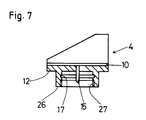
- FIG. 7 shows a further exemplary embodiment of a wear indicator body which, in addition to the radially circumferential recess 17, is provided with an internal thread 27 for receiving a threaded plug, starting from the extension end 25.
- the diameter of the circumferential recess 17 is larger than the thread diameter.
- the thread serves to fasten a threaded plug, which can be used as an alternative to the protective plug 19, in order to protect the inner region of the wear indicator body extension 13 from damage and contamination and to fix the wear indicator 4 at least until after the friction lining has been applied in the through opening 14 of the carrier plate 2.
- the threaded plug is mounted with the wear indicator 4 before the friction lining 3 is connected to the carrier plate 2.
- the screwing and unscrewing process can be automated with simple means.
- the threaded plug has a slot, cross-slot or hexagon recess on the end facing away from the thread in order to accommodate appropriate mounting tools.
Landscapes
- Engineering & Computer Science (AREA)
- General Engineering & Computer Science (AREA)
- Mechanical Engineering (AREA)
- Braking Arrangements (AREA)
Applications Claiming Priority (2)
| Application Number | Priority Date | Filing Date | Title |
|---|---|---|---|
| DE19526607A DE19526607A1 (de) | 1995-07-21 | 1995-07-21 | Bremsbackenanordnung für Scheibenbremsen sowie Verfahren zu deren Herstellung |
| DE19526607 | 1995-07-21 |
Publications (2)
| Publication Number | Publication Date |
|---|---|
| EP0754875A1 true EP0754875A1 (fr) | 1997-01-22 |
| EP0754875B1 EP0754875B1 (fr) | 2000-05-10 |
Family
ID=7767391
Family Applications (1)
| Application Number | Title | Priority Date | Filing Date |
|---|---|---|---|
| EP95120219A Expired - Lifetime EP0754875B1 (fr) | 1995-07-21 | 1995-12-20 | Dispositif de garniture pour frein à disque ainsi que procédé pour son obtention |
Country Status (2)
| Country | Link |
|---|---|
| EP (1) | EP0754875B1 (fr) |
| DE (2) | DE19526607A1 (fr) |
Cited By (8)
| Publication number | Priority date | Publication date | Assignee | Title |
|---|---|---|---|---|
| EP0781936B1 (fr) * | 1995-12-27 | 2001-03-21 | Compagnie Plastic Omnium | Témoin d'usure de garniture de friction, notamment de plaquette de frein |
| GB2361542A (en) * | 2000-04-19 | 2001-10-24 | Federal Mogul Technology Ltd | Sensor for measuring wear in brakes |
| EP1496283A1 (fr) * | 2003-07-11 | 2005-01-12 | BPW Bergische Achsen KG | Dispositif de détéction d'usure pour garniture de frein. |
| DE102008032818A1 (de) | 2007-10-10 | 2009-04-16 | Continental Teves Ag & Co. Ohg | Bremsbacke |
| CN106068397A (zh) * | 2014-09-08 | 2016-11-02 | 泰明顿服务责任有限公司 | 带有磨损指示器的制动蹄 |
| US10167916B2 (en) | 2016-07-29 | 2019-01-01 | Trw Automotive U.S. Llc | Brake pad wear sensor |
| CN112253659A (zh) * | 2020-10-14 | 2021-01-22 | 何建斌 | 一种制动器用直观式刹车片磨损警示设备 |
| CN113202887A (zh) * | 2021-05-21 | 2021-08-03 | 深圳市太美亚电子科技有限公司 | 一种新能源汽车制动装置 |
Families Citing this family (1)
| Publication number | Priority date | Publication date | Assignee | Title |
|---|---|---|---|---|
| DE10346486B4 (de) * | 2003-10-02 | 2012-08-02 | Murrplastik Systemtechnik Gmbh | Energieführungskette |
Citations (5)
| Publication number | Priority date | Publication date | Assignee | Title |
|---|---|---|---|---|
| GB1264573A (fr) * | 1970-04-13 | 1972-02-23 | ||
| US4298857A (en) * | 1980-02-01 | 1981-11-03 | Ford Motor Company | Brake wear indicator system |
| US4685540A (en) * | 1984-06-05 | 1987-08-11 | Lucas Industries Public Limited Company | Signal transmitter for monitoring a brake lining |
| EP0546759A1 (fr) * | 1991-12-12 | 1993-06-16 | Sumitomo Wiring Systems, Ltd. | Détecteur d'usage de matériaux de garniture de freinage |
| US5250588A (en) * | 1990-01-16 | 1993-10-05 | Ceram Sna Inc. | Organic friction material composition for use to produce friction linings |
-
1995
- 1995-07-21 DE DE19526607A patent/DE19526607A1/de not_active Withdrawn
- 1995-12-20 DE DE59508324T patent/DE59508324D1/de not_active Expired - Fee Related
- 1995-12-20 EP EP95120219A patent/EP0754875B1/fr not_active Expired - Lifetime
Patent Citations (5)
| Publication number | Priority date | Publication date | Assignee | Title |
|---|---|---|---|---|
| GB1264573A (fr) * | 1970-04-13 | 1972-02-23 | ||
| US4298857A (en) * | 1980-02-01 | 1981-11-03 | Ford Motor Company | Brake wear indicator system |
| US4685540A (en) * | 1984-06-05 | 1987-08-11 | Lucas Industries Public Limited Company | Signal transmitter for monitoring a brake lining |
| US5250588A (en) * | 1990-01-16 | 1993-10-05 | Ceram Sna Inc. | Organic friction material composition for use to produce friction linings |
| EP0546759A1 (fr) * | 1991-12-12 | 1993-06-16 | Sumitomo Wiring Systems, Ltd. | Détecteur d'usage de matériaux de garniture de freinage |
Cited By (12)
| Publication number | Priority date | Publication date | Assignee | Title |
|---|---|---|---|---|
| EP0781936B1 (fr) * | 1995-12-27 | 2001-03-21 | Compagnie Plastic Omnium | Témoin d'usure de garniture de friction, notamment de plaquette de frein |
| GB2361542A (en) * | 2000-04-19 | 2001-10-24 | Federal Mogul Technology Ltd | Sensor for measuring wear in brakes |
| EP1496283A1 (fr) * | 2003-07-11 | 2005-01-12 | BPW Bergische Achsen KG | Dispositif de détéction d'usure pour garniture de frein. |
| DE102008032818A1 (de) | 2007-10-10 | 2009-04-16 | Continental Teves Ag & Co. Ohg | Bremsbacke |
| CN106068397A (zh) * | 2014-09-08 | 2016-11-02 | 泰明顿服务责任有限公司 | 带有磨损指示器的制动蹄 |
| US20170184169A1 (en) * | 2014-09-08 | 2017-06-29 | Tmd Friction Services Gmbh | Brake shoe having a wear indicator |
| US10385938B2 (en) | 2014-09-08 | 2019-08-20 | Tmd Friction Services Gmbh | Brake shoe having a wear indicator |
| CN106068397B (zh) * | 2014-09-08 | 2019-11-22 | 泰明顿服务责任有限公司 | 带有磨损指示器的制动蹄 |
| US10167916B2 (en) | 2016-07-29 | 2019-01-01 | Trw Automotive U.S. Llc | Brake pad wear sensor |
| CN112253659A (zh) * | 2020-10-14 | 2021-01-22 | 何建斌 | 一种制动器用直观式刹车片磨损警示设备 |
| CN113202887A (zh) * | 2021-05-21 | 2021-08-03 | 深圳市太美亚电子科技有限公司 | 一种新能源汽车制动装置 |
| CN113202887B (zh) * | 2021-05-21 | 2022-09-13 | 深圳市太美亚电子科技有限公司 | 一种新能源汽车制动装置 |
Also Published As
| Publication number | Publication date |
|---|---|
| EP0754875B1 (fr) | 2000-05-10 |
| DE59508324D1 (de) | 2000-06-15 |
| DE19526607A1 (de) | 1997-01-23 |
Similar Documents
| Publication | Publication Date | Title |
|---|---|---|
| DE3128939C2 (fr) | ||
| EP0754875B1 (fr) | Dispositif de garniture pour frein à disque ainsi que procédé pour son obtention | |
| EP0465954B1 (fr) | Détecteur d'usage de garniture de freinage | |
| EP0411284B1 (fr) | Indicateur d'usure pour indiquer la limite d'usure des garnitures de frein de véhicules automobiles et analogue | |
| EP1471341A1 (fr) | Fixation d'un capteur à petite construction sur un réservoir au moyen d'une vis de pression concentrique | |
| DE19954354A1 (de) | Anschlußvorrichtung mit Kappe | |
| WO2012110160A1 (fr) | Capteur de vibrations et procédé de fabrication d'un tel capteur de vibrations | |
| DE3204305C1 (de) | Bremsbelagverschleiß-Überwachungsorgan | |
| DE10355513B4 (de) | Distanzscheibe, die zum Gebrauch mit einer Bremsscheibe einschliesslich eines Sattels geeignet ist | |
| EP3899550B1 (fr) | Capteur de vitesse inductif et procédé pour le fabriquer | |
| DE1928991B2 (de) | Bremsbackenhalterung für Scheibenbremsen | |
| DE3233634A1 (de) | Bremsbacke mit fuehler fuer eine verschleissanzeigeeinrichtung | |
| DE19825300C2 (de) | Wärmeisolierter Bremsbelag-Verschleißanzeiger | |
| DE102005052309A1 (de) | Anschlußbolzen, Anschlußelement und elektrisch leitende Kupplungsvorrichtung | |
| DE102009050564B4 (de) | Befestigung für Elektromagneten | |
| DE8807884U1 (de) | Geber für den Betriebszustand von Bremsen | |
| DE102005014185A1 (de) | Befestigungsvorrichtung | |
| DE102006028577B4 (de) | Mutter mit einem Mutternkörper und einer auf dem Mutternkörper gehaltenen Kappe | |
| DE102018121850A1 (de) | Steckerschutzvorrichtung und Sensoranordnung mit einer solchen Steckerschutzvorrichtung | |
| DE19926000B4 (de) | Befestigungsvorrichtung für einen Bremssattel an einem Radträger | |
| DE3640888A1 (de) | Ueberwachungsvorrichtung fuer den belagverschleiss in backenbremsen | |
| DE8128633U1 (de) | Bremsbacke mit fuehler fuer eine verschleissanzeigeeinrichtung | |
| DE19525801C2 (de) | Vorrichtung zum elektrisch leitenden Verbinden von zwei elektrischen Leitungen | |
| EP1158199B1 (fr) | Dispositif d'indication d'usure pour garnitures de freins à disque | |
| EP1948955B1 (fr) | Procede de montage d'un indicateur d'usure sur un frein |
Legal Events
| Date | Code | Title | Description |
|---|---|---|---|
| PUAI | Public reference made under article 153(3) epc to a published international application that has entered the european phase |
Free format text: ORIGINAL CODE: 0009012 |
|
| 17P | Request for examination filed |
Effective date: 19951220 |
|
| AK | Designated contracting states |
Kind code of ref document: A1 Designated state(s): DE ES FR GB IT SE |
|
| 17Q | First examination report despatched |
Effective date: 19990122 |
|
| GRAG | Despatch of communication of intention to grant |
Free format text: ORIGINAL CODE: EPIDOS AGRA |
|
| GRAG | Despatch of communication of intention to grant |
Free format text: ORIGINAL CODE: EPIDOS AGRA |
|
| GRAH | Despatch of communication of intention to grant a patent |
Free format text: ORIGINAL CODE: EPIDOS IGRA |
|
| RAP1 | Party data changed (applicant data changed or rights of an application transferred) |
Owner name: BBA FRICTION GMBH |
|
| GRAH | Despatch of communication of intention to grant a patent |
Free format text: ORIGINAL CODE: EPIDOS IGRA |
|
| GRAA | (expected) grant |
Free format text: ORIGINAL CODE: 0009210 |
|
| AK | Designated contracting states |
Kind code of ref document: B1 Designated state(s): DE ES FR GB IT SE |
|
| PG25 | Lapsed in a contracting state [announced via postgrant information from national office to epo] |
Ref country code: IT Free format text: LAPSE BECAUSE OF FAILURE TO SUBMIT A TRANSLATION OF THE DESCRIPTION OR TO PAY THE FEE WITHIN THE PRESCRIBED TIME-LIMIT;WARNING: LAPSES OF ITALIAN PATENTS WITH EFFECTIVE DATE BEFORE 2007 MAY HAVE OCCURRED AT ANY TIME BEFORE 2007. THE CORRECT EFFECTIVE DATE MAY BE DIFFERENT FROM THE ONE RECORDED. Effective date: 20000510 Ref country code: GB Free format text: LAPSE BECAUSE OF FAILURE TO SUBMIT A TRANSLATION OF THE DESCRIPTION OR TO PAY THE FEE WITHIN THE PRESCRIBED TIME-LIMIT Effective date: 20000510 Ref country code: FR Free format text: LAPSE BECAUSE OF FAILURE TO SUBMIT A TRANSLATION OF THE DESCRIPTION OR TO PAY THE FEE WITHIN THE PRESCRIBED TIME-LIMIT Effective date: 20000510 Ref country code: ES Free format text: THE PATENT HAS BEEN ANNULLED BY A DECISION OF A NATIONAL AUTHORITY Effective date: 20000510 |
|
| REF | Corresponds to: |
Ref document number: 59508324 Country of ref document: DE Date of ref document: 20000615 |
|
| PG25 | Lapsed in a contracting state [announced via postgrant information from national office to epo] |
Ref country code: SE Free format text: LAPSE BECAUSE OF FAILURE TO SUBMIT A TRANSLATION OF THE DESCRIPTION OR TO PAY THE FEE WITHIN THE PRESCRIBED TIME-LIMIT Effective date: 20000810 |
|
| EN | Fr: translation not filed | ||
| GBV | Gb: ep patent (uk) treated as always having been void in accordance with gb section 77(7)/1977 [no translation filed] |
Effective date: 20000510 |
|
| PLBE | No opposition filed within time limit |
Free format text: ORIGINAL CODE: 0009261 |
|
| STAA | Information on the status of an ep patent application or granted ep patent |
Free format text: STATUS: NO OPPOSITION FILED WITHIN TIME LIMIT |
|
| 26N | No opposition filed | ||
| PGFP | Annual fee paid to national office [announced via postgrant information from national office to epo] |
Ref country code: DE Payment date: 20081231 Year of fee payment: 14 |
|
| PG25 | Lapsed in a contracting state [announced via postgrant information from national office to epo] |
Ref country code: DE Free format text: LAPSE BECAUSE OF NON-PAYMENT OF DUE FEES Effective date: 20100701 |