EP0754296B1 - Molten metal immersion probe - Google Patents
Molten metal immersion probe Download PDFInfo
- Publication number
- EP0754296B1 EP0754296B1 EP96904241A EP96904241A EP0754296B1 EP 0754296 B1 EP0754296 B1 EP 0754296B1 EP 96904241 A EP96904241 A EP 96904241A EP 96904241 A EP96904241 A EP 96904241A EP 0754296 B1 EP0754296 B1 EP 0754296B1
- Authority
- EP
- European Patent Office
- Prior art keywords
- probe
- molten metal
- sample chamber
- face
- immersion
- Prior art date
- Legal status (The legal status is an assumption and is not a legal conclusion. Google has not performed a legal analysis and makes no representation as to the accuracy of the status listed.)
- Expired - Lifetime
Links
- 239000000523 sample Substances 0.000 title claims description 183
- 229910052751 metal Inorganic materials 0.000 title claims description 135
- 239000002184 metal Substances 0.000 title claims description 135
- 238000007654 immersion Methods 0.000 title claims description 38
- 238000007711 solidification Methods 0.000 claims description 26
- 230000008023 solidification Effects 0.000 claims description 26
- 238000000034 method Methods 0.000 claims description 12
- 239000000463 material Substances 0.000 claims description 11
- 239000004568 cement Substances 0.000 claims description 7
- 239000000945 filler Substances 0.000 claims description 2
- 238000007789 sealing Methods 0.000 claims 1
- 238000005070 sampling Methods 0.000 description 15
- 239000002893 slag Substances 0.000 description 8
- 238000004458 analytical method Methods 0.000 description 4
- 239000007789 gas Substances 0.000 description 4
- 239000000123 paper Substances 0.000 description 3
- 239000011819 refractory material Substances 0.000 description 3
- 239000007767 bonding agent Substances 0.000 description 2
- 239000000919 ceramic Substances 0.000 description 2
- 239000003795 chemical substances by application Substances 0.000 description 2
- 238000007710 freezing Methods 0.000 description 2
- 230000008014 freezing Effects 0.000 description 2
- 238000005259 measurement Methods 0.000 description 2
- BASFCYQUMIYNBI-UHFFFAOYSA-N platinum Chemical compound [Pt] BASFCYQUMIYNBI-UHFFFAOYSA-N 0.000 description 2
- 239000010453 quartz Substances 0.000 description 2
- 239000011347 resin Substances 0.000 description 2
- 229920005989 resin Polymers 0.000 description 2
- 239000004576 sand Substances 0.000 description 2
- VYPSYNLAJGMNEJ-UHFFFAOYSA-N silicon dioxide Inorganic materials O=[Si]=O VYPSYNLAJGMNEJ-UHFFFAOYSA-N 0.000 description 2
- 239000000126 substance Substances 0.000 description 2
- 238000012546 transfer Methods 0.000 description 2
- RYGMFSIKBFXOCR-UHFFFAOYSA-N Copper Chemical compound [Cu] RYGMFSIKBFXOCR-UHFFFAOYSA-N 0.000 description 1
- 229910002651 NO3 Inorganic materials 0.000 description 1
- NHNBFGGVMKEFGY-UHFFFAOYSA-N Nitrate Chemical compound [O-][N+]([O-])=O NHNBFGGVMKEFGY-UHFFFAOYSA-N 0.000 description 1
- 229910000831 Steel Inorganic materials 0.000 description 1
- 239000000853 adhesive Substances 0.000 description 1
- 229910052782 aluminium Inorganic materials 0.000 description 1
- XAGFODPZIPBFFR-UHFFFAOYSA-N aluminium Chemical group [Al] XAGFODPZIPBFFR-UHFFFAOYSA-N 0.000 description 1
- PNEYBMLMFCGWSK-UHFFFAOYSA-N aluminium oxide Inorganic materials [O-2].[O-2].[O-2].[Al+3].[Al+3] PNEYBMLMFCGWSK-UHFFFAOYSA-N 0.000 description 1
- 230000015572 biosynthetic process Effects 0.000 description 1
- 238000001816 cooling Methods 0.000 description 1
- 229910052802 copper Inorganic materials 0.000 description 1
- 239000010949 copper Substances 0.000 description 1
- 238000013211 curve analysis Methods 0.000 description 1
- 230000001419 dependent effect Effects 0.000 description 1
- 230000000694 effects Effects 0.000 description 1
- 238000010438 heat treatment Methods 0.000 description 1
- 230000008676 import Effects 0.000 description 1
- 238000009413 insulation Methods 0.000 description 1
- 230000013011 mating Effects 0.000 description 1
- 239000007769 metal material Substances 0.000 description 1
- 238000012986 modification Methods 0.000 description 1
- 230000004048 modification Effects 0.000 description 1
- 239000012811 non-conductive material Substances 0.000 description 1
- 239000004033 plastic Substances 0.000 description 1
- 229910052697 platinum Inorganic materials 0.000 description 1
- PXXKQOPKNFECSZ-UHFFFAOYSA-N platinum rhodium Chemical compound [Rh].[Pt] PXXKQOPKNFECSZ-UHFFFAOYSA-N 0.000 description 1
- 238000002360 preparation method Methods 0.000 description 1
- 238000012545 processing Methods 0.000 description 1
- 239000010959 steel Substances 0.000 description 1
- 238000002076 thermal analysis method Methods 0.000 description 1
- 239000011800 void material Substances 0.000 description 1
Images

Classifications
-
- G—PHYSICS
- G01—MEASURING; TESTING
- G01N—INVESTIGATING OR ANALYSING MATERIALS BY DETERMINING THEIR CHEMICAL OR PHYSICAL PROPERTIES
- G01N1/00—Sampling; Preparing specimens for investigation
- G01N1/02—Devices for withdrawing samples
- G01N1/10—Devices for withdrawing samples in the liquid or fluent state
- G01N1/12—Dippers; Dredgers
- G01N1/125—Dippers; Dredgers adapted for sampling molten metals
-
- Y—GENERAL TAGGING OF NEW TECHNOLOGICAL DEVELOPMENTS; GENERAL TAGGING OF CROSS-SECTIONAL TECHNOLOGIES SPANNING OVER SEVERAL SECTIONS OF THE IPC; TECHNICAL SUBJECTS COVERED BY FORMER USPC CROSS-REFERENCE ART COLLECTIONS [XRACs] AND DIGESTS
- Y10—TECHNICAL SUBJECTS COVERED BY FORMER USPC
- Y10S—TECHNICAL SUBJECTS COVERED BY FORMER USPC CROSS-REFERENCE ART COLLECTIONS [XRACs] AND DIGESTS
- Y10S73/00—Measuring and testing
- Y10S73/09—Molten metal samplers
Definitions
- the present invention relates generally to immersion sensors for use in molten metal processing vessels which can obtain the liquidus temperature of the molten metal during solidification. More particularly, the present invention relates to a molten metal immersion probe that obtains a molten metal sample and that solidifies the sample in a particular manner to more reliably measure liquidus temperature information.
- a common sampling technique for determining the chemical analysis of molten metal as disclosed in US 4,361,053 utilizes a measurement of the temperature at which the molten metal solidifies. Accordingly, a sampling device having an internal cavity and a temperature sensing element positioned within the cavity is immersed into a bath of the molten metal, the molten metal enters the cavity through an inlet, and the cavity fills under the force of ferrostatic pressure. In typical prior art sampling devices, the molten metal sample solidifies along a solidification front that progresses from the walls of the cavity toward the thermal and geometric center of the cavity.
- Another problem with a typical prior art sampling device is that the reliability of the device is dependent upon the ability of the internal cavity to fill completely when the device is immersed within the molten metal bath and to remain filled when the device is withdrawn from the molten metal bath. As may be understood, void formation near the temperature sensing element can also occur when a portion of the molten metal sample within the cavity escapes and/or when the cavity does not completely fill with the molten metal.
- an immersion probe for collecting a sample of the molten metal and for determining a liquidus temperature of the metal during solidification.
- the probe is generally longitudinally shaped and is immersed in the molten metal in an immersion direction, with a first longitudinal end of the probe initially contacting the molten metal.
- the probe has a first refractory body with an immersion face facing toward the first end of the probe, an interior sample chamber, and a passageway extending between the immersion face and the sample chamber.
- the interior walls of the sample chamber sink thermal energy from within the sample chamber at a first rate R 1 .
- a heat sink is positioned within the sample chamber adjacent a first end wall proximate the immersion face, and the heat sink has an aperture through which molten metal passes from the passageway into the sample chamber.
- An insulating shield is positioned within the sample chamber adjacent the heat sink such that the heat sink is insulated from thermal energy within the sample chamber, and the insulating shield has an aperture through which the molten metal flows after the molten metal passes through the heat sink aperture.
- the insulating shield sinks thermal energy from adjacent molten metal at a second rate R 2 slower than the first rateR 1 .
- a liquidus temperature sensor is positioned within the sample chamber away from the insulating shield.
- the probe is immersed in the molten metal and the molten metal flows into the sample chamber through the passageway until the sample chamber is substantially filled.
- the heat sink sinks thermal energy from and solidifies adjacent molten metal.
- the solidified molten metal seals the sample within the sample chamber, and the sealed sample solidifies along a solidification front that progresses toward the insulating shield. With the solidification front directed as such, gaseous voids are prevented from being formed adjacent the liquidus temperature sensor, and the liquidus temperature of the molten metal during solidification is determined from the solidifying sample with the liquidus temperature sensor.
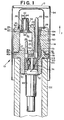
- a molten metal immersion probe 10 for collecting a sample of a molten metal and for determining a liquidus temperature of the metal during solidification, in accordance with the present invention.
- the probe 10 is generally longitudinally shaped and is immersed in the molten metal (not shown) in an immersion direction I. As such, the probe 10 initially contacts the molten metal at a first longitudinal end 12.
- the probe 10 has first and second generally porous refractory bodies 14, 16 bonded together at respective first and second abutting faces 18, 20, and is positioned at one end of a consumable cardboard tube 22.
- the tube 22 may be interference fitted to the probe 10 at the second body 16, as seen in Fig. 1, and an adhesive agent 23 may also be employed to secure the tube 22 to the second body 16.
- the first body 14 has an immersion face 24 facing generally toward the first end 12 of the probe 10 and generally opposite the first abutting face 18.
- an interior sample chamber 26 defined by a plurality of interior walls 27 including a first end wall 28 proximate to and generally parallel with respect to the immersion face 24.
- the material surrounding the sample chamber 26 and forming the interior walls 27 sinks thermal energy from within the sample chamber 26 at a first rate R 1 and solidifies a molten metal sample (not shown) in the sample chamber 26 at a desired rate for thermal analysis.
- the size and geometry of the sample chamber 26 allow the collection of a large enough molten metal sample for a proper liquidus temperature determination.
- one of the interior walls 27 of the sample chamber 26 has a large, flat surface area to produce a like flat surface area an the solidified molten metal sample. As may be realized, such a flat surface area aids in the preparation of the solidified sample for spectrometer analysis.
- the first and second bodies 14, 16 are constructed from a porous refractory material, such as baked resin sand, to allow air to ventilate from the sample chamber 26 when the chamber 26 is filled with the molten metal sample.
- a porous refractory material such as baked resin sand
- the material surrounding the sample chamber 26 is thick enough to provide the necessary mechanical strength and to thermally shield or insulate the solidifying sample within the sample chamber 26 from thermal energy from the molten metal bath (not shown).
- the first body 14 has a passageway 30 extending between an opening 32 in the immersion face 24 and a portal 34 in the first end wall 28, and, in the present embodiment, an inlet tube 36 extends through the passageway 30 and past the immersion face 24 generally in the immersion direction I to an external end 38.
- the inlet tube 36 is constructed from quartz and is fixed in place with a refractory cement 40.
- the inlet tube 36 may also be constructed from another material such as ceramic or metal and may be fixed in place with other fixing agents.
- the tube 36 may be eliminated such that molten metal flows directly through the passageway 30.
- a deoxidizing liner 42 that extends along at least a portion of the inlet tube 36 and preferably along the entire length of the tube 36.
- the deoxidizing liner 42 deoxidizes the sample of molten metal as it enters the sample chamber 26 through the inlet tube 36.
- the deoxidizing liner is an aluminum liner, although one skilled in the art will recognize that other deoxidizing materials and geometries (i.e. wires, meshes, strips, etc.) may be employed.
- the probe 10, in the present embodiment, has a first metal cap 44 covering the external end 38 of the inlet tube 36 to prevent materials from prematurely entering the sample chamber 26.
- the first cap 44 is constructed of a metal material that dissolves upon contact with the molten metal for a predetermined time period. If desired, the first metal cap 44 may be eliminated for some applications.
- a heat sink 46 having an aperture 48 corresponding in size with and generally aligned with the portal 34 in the first end wall 28 through which the molten metal passes from the inlet tube 36 and into the sample chamber 26.
- the heat sink 46 is a circular steel washer.
- a high heat capacity metal such as copper or ceramic such as alumina nitrate may be employed.
- the shield 50 has an aperture 52 corresponding in size with and generally aligned with the aperture 48 in the heat sink 46 and the portal 34 in the first end wall 28.
- the insulating shield 50 sinks thermal energy from within the sample chamber 26 at a second rate R 2 which is slower than the first rate R 1 of the interior walls 27.
- the insulating shield 50 be constructed from a highly insulating fibrous refractory material.
- the insulating shield 50 is press fit within the sample chamber 26 and secures the heat sink 46 in place.
- the mass of molten metal within the sample chamber 26 is thermally separated from the heat sink 46.
- the heat sink 46 is thereby protected from thermal energy from molten metal within the sample chamber 26. Accordingly, the heat sink 46 can only absorb thermal energy from molten metal at and about the aperture 48 extending therethrough.
- the thermal center of the sample chamber 26 is moved away from the geometric center of the sample chamber 26 and toward the immersion face 24 of the first body 14, and the molten metal sample sealed within the sample chamber 26 solidifies along a solidification front that progresses toward the insulating shield 50. Accordingly, the last metal to begin freezing and the metal most likely to have gaseous voids is formed adjacent the insulating shield 50.
- the probe 10 has a liquidus temperature sensing device 54 that extends through an opening in the first abutting face 18 of the first body 14 and into the sample chamber 26 to a sensor 56 at a sensing end.
- the sensor 56 is positioned within the sample chamber 26 away from the , insulating shield 50 and thus away from the thermal center of the sample chamber 26. Accordingly, gaseous voids are prevented from being formed adjacent the sensor 56, the sensor 56 is positioned at or about the geometric center of the sample chamber 26.
- the probe 10 is employed to concurrently determine a bath temperature of the molten metal and the liquidus temperature of the molten metal during solidification. Consequently, the first body 14 has a generally longitudinal channel 58 extending between the immersion face 24 and the first abutting face 18, and a bath temperature sensing device 60 extends through the longitudinal channel 58 and past the immersion face 24 to a bath sensor 62 at a sensing end. Preferably, the remaining space in the longitudinal channel 58 is filled with an insulating filler material 64 to secure the bath temperature sensing device 60 to the first body 14.
- the material 64 is preferably a refractory material such as resin-coated sand or refractory cement, although one skilled in the art will recognize that other similar materials may employed. As should be understood, the material 64 provides the necessary insulation from the thermal energy released from the solidifying molten metal sample in the sample chamber 26, as well as from the surrounding molten metal bath.
- the first body 14 also has a second metal cap 66 positioned at the first longitudinal end 12 of the probe 10 to protect the first cap 44 and the sensor 62 of the bath temperature sensing device 60 prior to and during immersing of the probe 10 within the molten metal bath.
- the immersion face 24 of the first body 14 have a groove 68 into which the edge of the second cap 66 is mounted.
- the second cap 66 may be secured in the groove 68 by a bonding cement or other securing agents which should be apparent to one skilled in the art.
- the second metal cap 66 dissolves upon contact with the molten metal for a predetermined time period and the sensor 62 of the bath temperature sensing device 60 and the first metal cap 44 become exposed to the molten metal in the bath.
- the second refractory body 16 is fitted to the first refractory body 14 by way of the respective first and second abutting faces 18, 20 such that a portion of the second abutting face 20 forms one of the interior walls 27 of the sample chamber 26.
- the second body 16 has a connector face 70 generally opposite the second abutting face 20, and an electrical connector 69 extends into the second body 16 from the connector face 70.
- the electrical connector 69 supports the liquidus temperature sensing device 54 and the bath temperature sensing device 60, and the sensing devices 54, 60 are electrically connected to and extend from the electrical connector 69 to the respective sensors 56, 62.
- the electrical connector 69 is constructed from a non-conductive material such as plastic, and is press fit into the second body 16 at an aperture 72 in the connector face 70.
- the second body 16 has openings 73 at the second abutting face 20 through which the sensing devices 54, 60 extend, and the second body 16 is shaped to allow only one possible orientation for mounting the electrical connector 69 and the sensing devices 54, 60 to the second body 16.
- a refractory cement 74 is employed to secure the electrical connector 69 and the sensing devices 54, 60 to the second body 16.
- the first and second abutting faces 18 and 20 of the respective first and second bodies 14, 16 each have a radial step configuration 76 such that the first abutting face 18 is Complementarily received by the second abutting face 20.
- the bonding surface area between the first and second bodies 14, 16 is maximized to assure a strong bond by way of a bonding agent 78.
- the bonding agent 78 is a refractory cement, although one skilled in the art will recognize that other bonding materials may be employed.
- the first and second abutting faces 18, 20 preferably also have a tongue and groove arrangement 80 to prevent the first and second bodies 14, 16 from rotating with respective to each other.
- the tongue 80a extends from the first body 14 and is received by a groove 80b in the second body 16.
- the respective positions of the tongue and groove 80, 82 may be reversed or other means for preventing rotation of the first and second bodies 14, 16 may be employed.
- both sensing devices 54, 60 are thermocouples having noble bi-metal thermoelements such as platinum / platinum-rhodium (not shown).
- noble bi-metal thermoelements such as platinum / platinum-rhodium (not shown).
- thermoelements and thermocouples may be employed.
- the sensors 56, 62 of the respective thermocouples 54, 60 are protected with thin wall quartz tubes 84a, 84b, as is well known in the expendable thermocouple art, and conductive wires 86a, 86b, 88a, 88b respectively extend from the sensors 56, 62 to the electrical connector 69.
- the wires 86a, 86b, 88a, 88b are connected to the electrical connector 69 at compensated junctions 90a, 90b, 90c.
- wire 86a is connected to junction 90a
- wires 86b and 88b are connected to junction 90b
- wire 88a is connected to junction 90c.
- the compensated junctions 90a, 90b, 90c are located at the same general longitudinal position within the refractory cement 74 of the second body 16. Accordingly, the compensated junctions 90a, 90b, 90c are in thermal equilibrium and unwanted thermoelectric forces are prevented.
- the compensated junctions 90a, 90b, 90c are respectively electrically connected to compensated contacts 92a, 92b, 92c and a temperature recording device (not shown) is electrically connected to the probe 10 at the contacts 92a, 92b, 92c when the probe 10 is in use.
- a molten metal bath typically has a slag layer (not shown) at the uppermost region of the bath where the molten metal is exposed to air and is partially solidified. Accordingly, once all the aforementioned elements are assembled to form the probe 10, it is preferable that a paper cap 94 (as seen in Fig. 1) be placed over the probe 10 to protect the probe 10 and especially the first end 12 of the probe 10 when initially inserted through the slag layer during immersion. The paper cap 94 is consumed during the transit through the slag layer, but slag is prevented from freezing to the second metal cap 66 during passage of the probe 10 to the molten metal below the slag layer.
- the probe 10 is suspended by the cardboard tube 22 from a metal pole (not shown) that has a non-directional mating end in electrical contact with the electrical connector 69.
- the probe 10 is then immersed into a molten metal bath, through the slag layer atop the molten metal, and into the molten metal itself.
- the paper cap 94 is consumed while the probe 10 crosses the slag layer, but the second metal cap 66, the bath sensor.62 and the inlet tube 36 are protected from the slag.
- the molten metal contacts and dissolves the second cap 66, exposing the first cap 44 and the bath temperature sensing device 60 to the molten metal. Accordingly, the bath sensor 62 begins to determine the bath temperature of the molten metal almost instantly, and the molten metal contacts and dissolves the first cap 44 to open the inlet tube 36. As a result, a sample of the molten metal flows into the sample chamber 26 through the inlet tube 36 under ferrostatic pressure until the sample chamber 26 is filled. While the sample of the molten metal is flowing through the inlet tube 36, the sample is deoxidized by the deoxidizing liner 42. As should be understood, air in the sample chamber 26 is evacuated during the filling operation through the porous first and second refractory bodies 14, 16.
- the flow through the inlet tube 36 ceases, and the heat sink 46 sinks thermal energy from a portion of the molten metal adjacent the aperture 48 of the heat sink 46 to solidify the portion. Accordingly, the solidified portion of the metal proximate the heat sink 46 seals the molten metal sample within the sample chamber 26, and the liquidus sensor 56 located within the sample chamber 26 begins to determine the temperature of the molten metal sealed within the sample chamber 36.
- the thermal center of the sample chamber 26 is moved away from the liquidus sensor 56, the sealed sample solidifies along a solidification front that progresses toward the insulating shield 50, and gaseous voids are prevented from being formed adjacent the liquidus sensor 56 during solidification.
- the latent heat released during solidification balances the heat removal through the interior walls 27 of the sample chamber 26 and a characteristic liquidus arrest temperature may be measured with the liquidus sensor 56. Accordingly, with the temperature readings provided by the liquidus sensor 56 during solidification, a cooling curve analysis during solidification may be performed to determine a chemical analysis of the molten metal. Thereafter, the probe 10 may be removed from the molten metal bath and the solidified sample within the sample chamber 26 may be removed for further analysis.
- the present invention comprises a new and useful molten metal immersion sensor that prevents gaseous voids from being formed in a sample chamber 26 adjacent the liquidus sensor 56, that insures that the sample chamber 26 fills completely and remains filled, even during removal from the molten metal bath and that prevents non-uniform heating of the compensated connections for the liquidus and bath sensing devices 54, 60.
Landscapes
- Life Sciences & Earth Sciences (AREA)
- Biochemistry (AREA)
- Physics & Mathematics (AREA)
- Health & Medical Sciences (AREA)
- Chemical & Material Sciences (AREA)
- Analytical Chemistry (AREA)
- Hydrology & Water Resources (AREA)
- General Health & Medical Sciences (AREA)
- General Physics & Mathematics (AREA)
- Immunology (AREA)
- Pathology (AREA)
- Investigating And Analyzing Materials By Characteristic Methods (AREA)
- Investigating Or Analyzing Materials Using Thermal Means (AREA)
- Waste-Gas Treatment And Other Accessory Devices For Furnaces (AREA)
Applications Claiming Priority (3)
| Application Number | Priority Date | Filing Date | Title |
|---|---|---|---|
| US384985 | 1995-02-06 | ||
| US08/384,985 US5577841A (en) | 1995-02-06 | 1995-02-06 | Molten metal immersion probe |
| PCT/IB1996/000235 WO1996024829A1 (en) | 1995-02-06 | 1996-01-29 | Molten metal immersion probe |
Publications (2)
| Publication Number | Publication Date |
|---|---|
| EP0754296A1 EP0754296A1 (en) | 1997-01-22 |
| EP0754296B1 true EP0754296B1 (en) | 2003-05-02 |
Family
ID=23519565
Family Applications (1)
| Application Number | Title | Priority Date | Filing Date |
|---|---|---|---|
| EP96904241A Expired - Lifetime EP0754296B1 (en) | 1995-02-06 | 1996-01-29 | Molten metal immersion probe |
Country Status (16)
| Country | Link |
|---|---|
| US (1) | US5577841A (pl) |
| EP (1) | EP0754296B1 (pl) |
| KR (1) | KR100390598B1 (pl) |
| CN (1) | CN1100255C (pl) |
| AU (1) | AU690823B2 (pl) |
| BR (1) | BR9605113A (pl) |
| CA (1) | CA2187187A1 (pl) |
| DE (1) | DE69627764T2 (pl) |
| ES (1) | ES2194976T3 (pl) |
| PL (1) | PL179795B1 (pl) |
| RU (1) | RU2155948C2 (pl) |
| TR (1) | TR199600800T1 (pl) |
| TW (1) | TW360568B (pl) |
| UA (1) | UA48949C2 (pl) |
| WO (1) | WO1996024829A1 (pl) |
| ZA (1) | ZA96843B (pl) |
Families Citing this family (40)
| Publication number | Priority date | Publication date | Assignee | Title |
|---|---|---|---|---|
| SE508842C2 (sv) * | 1996-02-26 | 1998-11-09 | Sintercast Ab | Förfarande och anordning för mätning av temperaturen hos en smälta i ett provkärl jämte användning av optisk pyrometri |
| US6679627B1 (en) * | 1997-11-04 | 2004-01-20 | Rdc Controle Ltee | Self-floating device for measuring the temperature of liquids |
| JP4111356B2 (ja) * | 1998-01-20 | 2008-07-02 | 川惣電機工業株式会社 | 溶融金属プローブ |
| DE29909595U1 (de) * | 1999-06-01 | 1999-10-07 | Minkon Sampler-Technik GmbH, 40699 Erkrath | Vorrichtung zur Entnahme von Schlackenproben |
| US6220748B1 (en) | 1999-01-15 | 2001-04-24 | Alcoa Inc. | Method and apparatus for testing material utilizing differential temperature measurements |
| SE0104252D0 (sv) * | 2001-12-17 | 2001-12-17 | Sintercast Ab | New device |
| DE10331124B3 (de) * | 2003-07-09 | 2005-02-17 | Heraeus Electro-Nite International N.V. | Verfahren und Vorrichtung zum Messen der Abkühlkurve von Schmelzenproben und/oder der Aufheizkurve von Schmelzenproben sowie deren Verwendung |
| US6942381B2 (en) * | 2003-09-25 | 2005-09-13 | Alcoa Inc. | Molten cryolitic bath probe |
| DE10359449B3 (de) * | 2003-12-17 | 2005-03-03 | Heraeus Electro-Nite International N.V. | Trägerrohr für Sensoren |
| RU2273841C1 (ru) * | 2004-11-01 | 2006-04-10 | ООО "Компания "Нординкрафт" | Способ спектрального анализа элементов металлического расплава в плавильном резервуаре и устройство для его осуществления |
| RU2308695C2 (ru) * | 2005-10-13 | 2007-10-20 | ООО "Нординкрафт-Сенсор" | Измерительный зонд для погружения в расплав металла |
| DE102005060492B3 (de) * | 2005-12-15 | 2007-05-24 | Heraeus Electro-Nite International N.V. | Messsonde zur Messung in Metall- oder Schlackeschmelzen |
| DE102005060493B3 (de) * | 2005-12-15 | 2006-11-30 | Heraeus Electro-Nite International N.V. | Messsonde |
| DE102006047765B3 (de) * | 2006-10-06 | 2007-12-20 | Heraeus Electro-Nite International N.V. | Eintauchlanze für die Analyse von Schmelzen und Flüssigkeiten |
| RU2389009C2 (ru) * | 2008-06-05 | 2010-05-10 | ООО "Нординкрафт-Сенсор" | Устройство для получения и подготовки пробы для исследования электропроводного расплава |
| CN101907587A (zh) * | 2009-06-05 | 2010-12-08 | 贺利氏电子耐特国际股份公司 | 插入式探针 |
| DE202009011860U1 (de) * | 2009-09-02 | 2010-03-04 | Türk & Hillinger GmbH | Hochtemperaturstecker |
| RU2448199C1 (ru) * | 2010-08-13 | 2012-04-20 | Государственное образовательное учреждение высшего профессионального образования "Санкт-Петербургский государственный горный институт имени Г.В. Плеханова (технический университет)" | Устройство для отбора проб расплава в электролизере |
| KR101211999B1 (ko) * | 2010-09-29 | 2012-12-13 | 우진 일렉트로나이트(주) | 듀얼 샘플러 복합 프로브 |
| DE102011121183B4 (de) | 2011-05-18 | 2014-02-27 | Heraeus Electro-Nite International N.V. | Probennehmer für die Probennahme aus Schmelzen mit einem Schmelzpunkt größer 600°C sowie Verfahren zur Probennahme |
| DE102011116440A1 (de) * | 2011-10-20 | 2013-04-25 | Heraeus Electro-Nite International N.V. | Vorrichtung zum Messen von Parametern oder zur Probennahme in Eisen- oder Stahlschmelzen |
| DE102013224565A1 (de) * | 2013-04-30 | 2014-10-30 | Heraeus Electro-Nite International N.V. | Probennehmer und Verfahren zur Probenentnahme |
| KR101539315B1 (ko) * | 2013-12-30 | 2015-07-24 | 우진 일렉트로나이트(주) | 센서고정부재 및 이를 이용한 프로브 유닛 |
| DE102014016902A1 (de) * | 2014-11-17 | 2016-05-19 | Minkon GmbH | Sonde für eine Sublanze und Sublanze |
| US9958427B2 (en) | 2015-01-21 | 2018-05-01 | Heraeus Electro-Nite International N.V. | Reverse filling carbon and temperature drop-in sensor |
| US9958405B2 (en) * | 2015-01-21 | 2018-05-01 | Heraeus Electro-Nite International N.V. | Reverse filling carbon and temperature drop-in sensor |
| RU172270U1 (ru) * | 2016-07-29 | 2017-07-03 | Общество с ограниченной ответственностью "Хераеус Электро-Найт Челябинск" | Устройство для контроля параметров расплавов металла |
| EP3293505B1 (en) * | 2016-09-13 | 2018-11-14 | Heraeus Electro-Nite International N.V. | Immersion device for slag sample collection |
| ES2950398T3 (es) | 2016-12-13 | 2023-10-09 | Heraeus Electro Nite Int | Muestreador de análisis directo |
| EP3336511B1 (en) * | 2016-12-13 | 2019-06-12 | Heraeus Electro-Nite International N.V. | Direct analysis sampler |
| EP3336512B1 (en) * | 2016-12-13 | 2019-02-13 | Heraeus Electro-Nite International N.V. | Direct analysis sampler with heat sink |
| EP3336513B1 (en) * | 2016-12-13 | 2021-02-03 | Heraeus Electro-Nite International N.V. | Sampler for molten metal |
| JP7303804B2 (ja) * | 2017-10-05 | 2023-07-05 | ベスビウス レフラタリオス リミターダ | 溶融金属の化学組成を決定する浸漬型センサー |
| RU2672646C1 (ru) * | 2017-12-22 | 2018-11-16 | Общество с ограниченной ответственностью "ЕВРАЗИЙСКИЕ ПРИБОРЫ" | Устройство для измерения технологических параметров расплавов стали с одновременным отбором пробы |
| US10731895B2 (en) * | 2018-01-04 | 2020-08-04 | Ademco Inc. | Mounting adaptor for mounting a sensor assembly to a water heater tank |
| ES3028284T3 (en) | 2018-06-12 | 2025-06-18 | Heraeus Electro Nite Int | Improved molten metal sampler |
| PL4235172T3 (pl) * | 2018-06-12 | 2025-03-31 | Heraeus Electro-Nite International N.V. | Próbniki stopionego metalu do zastosowań z wysoką i niską zawartością tlenu |
| RU2683376C1 (ru) * | 2018-06-27 | 2019-03-28 | Сергей Викторович Прохоров | Погружной зонд для замера температуры и отбора пробы металлического и шлакового расплава в конвертере |
| WO2025180889A1 (en) * | 2024-03-01 | 2025-09-04 | Heraeus Electro-Nite International N.V. | Sample unit for a sampling system and method for taking samples from molten aluminum in a primary aluminum producing facility |
| EP4610621A1 (en) * | 2024-03-01 | 2025-09-03 | Heraeus Electro-Nite International N.V. | Sample unit for a sampling system and method for taking samples from molten aluminum in a primary aluminum producing facility |
Family Cites Families (18)
| Publication number | Priority date | Publication date | Assignee | Title |
|---|---|---|---|---|
| US3456164A (en) * | 1966-05-23 | 1969-07-15 | Ncr Co | Solenoid energizing means |
| US3463005A (en) * | 1966-07-12 | 1969-08-26 | Leeds & Northrup Co | Immersion molten metal sampler device |
| US3577886A (en) * | 1969-10-13 | 1971-05-11 | Leeds & Northrup Co | Device for immersion in molten material to sample and/or measure temperature |
| BE759567A (fr) * | 1969-11-28 | 1971-04-30 | Land Pyrometers Ltd | Lance pour prelever des echantillons de metal en fusion |
| US3656347A (en) * | 1970-06-24 | 1972-04-18 | William J Collins | Device and method for sampling molten metal |
| US3656346A (en) * | 1970-08-05 | 1972-04-18 | William J Collins | Device and method for sampling molten metal |
| GB1508974A (en) * | 1974-03-20 | 1978-04-26 | Collins R | Molten metal samplers |
| US3877309A (en) * | 1974-03-25 | 1975-04-15 | Richard J Hance | Immersion sampler for molten material |
| US3922916A (en) * | 1974-07-15 | 1975-12-02 | Leeds & Northrup Co | Sampler for molten materials |
| US3915002A (en) * | 1974-08-16 | 1975-10-28 | Leeds & Northrup Co | Sampler for molten materials |
| US3950992A (en) * | 1975-08-27 | 1976-04-20 | Leeds & Northrup Company | Immersion sampler for molten metal |
| US4778281A (en) * | 1979-04-26 | 1988-10-18 | Falk Richard A | Molten metal sampler with heat sensors |
| US4361053A (en) * | 1980-11-13 | 1982-11-30 | Electro-Nite Co. | Molten metal bath temperature sensor and sampler |
| US4401389A (en) * | 1981-01-24 | 1983-08-30 | Electro-Nite Co. | Measuring probe for taking a sample from a metal bath and for measuring the bath temperatures |
| IT1151186B (it) * | 1982-05-20 | 1986-12-17 | Sidermes Srl | Dispositivo campionatore per prelevare un campione di metallo fuso determinando contemporaneamente la temperatura del bagno di fusione |
| SU1249378A1 (ru) * | 1984-07-05 | 1986-08-07 | Научно-исследовательский и опытно-конструкторский институт автоматизации черной металлургии | Устройство дл ввода датчиков в расплав |
| US4842418A (en) * | 1986-11-10 | 1989-06-27 | Electro-Nite Company | Two temperature measuring probe |
| CA2007179C (en) * | 1989-05-05 | 1995-02-07 | Gary H. Haughton | Holder for molten metal sampling device |
-
1995
- 1995-02-06 US US08/384,985 patent/US5577841A/en not_active Expired - Fee Related
-
1996
- 1996-01-29 AU AU48416/96A patent/AU690823B2/en not_active Ceased
- 1996-01-29 WO PCT/IB1996/000235 patent/WO1996024829A1/en not_active Ceased
- 1996-01-29 EP EP96904241A patent/EP0754296B1/en not_active Expired - Lifetime
- 1996-01-29 TW TW085101055A patent/TW360568B/zh active
- 1996-01-29 RU RU96120224/12A patent/RU2155948C2/ru not_active IP Right Cessation
- 1996-01-29 KR KR1019960705632A patent/KR100390598B1/ko not_active Expired - Fee Related
- 1996-01-29 BR BR9605113A patent/BR9605113A/pt not_active Application Discontinuation
- 1996-01-29 ES ES96904241T patent/ES2194976T3/es not_active Expired - Lifetime
- 1996-01-29 CA CA002187187A patent/CA2187187A1/en not_active Abandoned
- 1996-01-29 CN CN96190080A patent/CN1100255C/zh not_active Expired - Lifetime
- 1996-01-29 TR TR96/00800T patent/TR199600800T1/xx unknown
- 1996-01-29 PL PL96316680A patent/PL179795B1/pl not_active IP Right Cessation
- 1996-01-29 DE DE69627764T patent/DE69627764T2/de not_active Expired - Fee Related
- 1996-01-29 UA UA96114331A patent/UA48949C2/uk unknown
- 1996-02-02 ZA ZA96843A patent/ZA96843B/xx unknown
Also Published As
| Publication number | Publication date |
|---|---|
| AU4841696A (en) | 1996-08-27 |
| UA48949C2 (uk) | 2002-09-16 |
| EP0754296A1 (en) | 1997-01-22 |
| MX9604613A (es) | 1997-11-29 |
| CN1146809A (zh) | 1997-04-02 |
| CN1100255C (zh) | 2003-01-29 |
| TR199600800T1 (tr) | 1997-03-21 |
| CA2187187A1 (en) | 1996-08-15 |
| PL179795B1 (pl) | 2000-10-31 |
| BR9605113A (pt) | 1997-10-07 |
| DE69627764T2 (de) | 2004-01-29 |
| PL316680A1 (en) | 1997-02-03 |
| KR100390598B1 (ko) | 2003-09-26 |
| DE69627764D1 (de) | 2003-06-05 |
| ES2194976T3 (es) | 2003-12-01 |
| ZA96843B (en) | 1996-12-17 |
| RU2155948C2 (ru) | 2000-09-10 |
| US5577841A (en) | 1996-11-26 |
| WO1996024829A1 (en) | 1996-08-15 |
| AU690823B2 (en) | 1998-04-30 |
| TW360568B (en) | 1999-06-11 |
Similar Documents
| Publication | Publication Date | Title |
|---|---|---|
| EP0754296B1 (en) | Molten metal immersion probe | |
| RU2164342C2 (ru) | Опускаемый погружной зонд | |
| RU96120224A (ru) | Погружаемый в расплав металла зонд | |
| US3709040A (en) | Lances for taking samples of molten metal | |
| US5275488A (en) | BOF drop-in thermocouple | |
| US20120279860A1 (en) | Apparatus and method for measuring hydrogen concentration in molten metals | |
| CN102460098A (zh) | 插入式探头 | |
| US4842418A (en) | Two temperature measuring probe | |
| US3950992A (en) | Immersion sampler for molten metal | |
| US4261202A (en) | Apparatus for determining carbon contents in molten metal | |
| US4995733A (en) | Measurement sensor for the detection of temperatures in metal or alloy melts | |
| US4007106A (en) | Device for measuring oxygen concentration in molten-metal | |
| US6603296B2 (en) | Apparatus for the detection and measurement of particulars in molten metal | |
| US6739750B2 (en) | Sampling vessel for thermal analysis of molten metal | |
| KR19990082256A (ko) | 용융용기에서 용융온도를 측정하기 위한 방법 및 장치 | |
| US5184894A (en) | Method of using an immersible air cooled thermocouple | |
| US5104234A (en) | Air cooled thermocouple lance | |
| RU2151389C1 (ru) | Способ измерения электрохимической активности | |
| KR100337988B1 (ko) | 전기화학적활성도를측정하기위한방법 | |
| US9958405B2 (en) | Reverse filling carbon and temperature drop-in sensor | |
| JPH0114922Y2 (pl) | ||
| MXPA96004613A (en) | Metal fund immersion probe | |
| CZ287276B6 (en) | Probe for measuring conductivity in liquids or multicomponent mixtures | |
| JPH0114928Y2 (pl) | ||
| JPH11142398A (ja) | 溶鋼の測温兼試料採取装置 |
Legal Events
| Date | Code | Title | Description |
|---|---|---|---|
| PUAI | Public reference made under article 153(3) epc to a published international application that has entered the european phase |
Free format text: ORIGINAL CODE: 0009012 |
|
| 17P | Request for examination filed |
Effective date: 19960930 |
|
| AK | Designated contracting states |
Kind code of ref document: A1 Designated state(s): BE DE ES FR GB IT |
|
| 17Q | First examination report despatched |
Effective date: 20011127 |
|
| RAP1 | Party data changed (applicant data changed or rights of an application transferred) |
Owner name: HERAEUS ELECTRO-NITE INTERNATIONAL N.V. |
|
| GRAG | Despatch of communication of intention to grant |
Free format text: ORIGINAL CODE: EPIDOS AGRA |
|
| GRAG | Despatch of communication of intention to grant |
Free format text: ORIGINAL CODE: EPIDOS AGRA |
|
| GRAH | Despatch of communication of intention to grant a patent |
Free format text: ORIGINAL CODE: EPIDOS IGRA |
|
| GRAH | Despatch of communication of intention to grant a patent |
Free format text: ORIGINAL CODE: EPIDOS IGRA |
|
| GRAA | (expected) grant |
Free format text: ORIGINAL CODE: 0009210 |
|
| AK | Designated contracting states |
Designated state(s): BE DE ES FR GB IT |
|
| REG | Reference to a national code |
Ref country code: GB Ref legal event code: FG4D |
|
| REF | Corresponds to: |
Ref document number: 69627764 Country of ref document: DE Date of ref document: 20030605 Kind code of ref document: P |
|
| PLBE | No opposition filed within time limit |
Free format text: ORIGINAL CODE: 0009261 |
|
| STAA | Information on the status of an ep patent application or granted ep patent |
Free format text: STATUS: NO OPPOSITION FILED WITHIN TIME LIMIT |
|
| ET | Fr: translation filed | ||
| 26N | No opposition filed |
Effective date: 20040203 |
|
| PGFP | Annual fee paid to national office [announced via postgrant information from national office to epo] |
Ref country code: ES Payment date: 20050120 Year of fee payment: 10 |
|
| PGFP | Annual fee paid to national office [announced via postgrant information from national office to epo] |
Ref country code: DE Payment date: 20060112 Year of fee payment: 11 |
|
| PGFP | Annual fee paid to national office [announced via postgrant information from national office to epo] |
Ref country code: FR Payment date: 20060113 Year of fee payment: 11 |
|
| PGFP | Annual fee paid to national office [announced via postgrant information from national office to epo] |
Ref country code: GB Payment date: 20060120 Year of fee payment: 11 |
|
| PGFP | Annual fee paid to national office [announced via postgrant information from national office to epo] |
Ref country code: IT Payment date: 20060131 Year of fee payment: 11 |
|
| PGFP | Annual fee paid to national office [announced via postgrant information from national office to epo] |
Ref country code: BE Payment date: 20060207 Year of fee payment: 11 |
|
| PG25 | Lapsed in a contracting state [announced via postgrant information from national office to epo] |
Ref country code: DE Free format text: LAPSE BECAUSE OF NON-PAYMENT OF DUE FEES Effective date: 20070801 |
|
| GBPC | Gb: european patent ceased through non-payment of renewal fee |
Effective date: 20070129 |
|
| REG | Reference to a national code |
Ref country code: FR Ref legal event code: ST Effective date: 20070930 |
|
| PG25 | Lapsed in a contracting state [announced via postgrant information from national office to epo] |
Ref country code: GB Free format text: LAPSE BECAUSE OF NON-PAYMENT OF DUE FEES Effective date: 20070129 |
|
| BERE | Be: lapsed |
Owner name: *HERAEUS ELECTRO-NITE INTERNATIONAL N.V. Effective date: 20070131 |
|
| PG25 | Lapsed in a contracting state [announced via postgrant information from national office to epo] |
Ref country code: BE Free format text: LAPSE BECAUSE OF NON-PAYMENT OF DUE FEES Effective date: 20070131 |
|
| REG | Reference to a national code |
Ref country code: ES Ref legal event code: FD2A Effective date: 20070130 |
|
| PG25 | Lapsed in a contracting state [announced via postgrant information from national office to epo] |
Ref country code: FR Free format text: LAPSE BECAUSE OF NON-PAYMENT OF DUE FEES Effective date: 20070131 |
|
| PG25 | Lapsed in a contracting state [announced via postgrant information from national office to epo] |
Ref country code: ES Free format text: LAPSE BECAUSE OF NON-PAYMENT OF DUE FEES Effective date: 20070130 |
|
| PG25 | Lapsed in a contracting state [announced via postgrant information from national office to epo] |
Ref country code: IT Free format text: LAPSE BECAUSE OF NON-PAYMENT OF DUE FEES Effective date: 20070129 |