EP0754276B1 - Double volant amortisseur de torsion, notamment pour vehicule automobile - Google Patents
Double volant amortisseur de torsion, notamment pour vehicule automobile Download PDFInfo
- Publication number
- EP0754276B1 EP0754276B1 EP96903052A EP96903052A EP0754276B1 EP 0754276 B1 EP0754276 B1 EP 0754276B1 EP 96903052 A EP96903052 A EP 96903052A EP 96903052 A EP96903052 A EP 96903052A EP 0754276 B1 EP0754276 B1 EP 0754276B1
- Authority
- EP
- European Patent Office
- Prior art keywords
- mass
- friction
- hub
- plate
- axially
- Prior art date
- Legal status (The legal status is an assumption and is not a legal conclusion. Google has not performed a legal analysis and makes no representation as to the accuracy of the status listed.)
- Expired - Lifetime
Links
- 238000013016 damping Methods 0.000 title description 6
- 230000009471 action Effects 0.000 claims description 20
- 238000006243 chemical reaction Methods 0.000 claims description 18
- 230000003014 reinforcing effect Effects 0.000 claims 1
- 230000002787 reinforcement Effects 0.000 description 10
- 230000007246 mechanism Effects 0.000 description 5
- 230000000295 complement effect Effects 0.000 description 4
- 230000008859 change Effects 0.000 description 3
- 238000006073 displacement reaction Methods 0.000 description 3
- 230000002829 reductive effect Effects 0.000 description 3
- 230000004308 accommodation Effects 0.000 description 2
- 230000008901 benefit Effects 0.000 description 2
- 230000015572 biosynthetic process Effects 0.000 description 2
- 238000002485 combustion reaction Methods 0.000 description 2
- 230000003111 delayed effect Effects 0.000 description 2
- 239000000835 fiber Substances 0.000 description 2
- 238000001914 filtration Methods 0.000 description 2
- 238000007373 indentation Methods 0.000 description 2
- 239000000463 material Substances 0.000 description 2
- 230000036961 partial effect Effects 0.000 description 2
- 230000000284 resting effect Effects 0.000 description 2
- 230000006641 stabilisation Effects 0.000 description 2
- 238000011105 stabilization Methods 0.000 description 2
- 229920002994 synthetic fiber Polymers 0.000 description 2
- 238000009423 ventilation Methods 0.000 description 2
- 238000003466 welding Methods 0.000 description 2
- 229910001018 Cast iron Inorganic materials 0.000 description 1
- 239000006096 absorbing agent Substances 0.000 description 1
- 238000005452 bending Methods 0.000 description 1
- 230000005540 biological transmission Effects 0.000 description 1
- 238000010276 construction Methods 0.000 description 1
- 230000006866 deterioration Effects 0.000 description 1
- 239000013013 elastic material Substances 0.000 description 1
- 239000011159 matrix material Substances 0.000 description 1
- 239000002184 metal Substances 0.000 description 1
- 229910052751 metal Inorganic materials 0.000 description 1
- 238000000465 moulding Methods 0.000 description 1
- 230000035515 penetration Effects 0.000 description 1
- 230000002093 peripheral effect Effects 0.000 description 1
- 230000009467 reduction Effects 0.000 description 1
- 230000000754 repressing effect Effects 0.000 description 1
- 230000002441 reversible effect Effects 0.000 description 1
- 238000005096 rolling process Methods 0.000 description 1
- 230000035939 shock Effects 0.000 description 1
- 239000007787 solid Substances 0.000 description 1
- 239000007858 starting material Substances 0.000 description 1
- 238000005728 strengthening Methods 0.000 description 1
Images


Classifications
-
- F—MECHANICAL ENGINEERING; LIGHTING; HEATING; WEAPONS; BLASTING
- F16—ENGINEERING ELEMENTS AND UNITS; GENERAL MEASURES FOR PRODUCING AND MAINTAINING EFFECTIVE FUNCTIONING OF MACHINES OR INSTALLATIONS; THERMAL INSULATION IN GENERAL
- F16F—SPRINGS; SHOCK-ABSORBERS; MEANS FOR DAMPING VIBRATION
- F16F15/00—Suppression of vibrations in systems; Means or arrangements for avoiding or reducing out-of-balance forces, e.g. due to motion
- F16F15/10—Suppression of vibrations in rotating systems by making use of members moving with the system
- F16F15/12—Suppression of vibrations in rotating systems by making use of members moving with the system using elastic members or friction-damping members, e.g. between a rotating shaft and a gyratory mass mounted thereon
- F16F15/131—Suppression of vibrations in rotating systems by making use of members moving with the system using elastic members or friction-damping members, e.g. between a rotating shaft and a gyratory mass mounted thereon the rotating system comprising two or more gyratory masses
- F16F15/13164—Suppression of vibrations in rotating systems by making use of members moving with the system using elastic members or friction-damping members, e.g. between a rotating shaft and a gyratory mass mounted thereon the rotating system comprising two or more gyratory masses characterised by the supporting arrangement of the damper unit
- F16F15/13171—Bearing arrangements
-
- F—MECHANICAL ENGINEERING; LIGHTING; HEATING; WEAPONS; BLASTING
- F16—ENGINEERING ELEMENTS AND UNITS; GENERAL MEASURES FOR PRODUCING AND MAINTAINING EFFECTIVE FUNCTIONING OF MACHINES OR INSTALLATIONS; THERMAL INSULATION IN GENERAL
- F16F—SPRINGS; SHOCK-ABSORBERS; MEANS FOR DAMPING VIBRATION
- F16F1/00—Springs
- F16F1/02—Springs made of steel or other material having low internal friction; Wound, torsion, leaf, cup, ring or the like springs, the material of the spring not being relevant
- F16F1/04—Wound springs
- F16F1/12—Attachments or mountings
- F16F1/128—Attachments or mountings with motion-limiting means, e.g. with a full-length guide element or ball joint connections; with protective outer cover
-
- F—MECHANICAL ENGINEERING; LIGHTING; HEATING; WEAPONS; BLASTING
- F16—ENGINEERING ELEMENTS AND UNITS; GENERAL MEASURES FOR PRODUCING AND MAINTAINING EFFECTIVE FUNCTIONING OF MACHINES OR INSTALLATIONS; THERMAL INSULATION IN GENERAL
- F16F—SPRINGS; SHOCK-ABSORBERS; MEANS FOR DAMPING VIBRATION
- F16F15/00—Suppression of vibrations in systems; Means or arrangements for avoiding or reducing out-of-balance forces, e.g. due to motion
- F16F15/10—Suppression of vibrations in rotating systems by making use of members moving with the system
- F16F15/12—Suppression of vibrations in rotating systems by making use of members moving with the system using elastic members or friction-damping members, e.g. between a rotating shaft and a gyratory mass mounted thereon
- F16F15/131—Suppression of vibrations in rotating systems by making use of members moving with the system using elastic members or friction-damping members, e.g. between a rotating shaft and a gyratory mass mounted thereon the rotating system comprising two or more gyratory masses
- F16F15/133—Suppression of vibrations in rotating systems by making use of members moving with the system using elastic members or friction-damping members, e.g. between a rotating shaft and a gyratory mass mounted thereon the rotating system comprising two or more gyratory masses using springs as elastic members, e.g. metallic springs
- F16F15/134—Wound springs
- F16F15/13407—Radially mounted springs
-
- F—MECHANICAL ENGINEERING; LIGHTING; HEATING; WEAPONS; BLASTING
- F16—ENGINEERING ELEMENTS AND UNITS; GENERAL MEASURES FOR PRODUCING AND MAINTAINING EFFECTIVE FUNCTIONING OF MACHINES OR INSTALLATIONS; THERMAL INSULATION IN GENERAL
- F16F—SPRINGS; SHOCK-ABSORBERS; MEANS FOR DAMPING VIBRATION
- F16F15/00—Suppression of vibrations in systems; Means or arrangements for avoiding or reducing out-of-balance forces, e.g. due to motion
- F16F15/10—Suppression of vibrations in rotating systems by making use of members moving with the system
- F16F15/12—Suppression of vibrations in rotating systems by making use of members moving with the system using elastic members or friction-damping members, e.g. between a rotating shaft and a gyratory mass mounted thereon
- F16F15/131—Suppression of vibrations in rotating systems by making use of members moving with the system using elastic members or friction-damping members, e.g. between a rotating shaft and a gyratory mass mounted thereon the rotating system comprising two or more gyratory masses
- F16F15/139—Suppression of vibrations in rotating systems by making use of members moving with the system using elastic members or friction-damping members, e.g. between a rotating shaft and a gyratory mass mounted thereon the rotating system comprising two or more gyratory masses characterised by friction-damping means
-
- F—MECHANICAL ENGINEERING; LIGHTING; HEATING; WEAPONS; BLASTING
- F16—ENGINEERING ELEMENTS AND UNITS; GENERAL MEASURES FOR PRODUCING AND MAINTAINING EFFECTIVE FUNCTIONING OF MACHINES OR INSTALLATIONS; THERMAL INSULATION IN GENERAL
- F16F—SPRINGS; SHOCK-ABSORBERS; MEANS FOR DAMPING VIBRATION
- F16F3/00—Spring units consisting of several springs, e.g. for obtaining a desired spring characteristic
- F16F3/02—Spring units consisting of several springs, e.g. for obtaining a desired spring characteristic with springs made of steel or of other material having low internal friction
- F16F3/04—Spring units consisting of several springs, e.g. for obtaining a desired spring characteristic with springs made of steel or of other material having low internal friction composed only of wound springs
-
- F—MECHANICAL ENGINEERING; LIGHTING; HEATING; WEAPONS; BLASTING
- F16—ENGINEERING ELEMENTS AND UNITS; GENERAL MEASURES FOR PRODUCING AND MAINTAINING EFFECTIVE FUNCTIONING OF MACHINES OR INSTALLATIONS; THERMAL INSULATION IN GENERAL
- F16F—SPRINGS; SHOCK-ABSORBERS; MEANS FOR DAMPING VIBRATION
- F16F7/00—Vibration-dampers; Shock-absorbers
- F16F7/08—Vibration-dampers; Shock-absorbers with friction surfaces rectilinearly movable along each other
Definitions
- the invention relates to a double damping flywheel torsion forming a torque transmission device, in particular for a motor vehicle, of the type comprising two coaxial masses mounted mobile relative to each other at against elastic means and friction means.
- a double torsional damping flywheel comprising a first mass intended to be fixed to a shaft leading, such as for example the crankshaft of the engine of a motor vehicle, and a second mass forming a plate of reaction for a friction clutch.
- the first mass is fixed using of screws on the engine crankshaft and the second mass presents, in coincidence with the screws, passages for access at the heads of the screws.
- the second mass is mounted to rotate or rotate on the first mass using an interposed ball bearing radially between the outer periphery of a stepped hub belonging to the first mass and the inner periphery of the second mass reaction plate.
- the hub has a shoulder formed by its change in diameter. Its larger diameter portion is connects to a tray and extends radially above the bearing outer ring. Its smaller diameter portion carries the bearing.
- the shoulder is of a height close to that of the rolling.
- This bearing is installed radially below the aforementioned passages from the second mass.
- the friction means intervene within cassettes used for mounting elastic members belonging with elastic means.
- the object of the present invention is to respond to this wish.
- a double damping flywheel of torsion known from FR-A-2 690 722 and in accordance with the preamble of claim 1 is characterized in that the friction means with axial action, called first means friction, are located at least for the most part radially below said passages of the second mass and axially between the shoulder of the hub of the first mass and the bearing at marbles.
- the friction means have a clean friction washer to mesh with the second mass and rub against the shoulder of the hub.
- the hub has three portions, its larger diameter portion being determined by the location of the fixing screws, its portion of intermediate diameter used for the rotational connection of a application or pressure washer, which the first means of friction, while its larger portion small diameter is used for mounting the inner ring of the bearing ball.
- this hub of axial orientation, directed towards the second mass, has two shoulders, the height of the shoulder serving as the friction face of the washer said friction being generally of height equal to that of the ball bearing.
- This hub has good strength mechanical.
- the abovementioned friction occurs in permanence. Note that the reaction plateau can reach non-negligible temperatures during operation.
- the location of the friction means, in the vicinity of the passages of the second mass, allows good ventilation of the washer friction, which include the friction means, which are so spared.
- the ball bearing is also spared and ventilated thanks to the aforementioned passages.
- the internal bore of the hub allows a clutch penetration of the clutch friction disc associated with the second mass with the benefit of a reduction of axial dimensions.
- Figures 1 and 2 is illustrated a double steering wheel torsion damper for a motor vehicle comprising two coaxial masses 1 and 2 mounted mobile, one with respect to the other against generally effective elastic means radial and axially acting friction means, which will be described later in detail.
- the two masses 1 and 2 rotate one with respect to the other around the axis of axial symmetry X-X.
- the first mass 1 comprises, here in one piece, a plate 11 and a tubular central hub 14 around which is mass rotation 2.
- the second mass 2 also includes a plate 21 drilled centrally and extending parallel to the plate 11.
- a bearing here a ball bearing 15, is interposed radially between the outer periphery of the hub 14 and the internal periphery (the internal bore) of the plate 21.
- the second mass 2 constitutes, by its plate 21, the reaction plate of a friction clutch comprising, manner known per se and not shown here, a tray of pressure, a diaphragm, a cover belonging to a mechanism clutch and friction disc.
- the plate 21 thus dorsally has a face of friction for the relevant friction lining of the disc friction.
- the outer periphery of the reaction plate 21 presents in one piece an annular skirt 40 serving manner known per se for fixing the clutch cover (not shown).
- the first rotating mass 1 is connected by screws 32, by the internal periphery of its plate 11, to a shaft leading 34, here the crankshaft of an internal combustion engine of the motor vehicle, while the second rotating mass 2 is disengageably linked in rotation via clutch mechanism and friction disc (not represented) to a led tree, here that of entry of the box of vehicle speeds.
- the plate 11 of the first mass 1 is extended by integral with its outer periphery by a cylindrical skirt axial orientation 12 surrounding the skirt 40.
- Mass 1 has a crown at its outer periphery boot 13 intended to be driven by the pinion of a starter (not shown).
- the elastic means include elastic members 8 made here of coil springs. Elastic means are hinged to the outer periphery of the first mass 1, here at the outer periphery of the plate 11, and at the inner periphery of the second mass 2, here at the internal periphery of the plate 21. These elastic means generally intervene radially between the plates 11 and 21 and are mounted in articulated cassettes 10 comprising in a manner known per se, on the one hand, a veil 3 provided with housings for parallel mounting of two pairs of springs with concentric flange 8 and, on the other hand, two washers of guide 4 and 5 arranged on either side of the web 3 and also showing accommodation next to the accommodation web 3 for mounting said springs 8.
- the dwellings here consist of windows ( Figures 2 to 4).
- the guide washers 4, 5 are fixed laterally by riveting to each other ( Figure 3).
- Veil 3 and guide washers 4,5 are mounted head to tail, the web 3 having at its inner periphery an extension 71 for the mounting of a hinge pin 6 on the mass 2, while the guide washers 4 and 5 have at their outer periphery also an extension 81 respectively, opposite one of the other, for mounting a hinge pin 7 on the mass 1.
- Each extension 71 of the web 3 is perforated for passage a sleeve secured, here by welding, to the web 3.
- Axes 6 and 7 are force-fitted respectively in tray 21 and in tray 11 and pass through the aforementioned sleeves with interposition of bearings, here low friction bushings as a variant of needle roller bearings, for articulated mounting of cassettes 10 on the masses 1,2.
- the axis 6 is shouldered for axial setting of the sleeve of the veil 3.
- the axis 7 is force fitted into the plate 11 and in a chimney secured to a load-bearing part 60 described below.
- the sleeve of the guide washers 4,5 is therefore axially wedged between the plate 11 and the chimney of room 60.
- This room 60 is sandwiched between the dorsal face of the plate 11 and a stiffening part 160 adjacent to the plate 11.
- Screws as a variant of the pins, assemble the parts 160.60 to the plate 11, the part 60 being clamped between the plate 11 and the part 160 serving as reinforcement to the part 60.
- the part of stiffening 160 is massive and present at its periphery external an annular skirt of axial orientation surrounding the skirt 40 of mass 2.
- the part 160 thus covers and stiffens the plate 11 here in moldable material, such as cast iron just like the tray 21.
- the skirt 12 of the plate 11 is of reduced thickness (see also Figure 3).
- Exhibit 160 therefore increases the inertia of the first mass 1 and this in a simple manner, while strengthening the skirt 12 and the plate 11.
- the web 3 is hollowed out at its periphery external for passage of the sleeve of the guide washers 4,5 and axis 7, while the guide washers 4,5 are hollowed out at their internal periphery for passage of the sleeve of the web 3 and of axis 6.
- the load-bearing part 60 with its socket forms a yoke with the plate 11 for mounting the axes 7.
- the part 160 strengthens the screed.
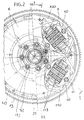
- the plate 11 has cavities 110 for housing axes 7 and cassettes ( Figures 2 to 4). All these forms are easily obtained by molding and it is for this reason that in Figure 2 we have removed the parts 60,160 to make the shape appear well of the plate 11.
- cassettes 10 distributed regularly circumferentially are planned, of course it depends on applications.
- the so-called carrier part 60 is formed between the masses 1 and 2 and is fixed to the external periphery of the plate 11.
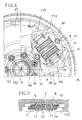
- the supporting part 60 here metallic, for example in stamped sheet metal, present (FIG. 5) at its internal periphery a flange 60B of the same axial orientation which is housed in a recess 25 of the mass 2 made for this purpose.
- the 60B ledge is formed with notches 61 forming mortises and with teeth 62 extending it axially. Teeth 62 initially in alignment with the flange 60B are intended for made to be folded radially with respect to the X-X axis, here radially in the direction opposite to the axis of the assembly.
- the flange 60B with its teeth 62 is intended for housing second elastic friction means with axial action acting between the two masses in a deferred manner. More precisely between the bottom 60C of the cross section of the load-bearing part 60 and the teeth 62, there are successively axially a rotary friction washer 51, a washer application with backlash without backlash 52, and a washer Belleville 55, alternatively a wavy elastic washer bearing directly on teeth 62 to exert a axial force on the pack of washers.
- the washer 52 has, at its internal periphery, legs (not visible) forming tenons engaged in the mortises 61 of the load-bearing part 60.
- the rotary friction washer 51 has at its external periphery of the reinforcement zones in the form of extra thicknesses 51A with notches 51B suitable for cooperating with circumferential clearance with pawns 156 carried by the plate 21 of the mass 2 radially inside the zone annular of the reaction plate 21 intended to cooperate with the clutch friction disc (not shown).
- the reinforcements extend around the washer 52.
- the washer 51 is crenellated at its outer periphery.
- the friction washer 51 is in other words meshed with a clearance clearance with the pins 156 axial orientation of the mass 2.
- the second means of friction are delayed action.
- the washer 51 is made of synthetic material reinforced with fibers and edges of its notches 51B are circular to cooperate with the cylindrical pins 156.
- the Belleville 55 washer also has indentations delimiting the contact and application areas of force on the adjacent application washer 52. Note that the load-bearing part 60 mainly carries the means for friction, only the pawns 156 are carried by the second mass 2.
- the rim 60B has a comb structure with a alternation of notches 61 and teeth 62 bordered by legs of stabilization 70.
- the teeth 62 are thinned relative to the flange 60B of part 60. Notches 63 formed on either side of the teeth 62, facilitate the folding operation.
- stabilization legs 70 on either side of each tooth 62, defined on one side by a notch 63 and of the other by the notch 61. These legs constitute for the tool (not shown) of the support means making it possible to control the folding of the teeth 62 by a solid guide.
- This folding operation can be carried out so known per se: the load-bearing part being placed on a table, a matrix of tools will intervene by repressing Belleville first so as to release the side legs for support guide elements for tools for bending teeth.
- the bearing 15 has a small size, this which makes the double damping flywheel economical, and that the screws fixing 32 are mounted on the internal periphery of the plate 11 and this in the vicinity of the hub 14.
- This hub 14 is stepped and has a larger diameter portion connecting to the tray 11. This portion (the outer periphery thereof) extends radially above the outer ring of the bearing marbles. The smaller diameter portion of the hub serves as support for the inner ring of the ball bearing 15.
- a shoulder 101 is therefore formed in favor of the change in diameter.
- this plate 11 presents at its internal periphery of the holes 232 for passage of the screws 32 and the reaction plate 21 of the second mass 2 present, axially coincident with the holes 232 and the screws 32, passages 132 for access to the heads of the screws 32 and to allow fixing the double flywheel on the crankshaft 34, one or more tools passing in a known manner through the passages 132 to engage and screw the heads of the screws 32.
- the axes 6 are located on a circumference close to that of the holes 232, the passages 132 and the screws 32.
- the axes 6 alternate circumferentially with the passages 132.
- the holes 232 have a countersink for housing the head of the fixing screws 32. These heads are here with hexagon socket.
- the diameter of the passages 132 is slightly larger than the diameter of the screw heads which can thus cross the passages 132.
- the diameter the diameter of the screw heads may be greater than that of passages 132 so that the screws 32 are held captive.
- the larger diameter portion of the hub 14, cylindrical in shape and axially oriented, directed towards the plate 21, is determined by the diameter screws 32.
- first friction means are located at less radially below said passages 132 and axially between the ball bearing 15 and the shoulder 101 formed on the hub 14.
- the inner ring of the ball bearing 15 surrounds the hub 14 and is locked axially in one direction thanks to a circlips 91 engaged in a groove made at the periphery external of the hub 14, in the vicinity of the free end thereof, and axially in the other direction axially in favor of a ring 97, here of the circlip type, engaged in a groove of the hub 14.
- This hub 14 is stepped so that it has a shoulder 101 of transverse orientation in favor of its change in diameter.
- a friction washer 92 is intended to come rub against this shoulder 101.
- This washer belongs to friction means 9 with axial action according to the invention. She is made of synthetic material, such as plastic fiber reinforced. This washer 92 is distant from the plate 21 so that it heats up less than the washer 51 and that it is ventilated through passages 132, which allows also to ventilate the bearing 14.
- These means also include a washer application 93 subjected to the action of an elastic washer with axial action 96 resting on the washer 97.
- the washer 92 is like the washer 51 and presents at its outer periphery projecting radially from the reinforcement 98 with indentations suitable for cooperating with axially oriented pins 99 carried by the reaction plate 21 of mass 2 circularly alternating with the passages 132 hereinafter referred to for convenience as access passages.
- the pawns 99 are forcibly engaged in the plate 21 and mesh with or without play with the notches of the reinforcement zones 98 of the washer 92.
- the notches are not very wide circumferentially and mesh here without play with the pawns 99.
- the application washer 93 has at its periphery internal at least one radial tab 94 engaged in a groove complementary 95 formed in excess thickness at the external periphery of the hub 14.
- the hub 14 thus presents three portions of different diameters with formation of two shoulders namely shoulder 101 and one support shoulder for circlip 97.
- the diameter used centering to the inner ring of the bearing 15 is grooved in correspondence with grooves 95 to allow passage legs 94. For this reason a game appears in the Figures 6 and 7.
- the hub 14 has a larger diameter portion connecting to the plate 11 and delimiting the shoulder 101, a intermediate portion in which the grooves 95 are formed and a portion of smaller diameter used to support the ball bearing inner ring 14.
- the application washer 93 here metallic, is locked in rotation on the hub 14 with possibility of axial displacement under the action of the washer elastic 96 consisting here of an interposed diaphragm axially between the washers 93 and 97.
- the washer 96 consists of a wavy washer.
- the first friction means 9 are therefore trapped between shoulder 101 and washer 97 with formation of a hub sub-assembly 14 - friction means 9.
- the pawns 99 are intended to mesh with or without play circumferential, depending on the applications, with the washer 92 in so that friction occurs, on the one hand, between the washer 92 and the application washer 93 and, on the other hand, with the washer 92 and shoulder 101 belonging to the first mass.
- the washer 92 is therefore actuated by the second mass so that the friction device 9 is worn for the most part by the first mass, being implanted for the most part radially below the access passages 132 and the screws 32.
- the angular movement between the two masses 1 and 2 can thus be of great value.
- first friction means 9 may take action, deferred, before entry into action of the second friction means.
- the pawns 99 mesh with washer 92 with circumferential play lower than that provided between the pins 156 and the washer friction 51.
- stiffening part 160 has holes 111 in axial coincidence with holes 112,113 practiced respectively in the part 60 and in the plate 11.
- the axially aligned holes 111 to 113 define thus passages leading to the face of the reaction plate 21 facing the stage 11. For clarity we have shown in dotted lines in Figure 1 this passage.
- these holes 111 to 113 are arranged on either side of the guide washers 4.5 of cassettes 10.
- These holes 111 to 113 are adjacent (allow a access) to the lateral edges, of transverse orientation, of the cassette 10 for the double steering wheel rest position (figure 4) and allow to ventilate the double steering wheel.
- these rods are integral with a disc serving as support for the plate 11.
- the clutch mechanism has a diaphragm interposed between the cover and the clutch pressure plate.
- the friction disc in contact with the plate 21 and then screw the cover, which varies the inclination of the diaphragm and leads to exerting efforts to compress said diaphragm bearing on the cover and on the pressure plate.
- the washer 92 may have its outer periphery of the legs of axial orientation 192 meshing with 195 axial grooves made in the internal bore (the internal periphery) of the plate 21 in which is mounted the bearing 15.
- the first friction means extend radially below the access passages 132 and screws.
- grooves 195 have a semi circular shape and the top part of the legs 192 has a semi-circular shape complementary.
- axis 6 can be extended by direction of the board 11.
- This extension thus forms a pawn axial orientation 256 meshing with circumferential clearance with a friction washer 151 of plastic material belonging to the second friction means with axial action.
- This washer 151 is interposed axially between the face of the plate 11 facing the plate 21 and an application washer 152 subjected to the action of an elastic washer 155, here a Belleville washer, resting on a shoulder formed at the favor of a plate 360 fixed by riveting on the plate 11.
- the washer 152 has tabs on its outer periphery engaged in grooves of the plate 11 closed by the plate 360.
- the washer 151 has zones reinforcement in 151A with 151B notches of the same type as the reinforcements and the notches of the washer 51 of the figure 1.
- the reinforcements are directed radially towards the axis of the set and the pins 256 are intended to mesh with the notches 151.
- This double flywheel has, at the bearing 15, friction means 9 of the type of those of FIG. 7. These means 9 are, as in FIG. 7, located radially in below the screws 32 and the passages 132.
- the first means of friction 9 according to the invention attenuate the noises caused by second friction means, with axial and delayed action, acting between the two masses 1,2 and located radially above first friction means according to the invention, said noises being due to the cancellation of the meshing game provided between a washer and projections.
- the ends of the springs 8 are supported on plastic cups 17,18 interposed between said ends of springs 8 and the bearing edges of facing windows in the veil 3 and the guide washers 4,5 ( Figures 3 and 4).
- Each cup 17.18 has a centralizer to center the internal springs of the pair of springs 8 and has a block of elastic material at its free end. This block penetrates inside the springs 8.
- the present invention is not limited to the example of embodiment described.
- the means elastic may consist of coil springs 13 with ends shaped into hooks to engage with axes 6 and 7, such springs being visible in FIG. 13 from the aforementioned document WO 95/17618.
- the elastic means can have any of the forms described in this aforementioned document.
- the cassettes 10 can be of the single-spring type as described for example in document WO 94/27062, the spring being mounted in a cylinder, itself mounted articulated on one of the masses, said spring being subjected to the action of a shoulder carried by a piston rod crossing the bottom of the cylinder and hinge mounted on the other mass.
- the elastic means may have action circumferential and act between arms of the veil 3 fixed by riveting, at the axis 6 of Figure 1, to the mass 2 and guide means formed at the outer periphery of the plate 11.
- the plate 11 has supporting parts in stamped look formed in room 60.
- the thrust washer 97 can be fixed by a mounting bayonet type on the hub 14, thanks in particular to the grooves axial formed in the hub 14 and opening into a groove annular.
- the washer 97 has tabs at its internal periphery and at least one tab at its external periphery for its rotation using a tool.
- the washer 97 is force-fitted.
- the elastic means 8, 10 are hinged mounted on the outer periphery of the first mass 1 and articulated on the inner periphery of the second mass 2, so that they have a great length.
- the means of friction 9 are located radially in below said elastic means.
- the elastic means 8, 10 then being mounted at articulation at the internal periphery of the first mass 1 and at articulation at the outer periphery of the second mass 2.
- passages 132 allow better ventilation of the first means of friction 9. Indeed, the fact that these passages 132 have a diameter greater than that of the heads of the screws 32, a small space exists between the outer ring of the bearing and said passages 132, so that passages 132 lead to close to the friction washer 92.
Landscapes
- Engineering & Computer Science (AREA)
- General Engineering & Computer Science (AREA)
- Mechanical Engineering (AREA)
- Physics & Mathematics (AREA)
- Acoustics & Sound (AREA)
- Aviation & Aerospace Engineering (AREA)
- Mechanical Operated Clutches (AREA)
Abstract
Description
- la figure 1 est une vue en coupe axiale d'un double volant amortisseur selon l'invention et ce selon la ligne 1-1 de la figure 2 ;
- la figure 2 est une vue de face du double volant de la figure 1, avec arrachement local laissant apparaítre les cassettes appartenant aux moyens élastiques ;
- la figure 3 est une vue en coupe selon la ligne 3-3 de la figure 2 ;
- la figure 4 est une vue partielle à plus grande échelle correspondant à la figure 2 ;
- la figure 5 est une vue en perspective montrant les moyens de frottement installés dans la pièce porteuse ;
- la figure 6 est une vue à plus grande échelle de la partie centrale de la figure 1 ;
- la figure 7 est une vue partielle analogue à la figure 6 pour un autre exemple de réalisation .
- la figure 8 est une vue analogue à la figure 1 pour un autre exemple de réalisation.
Claims (9)
- Double volant amortisseur de torsion, notamment pour véhicule automobile, comportant deux masses coaxiales (1,2) montées mobiles l'une par rapport à l'autre à l'encontre de moyens élastiques (8) et de moyens de frottement à action axiale (9), dans lequel l'une des masses (1,2), dite première masse (1), est destinée à être fixée à un arbre menant à la faveur de vis (32) traversant des trous (232) pratiqués à la périphérie interne d'un plateau (11) appartenant à la première masse (1), tandis que l'autre masse, dite deuxième masse (2), forme un plateau de réaction (21) pour un embrayage à friction et comporte des passages (132) en coïncidence axiale avec les trous (232) du plateau (11) de la première masse (1) pour accès aux vis (32) et dans lequel la seconde masse (2) est montée tournante par rapport à la première masse (1) à l'aide d'un roulement à billes (15) intervenant entre la périphérie externe d'un moyeu (14) étagé solidaire du plateau (11) de la première masse (1) et la périphérie interne du plateau de réaction (21) de la deuxième masse (2), ledit roulement (15) étant implanté radialement en dessous des passages (132) de la seconde masse (2), tandis qu'un épaulement (101) est formé à la faveur de l'étagement du moyeu (14), caractérisé en ce que les moyens de frottement (9) à action axiale, dits premiers moyens de frottement, sont implantés au moins en majeure partie radialement en dessous desdits passages (132) de la deuxième masse (2) et axialement entre l'épaulement (101) du moyeu (14) de la première masse (1) et le roulement à billes (15).
- Double volant selon la revendication 1, caractérisé en ce que lesdits moyens de frottement (9) comportent une rondelle de frottement (92) interposée entre l'épaulement (101) du moyeu (14) de la première masse (1) et une rondelle d'application (93)calée en rotation sur le moyeu (14) de la première masse (1) en étant soumise à l'action d'un moyen élastique à action axiale (96) prenant appui sur une rondelle (97) calée axialement sur le moyeu (14) de la première masse (1).
- Double volant selon la revendication 2, caractérisé en ce que la rondelle de frottement (92) est propre à engrener avec le plateau de réaction (21) de la seconde masse (2).
- Double volant selon la revendication 3, caractérisé en ce que le plateau de réaction (21) de la première masse (1) porte des pions (99) d'orientation axiale propres à engrener avec des échancrures pratiquées dans un renfort que présente la rondelle de frottement (92) à sa périphérie externe.
- Double volant selon la revendication 3, caractérisé en ce que la rondelle de frottement (92) présente à sa périphérie externe des pattes (192) d'orientation axiale propres à engrener avec des rainures axiales (195) ménagées à la périphérie interne du plateau de réaction (21) de la seconde masse (2).
- Double volant selon la revendication 2, caractérisé en ce que le moyeu (14) présente trois portions de diamètres différents, à savoir une portion de plus grand diamètre se raccordant à un plateau (11), que présente la première masse (1), une portion de diamètre intermédiaire pour calage en rotation de la rondelle d'application (93) et une portion de plus petit diamètre pour montage de la bague interne du roulement à billes (14).
- Double volant selon la revendication 6, caractérisé en ce que la hauteur de l'épaulement (101) du moyeu (14) est globalement égale à la hauteur du roulement à billes (14).
- Double volant selon la revendication 1, caractérisé en ce que les moyens élastiques (8,10) comportent des cassettes (10) articulées sur l'une et l'autre desdites masses.
- Double volant selon la revendication 1, caractérisé en ce qu'il comporte des seconds moyens de frottement, à action axiale et différée intervenant entre les deux masses (1,2), implantés radialement au-dessus des premiers moyens de frottement (9).
Applications Claiming Priority (3)
| Application Number | Priority Date | Filing Date | Title |
|---|---|---|---|
| FR9501542A FR2730292B1 (fr) | 1995-02-08 | 1995-02-08 | Double volant amortisseur de torsion, notamment pour vehicule automobile |
| FR9501542 | 1995-02-08 | ||
| PCT/FR1996/000189 WO1996024785A1 (fr) | 1995-02-08 | 1996-02-06 | Double volant amortisseur de torsion, notamment pour vehicule automobile |
Publications (2)
| Publication Number | Publication Date |
|---|---|
| EP0754276A1 EP0754276A1 (fr) | 1997-01-22 |
| EP0754276B1 true EP0754276B1 (fr) | 1999-12-29 |
Family
ID=9476022
Family Applications (1)
| Application Number | Title | Priority Date | Filing Date |
|---|---|---|---|
| EP96903052A Expired - Lifetime EP0754276B1 (fr) | 1995-02-08 | 1996-02-06 | Double volant amortisseur de torsion, notamment pour vehicule automobile |
Country Status (4)
| Country | Link |
|---|---|
| EP (1) | EP0754276B1 (fr) |
| DE (1) | DE19680167B4 (fr) |
| FR (1) | FR2730292B1 (fr) |
| WO (1) | WO1996024785A1 (fr) |
Families Citing this family (5)
| Publication number | Priority date | Publication date | Assignee | Title |
|---|---|---|---|---|
| FR2756895B1 (fr) * | 1996-12-06 | 1999-01-15 | Renault | Dispositif de positionnement d'un volant d'inertie de moteur a combustion interne |
| FR2771786B1 (fr) | 1997-11-28 | 2000-02-11 | Valeo | Dispositif amortisseur de torsion et ensemble unitaire de frottement pour un tel dispositif |
| FR2778717B1 (fr) * | 1998-05-13 | 2000-08-11 | Valeo | Dispositif amortisseur de torsion comportant un dispositif de frottement ayant une matiere de frottement ne generant pas de bruit en fonctionnement |
| DE102012218923A1 (de) * | 2012-10-17 | 2014-04-17 | Zf Friedrichshafen Ag | Drehschwingungsdämpfungsanordnung mit Schwingungsdämpfung |
| DE102012218924A1 (de) * | 2012-10-17 | 2014-04-17 | Zf Friedrichshafen Ag | Drehschwingungsdämpfungsanordnung mit drehzahlabhängiger Steifigkeit |
Family Cites Families (6)
| Publication number | Priority date | Publication date | Assignee | Title |
|---|---|---|---|---|
| FR2556434B1 (fr) * | 1983-11-15 | 1991-08-09 | Luk Lamellen & Kupplungsbau | Dispositif pour compenser des a-coups dans le mouvement de rotation d'un moteur |
| FR2690722B1 (fr) * | 1992-04-30 | 1994-09-16 | Valeo | Double volant amortisseur, notamment pour véhicule automobile. |
| SE501308C2 (sv) * | 1993-05-19 | 1995-01-09 | Saab Scania Ab | Dubbelmassesvänghjul |
| FR2706006B1 (fr) * | 1993-06-02 | 1995-07-07 | Valeo | Volant amortisseur notamment pour véhicule automobile. |
| FR2706963B1 (fr) * | 1993-06-25 | 1995-09-15 | Valeo | |
| FR2716511B1 (fr) * | 1993-12-23 | 1996-05-03 | Valeo | Volant amortisseur, notamment pour véhicule automobile . |
-
1995
- 1995-02-08 FR FR9501542A patent/FR2730292B1/fr not_active Expired - Fee Related
-
1996
- 1996-02-06 WO PCT/FR1996/000189 patent/WO1996024785A1/fr not_active Ceased
- 1996-02-06 EP EP96903052A patent/EP0754276B1/fr not_active Expired - Lifetime
- 1996-02-06 DE DE19680167T patent/DE19680167B4/de not_active Expired - Lifetime
Also Published As
| Publication number | Publication date |
|---|---|
| FR2730292B1 (fr) | 1997-04-04 |
| FR2730292A1 (fr) | 1996-08-09 |
| WO1996024785A1 (fr) | 1996-08-15 |
| DE19680167T1 (de) | 1997-10-02 |
| DE19680167B4 (de) | 2006-08-10 |
| EP0754276A1 (fr) | 1997-01-22 |
Similar Documents
| Publication | Publication Date | Title |
|---|---|---|
| EP0341133B1 (fr) | Dispositif amortisseur de torsion à flans élastiques, notamment pour véhicule automobile | |
| EP0715695B1 (fr) | Volant amortisseur notamment pour vehicule automobile | |
| FR2614080A1 (fr) | Dispositif amortisseur de torsion a palier de centrage | |
| FR2676789A1 (fr) | Amortisseur de torsion, notamment pour vehicules automobiles. | |
| FR2611245A1 (fr) | Disque de friction d'embrayage avec preamortisseur | |
| FR2690722A1 (fr) | Double volant amortisseur, notamment pour véhicule automobile. | |
| FR2646692A1 (fr) | Dispositif amortisseur de torsion, notamment pour vehicules automobiles | |
| FR2613800A1 (fr) | Dispositif amortisseur de torsion, notamment disque de friction d'embrayage pour vehicule automobile | |
| EP0745196B1 (fr) | Volant amortisseur, notamment pour vehicules automobiles | |
| EP0859920B1 (fr) | Double volant amortisseur, notamment pour vehicule automobile, comportant des moyens perfectionnes d'amortissement par friction des vibrations | |
| EP0738378B1 (fr) | Amortisseur de torsion, notamment friction d'embrayage pour vehicule automobile | |
| FR3070737A1 (fr) | Dispositif damortissement pendulaire | |
| FR2691223A1 (fr) | Dispositif d'amortissement pour un embrayage à disques de friction multiples. | |
| EP0754276B1 (fr) | Double volant amortisseur de torsion, notamment pour vehicule automobile | |
| FR2735548A1 (fr) | Dispositif amortisseur de torsion | |
| FR2733809A1 (fr) | Amortisseur de torsion a rondelle de commande, notamment friction d'embrayage pour vehicule automobile | |
| EP0586290B1 (fr) | Amortisseur de torsion, notamment disque de friction d'embrayage pour véhicule automobile | |
| EP0736149B1 (fr) | Dispositif amortisseur de torsion | |
| FR2626335A1 (fr) | Double volant amortisseur notamment pour vehicules automobiles | |
| FR2627831A1 (fr) | Amortisseur de vibrations de torsion a friction en fonction de l'angle de torsion | |
| FR2625782A1 (fr) | Amortisseur de torsion concentrique notamment pour vehicules automobiles | |
| FR2633360A1 (fr) | Dispositif amortisseur de torsion, notamment pour vehicule automobile | |
| EP0746700B1 (fr) | Dispositif d'amortissement de torsion | |
| FR2675872A1 (fr) | Double volant amortisseur a double amortissement par frottement, notamment pour vehicules automobiles. | |
| WO1996024786A1 (fr) | Double volant amortisseur de torsion, notamment pour vehicule automobile |
Legal Events
| Date | Code | Title | Description |
|---|---|---|---|
| PUAI | Public reference made under article 153(3) epc to a published international application that has entered the european phase |
Free format text: ORIGINAL CODE: 0009012 |
|
| 17P | Request for examination filed |
Effective date: 19961021 |
|
| AK | Designated contracting states |
Kind code of ref document: A1 Designated state(s): FR IT |
|
| GRAG | Despatch of communication of intention to grant |
Free format text: ORIGINAL CODE: EPIDOS AGRA |
|
| 17Q | First examination report despatched |
Effective date: 19990211 |
|
| GRAG | Despatch of communication of intention to grant |
Free format text: ORIGINAL CODE: EPIDOS AGRA |
|
| GRAH | Despatch of communication of intention to grant a patent |
Free format text: ORIGINAL CODE: EPIDOS IGRA |
|
| GRAH | Despatch of communication of intention to grant a patent |
Free format text: ORIGINAL CODE: EPIDOS IGRA |
|
| GRAA | (expected) grant |
Free format text: ORIGINAL CODE: 0009210 |
|
| AK | Designated contracting states |
Kind code of ref document: B1 Designated state(s): FR IT |
|
| ITF | It: translation for a ep patent filed | ||
| PLBE | No opposition filed within time limit |
Free format text: ORIGINAL CODE: 0009261 |
|
| STAA | Information on the status of an ep patent application or granted ep patent |
Free format text: STATUS: NO OPPOSITION FILED WITHIN TIME LIMIT |
|
| 26N | No opposition filed | ||
| REG | Reference to a national code |
Ref country code: FR Ref legal event code: TP |
|
| PGFP | Annual fee paid to national office [announced via postgrant information from national office to epo] |
Ref country code: IT Payment date: 20060228 Year of fee payment: 11 |
|
| PG25 | Lapsed in a contracting state [announced via postgrant information from national office to epo] |
Ref country code: IT Free format text: LAPSE BECAUSE OF NON-PAYMENT OF DUE FEES Effective date: 20070206 |
|
| REG | Reference to a national code |
Ref country code: FR Ref legal event code: PLFP Year of fee payment: 20 |
|
| PGFP | Annual fee paid to national office [announced via postgrant information from national office to epo] |
Ref country code: FR Payment date: 20150302 Year of fee payment: 20 |