EP0754265B1 - Hochisolierende verbindungsstäbe und verfahren zu ihrer herstellung und ihrer anwendung in hochisolierten zusammengesetzten wänden - Google Patents
Hochisolierende verbindungsstäbe und verfahren zu ihrer herstellung und ihrer anwendung in hochisolierten zusammengesetzten wänden Download PDFInfo
- Publication number
- EP0754265B1 EP0754265B1 EP95914923A EP95914923A EP0754265B1 EP 0754265 B1 EP0754265 B1 EP 0754265B1 EP 95914923 A EP95914923 A EP 95914923A EP 95914923 A EP95914923 A EP 95914923A EP 0754265 B1 EP0754265 B1 EP 0754265B1
- Authority
- EP
- European Patent Office
- Prior art keywords
- connector
- layer
- segment
- insulating
- composite wall
- Prior art date
- Legal status (The legal status is an assumption and is not a legal conclusion. Google has not performed a legal analysis and makes no representation as to the accuracy of the status listed.)
- Expired - Lifetime
Links
- 239000002131 composite material Substances 0.000 title claims abstract description 55
- 238000004519 manufacturing process Methods 0.000 title claims description 27
- 238000000034 method Methods 0.000 title claims description 21
- 239000000835 fiber Substances 0.000 claims abstract description 24
- 239000004033 plastic Substances 0.000 claims abstract description 23
- 229920003023 plastic Polymers 0.000 claims abstract description 23
- 238000004873 anchoring Methods 0.000 claims abstract description 21
- 239000011810 insulating material Substances 0.000 claims abstract description 19
- 239000000463 material Substances 0.000 claims description 52
- 239000004567 concrete Substances 0.000 claims description 41
- 230000000149 penetrating effect Effects 0.000 claims description 25
- 229920005989 resin Polymers 0.000 claims description 20
- 239000011347 resin Substances 0.000 claims description 20
- 238000000465 moulding Methods 0.000 claims description 10
- 239000000956 alloy Substances 0.000 claims description 6
- 229910045601 alloy Inorganic materials 0.000 claims description 6
- 229920001748 polybutylene Polymers 0.000 claims description 6
- 239000004417 polycarbonate Substances 0.000 claims description 6
- 229920000515 polycarbonate Polymers 0.000 claims description 6
- 239000004593 Epoxy Substances 0.000 claims description 5
- 229920006327 polystyrene foam Polymers 0.000 claims description 5
- 229920001187 thermosetting polymer Polymers 0.000 claims description 4
- 239000000919 ceramic Substances 0.000 claims description 3
- 239000011152 fibreglass Substances 0.000 claims description 3
- 239000003365 glass fiber Substances 0.000 claims description 3
- 239000000203 mixture Substances 0.000 claims description 3
- OKTJSMMVPCPJKN-UHFFFAOYSA-N Carbon Chemical compound [C] OKTJSMMVPCPJKN-UHFFFAOYSA-N 0.000 claims description 2
- 229910052799 carbon Inorganic materials 0.000 claims 1
- 230000000694 effects Effects 0.000 abstract description 10
- 239000012260 resinous material Substances 0.000 abstract description 7
- 238000002347 injection Methods 0.000 abstract description 6
- 239000007924 injection Substances 0.000 abstract description 6
- 238000009413 insulation Methods 0.000 description 15
- 230000035515 penetration Effects 0.000 description 9
- 239000002184 metal Substances 0.000 description 8
- 238000005452 bending Methods 0.000 description 7
- 230000015572 biosynthetic process Effects 0.000 description 7
- 238000010276 construction Methods 0.000 description 4
- 238000003780 insertion Methods 0.000 description 4
- 230000037431 insertion Effects 0.000 description 4
- ZOXJGFHDIHLPTG-UHFFFAOYSA-N Boron Chemical compound [B] ZOXJGFHDIHLPTG-UHFFFAOYSA-N 0.000 description 3
- 229910052796 boron Inorganic materials 0.000 description 3
- 238000001746 injection moulding Methods 0.000 description 3
- 229920005668 polycarbonate resin Polymers 0.000 description 3
- 239000004431 polycarbonate resin Substances 0.000 description 3
- 239000000758 substrate Substances 0.000 description 3
- 229920000049 Carbon (fiber) Polymers 0.000 description 2
- 239000011230 binding agent Substances 0.000 description 2
- 239000004566 building material Substances 0.000 description 2
- 239000004917 carbon fiber Substances 0.000 description 2
- 239000004568 cement Substances 0.000 description 2
- 239000006260 foam Substances 0.000 description 2
- 239000011396 hydraulic cement Substances 0.000 description 2
- 239000012774 insulation material Substances 0.000 description 2
- -1 polybutylene Polymers 0.000 description 2
- 230000008569 process Effects 0.000 description 2
- 238000010107 reaction injection moulding Methods 0.000 description 2
- 238000001721 transfer moulding Methods 0.000 description 2
- XLYOFNOQVPJJNP-UHFFFAOYSA-N water Substances O XLYOFNOQVPJJNP-UHFFFAOYSA-N 0.000 description 2
- 239000002023 wood Substances 0.000 description 2
- 239000004677 Nylon Substances 0.000 description 1
- 239000004793 Polystyrene Substances 0.000 description 1
- 229920005830 Polyurethane Foam Polymers 0.000 description 1
- 229910000831 Steel Inorganic materials 0.000 description 1
- 239000004964 aerogel Substances 0.000 description 1
- 230000008901 benefit Effects 0.000 description 1
- UGGQKDBXXFIWJD-UHFFFAOYSA-N calcium;dihydroxy(oxo)silane;hydrate Chemical compound O.[Ca].O[Si](O)=O UGGQKDBXXFIWJD-UHFFFAOYSA-N 0.000 description 1
- 238000005266 casting Methods 0.000 description 1
- 239000004020 conductor Substances 0.000 description 1
- 230000007812 deficiency Effects 0.000 description 1
- 238000005516 engineering process Methods 0.000 description 1
- 239000003822 epoxy resin Substances 0.000 description 1
- 238000001125 extrusion Methods 0.000 description 1
- 239000013305 flexible fiber Substances 0.000 description 1
- 239000006261 foam material Substances 0.000 description 1
- 239000011521 glass Substances 0.000 description 1
- 239000010439 graphite Substances 0.000 description 1
- 229910002804 graphite Inorganic materials 0.000 description 1
- LNEPOXFFQSENCJ-UHFFFAOYSA-N haloperidol Chemical compound C1CC(O)(C=2C=CC(Cl)=CC=2)CCN1CCCC(=O)C1=CC=C(F)C=C1 LNEPOXFFQSENCJ-UHFFFAOYSA-N 0.000 description 1
- 230000006872 improvement Effects 0.000 description 1
- 230000003993 interaction Effects 0.000 description 1
- 238000003754 machining Methods 0.000 description 1
- 239000002557 mineral fiber Substances 0.000 description 1
- 229920001778 nylon Polymers 0.000 description 1
- 229920000647 polyepoxide Polymers 0.000 description 1
- 229920000728 polyester Polymers 0.000 description 1
- 229920001228 polyisocyanate Polymers 0.000 description 1
- 239000005056 polyisocyanate Substances 0.000 description 1
- 229920000642 polymer Polymers 0.000 description 1
- 229920005596 polymer binder Polymers 0.000 description 1
- 239000002491 polymer binding agent Substances 0.000 description 1
- ODGAOXROABLFNM-UHFFFAOYSA-N polynoxylin Chemical compound O=C.NC(N)=O ODGAOXROABLFNM-UHFFFAOYSA-N 0.000 description 1
- 229920002223 polystyrene Polymers 0.000 description 1
- 239000011496 polyurethane foam Substances 0.000 description 1
- 239000011435 rock Substances 0.000 description 1
- 239000004576 sand Substances 0.000 description 1
- 238000000926 separation method Methods 0.000 description 1
- 230000007480 spreading Effects 0.000 description 1
- 238000003892 spreading Methods 0.000 description 1
- 239000010959 steel Substances 0.000 description 1
- 239000004639 urea-formaldehyde foam Substances 0.000 description 1
- 229920001567 vinyl ester resin Polymers 0.000 description 1
Images

Classifications
-
- B—PERFORMING OPERATIONS; TRANSPORTING
- B32—LAYERED PRODUCTS
- B32B—LAYERED PRODUCTS, i.e. PRODUCTS BUILT-UP OF STRATA OF FLAT OR NON-FLAT, e.g. CELLULAR OR HONEYCOMB, FORM
- B32B7/00—Layered products characterised by the relation between layers; Layered products characterised by the relative orientation of features between layers, or by the relative values of a measurable parameter between layers, i.e. products comprising layers having different physical, chemical or physicochemical properties; Layered products characterised by the interconnection of layers
- B32B7/04—Interconnection of layers
- B32B7/08—Interconnection of layers by mechanical means
-
- B—PERFORMING OPERATIONS; TRANSPORTING
- B28—WORKING CEMENT, CLAY, OR STONE
- B28B—SHAPING CLAY OR OTHER CERAMIC COMPOSITIONS; SHAPING SLAG; SHAPING MIXTURES CONTAINING CEMENTITIOUS MATERIAL, e.g. PLASTER
- B28B19/00—Machines or methods for applying the material to surfaces to form a permanent layer thereon
- B28B19/003—Machines or methods for applying the material to surfaces to form a permanent layer thereon to insulating material
-
- B—PERFORMING OPERATIONS; TRANSPORTING
- B29—WORKING OF PLASTICS; WORKING OF SUBSTANCES IN A PLASTIC STATE IN GENERAL
- B29C—SHAPING OR JOINING OF PLASTICS; SHAPING OF MATERIAL IN A PLASTIC STATE, NOT OTHERWISE PROVIDED FOR; AFTER-TREATMENT OF THE SHAPED PRODUCTS, e.g. REPAIRING
- B29C37/00—Component parts, details, accessories or auxiliary operations, not covered by group B29C33/00 or B29C35/00
- B29C37/0078—Measures or configurations for obtaining anchoring effects in the contact areas between layers
- B29C37/0082—Mechanical anchoring
-
- B—PERFORMING OPERATIONS; TRANSPORTING
- B32—LAYERED PRODUCTS
- B32B—LAYERED PRODUCTS, i.e. PRODUCTS BUILT-UP OF STRATA OF FLAT OR NON-FLAT, e.g. CELLULAR OR HONEYCOMB, FORM
- B32B13/00—Layered products comprising a a layer of water-setting substance, e.g. concrete, plaster, asbestos cement, or like builders' material
- B32B13/04—Layered products comprising a a layer of water-setting substance, e.g. concrete, plaster, asbestos cement, or like builders' material comprising such water setting substance as the main or only constituent of a layer, which is next to another layer of the same or of a different material
- B32B13/045—Layered products comprising a a layer of water-setting substance, e.g. concrete, plaster, asbestos cement, or like builders' material comprising such water setting substance as the main or only constituent of a layer, which is next to another layer of the same or of a different material of foam
-
- B—PERFORMING OPERATIONS; TRANSPORTING
- B32—LAYERED PRODUCTS
- B32B—LAYERED PRODUCTS, i.e. PRODUCTS BUILT-UP OF STRATA OF FLAT OR NON-FLAT, e.g. CELLULAR OR HONEYCOMB, FORM
- B32B13/00—Layered products comprising a a layer of water-setting substance, e.g. concrete, plaster, asbestos cement, or like builders' material
- B32B13/04—Layered products comprising a a layer of water-setting substance, e.g. concrete, plaster, asbestos cement, or like builders' material comprising such water setting substance as the main or only constituent of a layer, which is next to another layer of the same or of a different material
- B32B13/12—Layered products comprising a a layer of water-setting substance, e.g. concrete, plaster, asbestos cement, or like builders' material comprising such water setting substance as the main or only constituent of a layer, which is next to another layer of the same or of a different material of synthetic resin
-
- B—PERFORMING OPERATIONS; TRANSPORTING
- B32—LAYERED PRODUCTS
- B32B—LAYERED PRODUCTS, i.e. PRODUCTS BUILT-UP OF STRATA OF FLAT OR NON-FLAT, e.g. CELLULAR OR HONEYCOMB, FORM
- B32B17/00—Layered products essentially comprising sheet glass, or glass, slag, or like fibres
- B32B17/02—Layered products essentially comprising sheet glass, or glass, slag, or like fibres in the form of fibres or filaments
-
- B—PERFORMING OPERATIONS; TRANSPORTING
- B32—LAYERED PRODUCTS
- B32B—LAYERED PRODUCTS, i.e. PRODUCTS BUILT-UP OF STRATA OF FLAT OR NON-FLAT, e.g. CELLULAR OR HONEYCOMB, FORM
- B32B27/00—Layered products comprising a layer of synthetic resin
- B32B27/30—Layered products comprising a layer of synthetic resin comprising vinyl (co)polymers; comprising acrylic (co)polymers
- B32B27/302—Layered products comprising a layer of synthetic resin comprising vinyl (co)polymers; comprising acrylic (co)polymers comprising aromatic vinyl (co)polymers, e.g. styrenic (co)polymers
-
- B—PERFORMING OPERATIONS; TRANSPORTING
- B32—LAYERED PRODUCTS
- B32B—LAYERED PRODUCTS, i.e. PRODUCTS BUILT-UP OF STRATA OF FLAT OR NON-FLAT, e.g. CELLULAR OR HONEYCOMB, FORM
- B32B5/00—Layered products characterised by the non- homogeneity or physical structure, i.e. comprising a fibrous, filamentary, particulate or foam layer; Layered products characterised by having a layer differing constitutionally or physically in different parts
- B32B5/18—Layered products characterised by the non- homogeneity or physical structure, i.e. comprising a fibrous, filamentary, particulate or foam layer; Layered products characterised by having a layer differing constitutionally or physically in different parts characterised by features of a layer of foamed material
-
- B—PERFORMING OPERATIONS; TRANSPORTING
- B32—LAYERED PRODUCTS
- B32B—LAYERED PRODUCTS, i.e. PRODUCTS BUILT-UP OF STRATA OF FLAT OR NON-FLAT, e.g. CELLULAR OR HONEYCOMB, FORM
- B32B7/00—Layered products characterised by the relation between layers; Layered products characterised by the relative orientation of features between layers, or by the relative values of a measurable parameter between layers, i.e. products comprising layers having different physical, chemical or physicochemical properties; Layered products characterised by the interconnection of layers
- B32B7/04—Interconnection of layers
- B32B7/12—Interconnection of layers using interposed adhesives or interposed materials with bonding properties
-
- E—FIXED CONSTRUCTIONS
- E04—BUILDING
- E04C—STRUCTURAL ELEMENTS; BUILDING MATERIALS
- E04C2/00—Building elements of relatively thin form for the construction of parts of buildings, e.g. sheet materials, slabs, or panels
- E04C2/02—Building elements of relatively thin form for the construction of parts of buildings, e.g. sheet materials, slabs, or panels characterised by specified materials
- E04C2/26—Building elements of relatively thin form for the construction of parts of buildings, e.g. sheet materials, slabs, or panels characterised by specified materials composed of materials covered by two or more of groups E04C2/04, E04C2/08, E04C2/10 or of materials covered by one of these groups with a material not specified in one of the groups
- E04C2/284—Building elements of relatively thin form for the construction of parts of buildings, e.g. sheet materials, slabs, or panels characterised by specified materials composed of materials covered by two or more of groups E04C2/04, E04C2/08, E04C2/10 or of materials covered by one of these groups with a material not specified in one of the groups at least one of the materials being insulating
- E04C2/288—Building elements of relatively thin form for the construction of parts of buildings, e.g. sheet materials, slabs, or panels characterised by specified materials composed of materials covered by two or more of groups E04C2/04, E04C2/08, E04C2/10 or of materials covered by one of these groups with a material not specified in one of the groups at least one of the materials being insulating composed of insulating material and concrete, stone or stone-like material
-
- F—MECHANICAL ENGINEERING; LIGHTING; HEATING; WEAPONS; BLASTING
- F16—ENGINEERING ELEMENTS AND UNITS; GENERAL MEASURES FOR PRODUCING AND MAINTAINING EFFECTIVE FUNCTIONING OF MACHINES OR INSTALLATIONS; THERMAL INSULATION IN GENERAL
- F16B—DEVICES FOR FASTENING OR SECURING CONSTRUCTIONAL ELEMENTS OR MACHINE PARTS TOGETHER, e.g. NAILS, BOLTS, CIRCLIPS, CLAMPS, CLIPS OR WEDGES; JOINTS OR JOINTING
- F16B15/00—Nails; Staples
- F16B15/02—Nails; Staples with specially-shaped heads, e.g. with enlarged surfaces
-
- F—MECHANICAL ENGINEERING; LIGHTING; HEATING; WEAPONS; BLASTING
- F16—ENGINEERING ELEMENTS AND UNITS; GENERAL MEASURES FOR PRODUCING AND MAINTAINING EFFECTIVE FUNCTIONING OF MACHINES OR INSTALLATIONS; THERMAL INSULATION IN GENERAL
- F16B—DEVICES FOR FASTENING OR SECURING CONSTRUCTIONAL ELEMENTS OR MACHINE PARTS TOGETHER, e.g. NAILS, BOLTS, CIRCLIPS, CLAMPS, CLIPS OR WEDGES; JOINTS OR JOINTING
- F16B19/00—Bolts without screw-thread; Pins, including deformable elements; Rivets
- F16B19/14—Bolts or the like for shooting into concrete constructions, metal walls or the like by means of detonation-operated nailing tools
-
- F—MECHANICAL ENGINEERING; LIGHTING; HEATING; WEAPONS; BLASTING
- F16—ENGINEERING ELEMENTS AND UNITS; GENERAL MEASURES FOR PRODUCING AND MAINTAINING EFFECTIVE FUNCTIONING OF MACHINES OR INSTALLATIONS; THERMAL INSULATION IN GENERAL
- F16B—DEVICES FOR FASTENING OR SECURING CONSTRUCTIONAL ELEMENTS OR MACHINE PARTS TOGETHER, e.g. NAILS, BOLTS, CIRCLIPS, CLAMPS, CLIPS OR WEDGES; JOINTS OR JOINTING
- F16B21/00—Means for preventing relative axial movement of a pin, spigot, shaft or the like and a member surrounding it; Stud-and-socket releasable fastenings
-
- F—MECHANICAL ENGINEERING; LIGHTING; HEATING; WEAPONS; BLASTING
- F16—ENGINEERING ELEMENTS AND UNITS; GENERAL MEASURES FOR PRODUCING AND MAINTAINING EFFECTIVE FUNCTIONING OF MACHINES OR INSTALLATIONS; THERMAL INSULATION IN GENERAL
- F16B—DEVICES FOR FASTENING OR SECURING CONSTRUCTIONAL ELEMENTS OR MACHINE PARTS TOGETHER, e.g. NAILS, BOLTS, CIRCLIPS, CLAMPS, CLIPS OR WEDGES; JOINTS OR JOINTING
- F16B5/00—Joining sheets or plates, e.g. panels, to one another or to strips or bars parallel to them
- F16B5/04—Joining sheets or plates, e.g. panels, to one another or to strips or bars parallel to them by means of riveting
-
- B—PERFORMING OPERATIONS; TRANSPORTING
- B29—WORKING OF PLASTICS; WORKING OF SUBSTANCES IN A PLASTIC STATE IN GENERAL
- B29K—INDEXING SCHEME ASSOCIATED WITH SUBCLASSES B29B, B29C OR B29D, RELATING TO MOULDING MATERIALS OR TO MATERIALS FOR MOULDS, REINFORCEMENTS, FILLERS OR PREFORMED PARTS, e.g. INSERTS
- B29K2105/00—Condition, form or state of moulded material or of the material to be shaped
- B29K2105/24—Condition, form or state of moulded material or of the material to be shaped crosslinked or vulcanised
- B29K2105/243—Partially cured
-
- B—PERFORMING OPERATIONS; TRANSPORTING
- B32—LAYERED PRODUCTS
- B32B—LAYERED PRODUCTS, i.e. PRODUCTS BUILT-UP OF STRATA OF FLAT OR NON-FLAT, e.g. CELLULAR OR HONEYCOMB, FORM
- B32B2262/00—Composition or structural features of fibres which form a fibrous or filamentary layer or are present as additives
- B32B2262/10—Inorganic fibres
- B32B2262/101—Glass fibres
-
- B—PERFORMING OPERATIONS; TRANSPORTING
- B32—LAYERED PRODUCTS
- B32B—LAYERED PRODUCTS, i.e. PRODUCTS BUILT-UP OF STRATA OF FLAT OR NON-FLAT, e.g. CELLULAR OR HONEYCOMB, FORM
- B32B2266/00—Composition of foam
- B32B2266/02—Organic
- B32B2266/0214—Materials belonging to B32B27/00
- B32B2266/0221—Vinyl resin
- B32B2266/0228—Aromatic vinyl resin, e.g. styrenic (co)polymers
-
- B—PERFORMING OPERATIONS; TRANSPORTING
- B32—LAYERED PRODUCTS
- B32B—LAYERED PRODUCTS, i.e. PRODUCTS BUILT-UP OF STRATA OF FLAT OR NON-FLAT, e.g. CELLULAR OR HONEYCOMB, FORM
- B32B2307/00—Properties of the layers or laminate
- B32B2307/30—Properties of the layers or laminate having particular thermal properties
- B32B2307/304—Insulating
-
- B—PERFORMING OPERATIONS; TRANSPORTING
- B32—LAYERED PRODUCTS
- B32B—LAYERED PRODUCTS, i.e. PRODUCTS BUILT-UP OF STRATA OF FLAT OR NON-FLAT, e.g. CELLULAR OR HONEYCOMB, FORM
- B32B2307/00—Properties of the layers or laminate
- B32B2307/50—Properties of the layers or laminate having particular mechanical properties
- B32B2307/542—Shear strength
-
- B—PERFORMING OPERATIONS; TRANSPORTING
- B32—LAYERED PRODUCTS
- B32B—LAYERED PRODUCTS, i.e. PRODUCTS BUILT-UP OF STRATA OF FLAT OR NON-FLAT, e.g. CELLULAR OR HONEYCOMB, FORM
- B32B2315/00—Other materials containing non-metallic inorganic compounds not provided for in groups B32B2311/00 - B32B2313/04
- B32B2315/06—Concrete
-
- B—PERFORMING OPERATIONS; TRANSPORTING
- B32—LAYERED PRODUCTS
- B32B—LAYERED PRODUCTS, i.e. PRODUCTS BUILT-UP OF STRATA OF FLAT OR NON-FLAT, e.g. CELLULAR OR HONEYCOMB, FORM
- B32B2315/00—Other materials containing non-metallic inorganic compounds not provided for in groups B32B2311/00 - B32B2313/04
- B32B2315/08—Glass
- B32B2315/085—Glass fiber cloth or fabric
-
- B—PERFORMING OPERATIONS; TRANSPORTING
- B32—LAYERED PRODUCTS
- B32B—LAYERED PRODUCTS, i.e. PRODUCTS BUILT-UP OF STRATA OF FLAT OR NON-FLAT, e.g. CELLULAR OR HONEYCOMB, FORM
- B32B2325/00—Polymers of vinyl-aromatic compounds, e.g. polystyrene
-
- B—PERFORMING OPERATIONS; TRANSPORTING
- B32—LAYERED PRODUCTS
- B32B—LAYERED PRODUCTS, i.e. PRODUCTS BUILT-UP OF STRATA OF FLAT OR NON-FLAT, e.g. CELLULAR OR HONEYCOMB, FORM
- B32B2607/00—Walls, panels
-
- E—FIXED CONSTRUCTIONS
- E04—BUILDING
- E04C—STRUCTURAL ELEMENTS; BUILDING MATERIALS
- E04C2/00—Building elements of relatively thin form for the construction of parts of buildings, e.g. sheet materials, slabs, or panels
- E04C2/02—Building elements of relatively thin form for the construction of parts of buildings, e.g. sheet materials, slabs, or panels characterised by specified materials
- E04C2/04—Building elements of relatively thin form for the construction of parts of buildings, e.g. sheet materials, slabs, or panels characterised by specified materials of concrete or other stone-like material; of asbestos cement; of cement and other mineral fibres
- E04C2/044—Building elements of relatively thin form for the construction of parts of buildings, e.g. sheet materials, slabs, or panels characterised by specified materials of concrete or other stone-like material; of asbestos cement; of cement and other mineral fibres of concrete
- E04C2002/045—Building elements of relatively thin form for the construction of parts of buildings, e.g. sheet materials, slabs, or panels characterised by specified materials of concrete or other stone-like material; of asbestos cement; of cement and other mineral fibres of concrete with two parallel leaves connected by tie anchors
- E04C2002/047—Pin or rod shaped anchors
-
- Y—GENERAL TAGGING OF NEW TECHNOLOGICAL DEVELOPMENTS; GENERAL TAGGING OF CROSS-SECTIONAL TECHNOLOGIES SPANNING OVER SEVERAL SECTIONS OF THE IPC; TECHNICAL SUBJECTS COVERED BY FORMER USPC CROSS-REFERENCE ART COLLECTIONS [XRACs] AND DIGESTS
- Y10—TECHNICAL SUBJECTS COVERED BY FORMER USPC
- Y10S—TECHNICAL SUBJECTS COVERED BY FORMER USPC CROSS-REFERENCE ART COLLECTIONS [XRACs] AND DIGESTS
- Y10S411/00—Expanded, threaded, driven, headed, tool-deformed, or locked-threaded fastener
- Y10S411/904—Fastener or fastener element composed of nonmetallic material
- Y10S411/908—Resinous material
Definitions
- This invention relates to highly insulative connector rods used to secure together multiple layers of material within a composite wall structure.
- the high shear strength connector rods have a high R value and are used to join together a highly insulating layer sandwiched between concrete layers on either side of the insulating layer
- one of the least expensive and strongest building materials that has found extensive use in the construction industry is concrete, which is formed from a mixture comprising a hydraulic cement binder, water and a relatively low cost and high compressive strength aggregate material, such as rocks, pebbles and sand. Together these form a relatively high strength, low cost building material.
- concrete has the drawback of offering poor insulation compared to highly insulating materials such as fiberglass or polymeric foam materials. While an 8 inch slab of concrete has an R value (or thermal resistance) of 0.64, a 1 inch panel of polystyrene has an R value of 5.0. However, these latter materials, while highly insulative, also have the drawback of offering little in terms of structural strength or integrity.
- Such structural bridging is necessary in order for the two-wall structure to have high strength and integrity and to prevent the two walls from collapsing together or separating apart during construction and subsequent use of the building. This has usually been accomplished through the use of metal studs, bolts, or beams. However, because metal is a very good conductive material (and therefore has very low insulation), such studs, bolts, beams, or other means for structurally bridging the two walls together also create a conduit or conductive thermal bridge across which heat can readily flow, notwithstanding their being surrounded by ample amounts of an insulating material. As a result, heat can rapidly flow from a relatively warm inside wall to a colder outside wall during cold weather, for example.
- an insulating material may have a relatively high R value, the net R value of the two walls can often be far less, thus negating or minimizing the effect of adding additional layers of insulation.
- R value the net R value of the two walls can often be far less, thus negating or minimizing the effect of adding additional layers of insulation.
- the highly insulating effect of the polystyrene foam is substantially lost due to the thermal bridging effect of the highly conductive metal studs or connectors.
- the polystyrene foam or other high R-value insulating material is unable to impart the full level of insulation possible because of the conductive thermal bridges.
- the manufacture of the Long '733 Patent connector requires at least five basic manufacturing steps, and possibly more, due to the materials used to form the connector, as well as the design of the connector.
- the Long '733 Patent Connector includes two separate pieces formed by different manufacturing methods and from different materials which must be fastened together to form the Long '733 Patent connector.
- the flat, elongate portion which extends through the entire length of the Long '733 Patent connector is formed from a continuous fiber, such as glass, graphite or boron, which has been impregnated with a polyester vinyl ester epoxy or other suitable polymer binder.
- a continuous fiber such as glass, graphite or boron
- the most economical and reliable method of forming a flat, elongate rod having the proper dimensions is by pultrusion. Because pultrusion (like extrusion) yields articles of uniform cross section, the flat, elongate portion must further be cut to length and then machined in order to provide the tapered portions that are necessary to retain the connector within the hardened concrete slabs. Hence, three separate manufacturing steps are required to create the flat, elongate portion alone.
- the central sleeve portion must be separately molded by, for example, injection molding, and then be separately mounted over the central portion of the flat, elongate portion (column 3, lines 2-4).
- One of the purposes of the central sleeve portion is to provide a flange which bears on the sidewall of the insulation sheet to prevent the Long '733 Patent connector from penetrating too far or too little within the different layers of the composite wall structure (column 3, lines 4-8). Because the flat, elongate portion is formed by pultrusion, the flange of the central sleeve portion cannot be formed in one step.
- the Long '733 Patent only discloses a shear connector having a very highly specialized design and method of manufacture.
- the Long '733 Patent also discloses a connector whose design limitations further complicate its use in the manufacture of composite wall structures. For example, the relatively wide, flat end of the connector that is to be inserted through the insulating layer and first concrete slab creates a significant amount of resistance to penetration unless the connector is carefully inserted through a hole that is pre-drilled through the insulating layer and which is significantly larger in diameter than the greatest width of the flat end of the Long '733 Patent connector.
- the opposite end of the Long '733 Patent connector that is proximal to the flange has the same flat, narrow dimensions as the distal end inserted through the insulating layer and first concrete layer.
- the flat, narrow proximal end relatively difficult to grab by a technician attempting to force the Long '733 Patent connector through the two layers, but it does not provide a reliable surface upon which the connector can receive a strong impact or blow, such as by a hammer or mallet, to aid in the insertion of the connector through insulating and first concrete layers.
- US Patent No. 5011354 discloses a metal concrete fastener that is configured to be inserted into a pre-drilled hole through a wood stringer and a hardened concrete substrate to temporarily secure the wood stringer against the surface of the concrete substrate.
- Towards the front end of the Brownlee fastener is a deformable elliptical anchor member 17 that is able to expand outwardly upon hammering the fastener into the hole in order to lock the fastener within the pre-drilled hole in the concrete substrate.
- the Brownlee fastener also includes a head 11 whose only purpose is to provide a "convenient resistance for subsequent removal of the anchor member".
- the Brownlee fastener neither provides adequate insulating qualities, nor is it designed to secure together a composite wall structure comprising two structural layers separated in the middle by an insulating layer.
- German Application No. DE-A-2715277 discloses a composite wall structure manufactured using a threaded connector having a substantially flat forward end. It appears that the connector disclosed in DE'277 is designed to be placed within the insulation layer prior to the formation of either of the two surrounding structural layers. Accordingly, the connector of DE '277 does not appear to include appropriate design features that would facilitate penetration of the forward end of the connector into an unhardened concrete layer and thereafter provide secure anchoring of the forward end within the concrete layer upon hardening.
- connector rods that could be integrally molded in one step without the need to separately mold an elongate connector shaft having means for retaining the shaft within the outer structural layers and a central sleeve portion having a flange and an enlarged central diameter for positioning the connector within the insulating layer.
- the present invention relates to improved designs and methods for manufacturing a wall connector used in the manufacture of composite wall structures.
- such connectors can be manufactured in a single step and may be used in the manufacture of highly insulating wall structures having two concrete layers between which is sandwiched a highly insulating material.
- Such wall connectors prevent or greatly reduce the flow of heat between the two concrete walls surrounding the insulative material, and also facilitate their placement within the various layers of concrete and insulation material during the manufacturing process of the composite structure.
- Such insulating wall connectors can be molded in a single step such as by, for example, injection molding, resin transfer molding, or reaction injection molding, thereby eliminating the need to form the connectors in a multi-step fashion as in the Long '733 Patent.
- the connector rod is injection molded from a polycarbonate resin or other high strength resin or moldable plastic material.
- a polycarbonate resin or other high strength resin or moldable plastic material.
- Another preferred material is a polycarbonate "alloy" consisting of polycarbonate and polybutylene teraphthalate.
- discontinuous fibers such as glass fibers, carbon fibers, mineral fibers, boron fibers, ceramic fibers, and the like may be impregnated within the resin to form a connector rod having increased strength and stiffness.
- the use of more flexible fibers, such as cellulosic, nylon, or other polymeric fibers would be expected to increase the toughness and decrease the stiffness of the connector rod.
- the continuous fibers disclosed therein are the main structural component and are merely bonded together by the resin
- the major structural component of the connectors of the present invention is the moldable resin or other plastic material itself into which discontinuous fibers ma y be impregnated. This allows for the connectors of the present invention to be molded into a wide variety of desired designs having any number of accessories or other variations.
- connectors such as the Long '733 Patent connector employed continuous fibers of high tensile strength in order to yield a connector having what was erroneously believed to be the minimum required tensile strength necessary to hold the two concrete layers together.
- connectors formed by pultruding continuous fibers have a tensile strength far exceeding the maximum required in the formation of composite insulating walls.
- the more important strength variables are shear strength and bending strength, which also affect the toughness of the connector rod.
- the inventors have discovered that by using an appropriate resinous material such as polycarbonate, polycarbonate-polybutylene teraphthalate alloy, epoxy or other high strength resins, a connector having more than adequate tensile strength can be injection molded in a single step. Because continuous fibers add little or nothing to the shear strength and bending strength of the connector rod they are generally unnecessary. In fact, in the case where discontinuous fibers are employed, the random orientation of the discontinuous fibers would be expected to impart greater shear strength, bending strength and toughness to the connector compared to continuous fibers.
- the connector rod has a central shaft having at one end a pointed tip which facilitates the entry of the connector rod through an insulative material and into a first layer of uncured concrete during the manufacture of a composite wall structure.
- a pointed tip On the opposite end of the connector rod is an enlarged head for receiving the impact of a hammer or mallet, or the grip of a technician, to facilitate the penetration of the connector rod through the insulating layer and the first uncured concrete layer.
- the combination of the pointed tip at one end and a large elongated head at the opposite end greatly facilitates the use of the connector rod in the manufacture of composite wall structures.
- the pointed tip helps in piercing the material while the camming effect of the increasing diameter of the pointed tip helps to guide the shaft of the connector through the various layers of material.
- the connector rods of the present invention can be inserted through an insulating material that has a greatly reduced hole drilled therethrough, or even none at all, due to the pointed surface of the connector rod.
- the enlarged head provides greater ease in hammering or malleting the connector rods through a reduced hole or where no hole through the insulating material has been provided.
- the connector further includes one or more recessed portions at either end into which uncured concrete can flow and then harden in order to anchor the connector firmly and reliably within the concrete layers of the composite wall structure.
- a preferred connector has at least one recess within the central shaft proximal to the pointed tip. The vibrational forces imparted by striking the connector rod with a hammer or mallet (or by manual twisting) facilitate the spreading or flow of the yet uncured concrete into the recess within the central shaft. In this way, the connector rod is firmly anchored within the first concrete slab as it cures.
- a flange or other protrusion laterally displaced from the surface of the central shaft, such as a ridge, which comes into abutting contact with the insulating layer to prevent the connector rod from being inserted too far into the insulating layer and first concrete layers. Because of the one-step injection molding process this flange or other protrusion can be molded into the connector rod in a single step.
- an insulating layer is placed thereon.
- the insulation layer preferably includes holes drilled therethrough through which the connector rod can be inserted.
- the pointed tip of the connector rod facilitates penetration of the connector rod through the insulating layer and into the first structural layer. Nevertheless, due to the piercing effect of the pointed tip and the softness of most insulating materials contemplated by the present invention, it may be possible to insert the connector rods directly through an insulating layer that has not been pre-drilled.
- the flange on the central shaft provides for the insertion of the connector rod through the insulation layer and first structural layer until the preferred depth. Thereafter, the second structural layer is poured onto the remaining surface of the insulation layer.
- the enlarged head together with the flange or other protrusion, define a second recessed portion into which the fresh concrete of the second layer can flow.
- the head portion and the recess provide for the second end of the shear connector rod to be locked into place within the cured cement layer. Together, they resist the separation or collapse of the second structural layer relative to the first structural layer.
- the first recessed portion of the central shaft within the first structural layer provides for both of these functions.
- the present invention relates to highly insulative connectors or connector rods having improved design for use in the manufacture of composite wall structures, and methods for the manufacture and use of such connector rods.
- Such connector rods can be manufactured in a single step to yield connectors that have a wide variety of structural features and accessories therein.
- Such connector rods are designed to secure two structural layers together with a layer of a highly insulating material sandwiched therebetween. Because the connector rods have a high R value (i.e. high thermal resistance), they prevent or greatly reduce the flow of heat between the two concrete walls compared to metal connectors used in the past.
- the design of the connector rods facilitates their use by builders while manufacturing the composite wall structure.
- the connector rods of the present invention are preferably injection molded from any appropriate resin or other high strength plastic material, although they may also be molded by resin transfer molding, reaction injection molding, or any other single step or relatively simple molding process known in the art. An important criteria is that the manufacturing costs of the molding process be commensurate to the overall cost parameters of the connector rod to be used.
- a preferred resinous material is polycarbonate resin because of the ease in which it may be injection molded.
- Another similar resinous material is polycarbonate-polybutylene teraphthalate alloy, which is less expensive than polycarbonate resins.
- Other resins such as epoxy resins, thermoset plastics, and other high strength, high R-value materials may be used.
- An important criteria is to select a resinous material or other plastic having the desired properties of strength and insulation depending on the performance criteria of the composite wall structure to be fabricated.
- discontinuous fibers such as glass fibers, carbon fibers, boron fibers, ceramic fibers, and the like in order to increase the tensile strength, bending strength, and toughness of the connector rod.
- Discontinuous fibers can also increase the shear strength of the connector rod if adequately randomly dispersed throughout the resinous or other plastic material. Nevertheless, where fibers are not necessary in order to impart greater strength or stiffness to the connector rod, it will be preferable not to use them due to their increased cost.
- connector rods can include a wide variety of structural features or accessories without increasing the cost of manufacture.
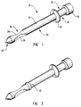
- a preferred design of the connector rod 10 of the present invention includes an elongate shaft 12 that is generally cylindrical or ellipsoidal.
- the connector rod 10 has a penetrating segment 16 at one end, an impact segment 18 at the opposite end, and a mesial segment 20 disposed between the penetrating segment 16 and the impact segment 18.
- the mesial segment 20 essentially comprises the middle section of the elongate shaft 12 although appropriate accessories or other design features could be included therein to provide further functionality.
- a pointed tip 22 At the end of the penetrating segment 16 distal to the mesial segment 20 is a pointed tip 22.
- the pointed tip 22 has a generally conical shape as shown in Figure 1, it can be of any shape so long as it generally ends in a tip having a substantially reduced diameter relative to the diameter of the elongate shaft 12.
- the pointed tip 22 facilitates entry of the connector rod 10 through an insulating layer and a first layer of fresh, unhardened structural material, as set forth more fully below.
- the penetrating segment 16 further includes one or more recesses 24 disposed between the mesial segment 20 and the area of the penetrating segment 16 near the pointed tip 22.
- the penetrating segment 16 is intended to substantially penetrate and be anchored within a first structural layer.
- the recessed portions 24 greatly aid in the anchoring and securing of the penetrating segment 16 within the first structural layer.
- the mesial segment 20 which is generally of uniform shape, and may be cylindrical or may have a cross-section of, e.g. , an ellipse or cruciform.
- a flange 26 or other ridge Near or at the end of the mesial segment 20 distal to the penetrating segment 16 is a flange 26 or other ridge which acts as a means for orienting the connector rod 10 within an insulating layer stacked together with a first structural layer.
- the mesial segment 20 is intended to occupy, in a close-fitting manner, a hole drilled within the insulating layer or formed by the piercing effect of the pointed tip 22 of the penetrating segment 16 when the connector rod 10 is inserted through the insulating layer and into a first structural layer of yet unhardened material.
- the length of the mesial segment is generally equal to the thickness of the insulating layer.
- the flange 26 or other ridge aids in the placement of the connector rod 10 at the proper depth through the insulating layer and first structural layer.
- the flange 26 should be oriented at an angle relative to the elongate shaft 12 which corresponds to the desired angle of orientation of the connector rod 10 through the composite wall structure. If, for example, the connector is intended to be oriented perpendicular to the surface of the insulating layer ( Figure 6A), the flange 26 would preferably be oriented orthogonally to the surface of the elongate shaft 12. However, the flange may be offset at any appropriate angle.
- the impact segment begins at or near the flange 26 or other ridge along the elongate shaft 12 and terminates at an enlarged head 28 disposed at an end of the impact segment 18 distal to the mesial segment 20.
- the ridge or flange 26 is said to be at or near (or proximal to) the intersection of the mesial segment 20 and impact segment 18 because of the interplay between the definitions of the three connector rod segments and the layers of the composite wall structure into which the segments will be imbedded, as well as the accuracy of placement of the connector rods within the layers and the thickness of the ridge or flange 26.
- One of the purposes of the enlarged head 28 is to receive an impact force, such as from a hammer or mallet, or to facilitate the gripping of the connector rod 10 during its insertion through an insulating layer and a first structural layer.
- the enlarged head 28 also functions to prevent a second structural layer that is formed round the impact segment 18 from pulling away from the first structural layer and insulating layer.
- the flange 26 or other ridge prevents the second structural layer from collapsing toward the first structural layer.
- the enlarged head 28 and flange 26 or other ridge define a pseudo-recessed portion 30 within the portion of the elongate shaft 12 therebetween, although the portion of the elongate shaft 12 between the enlarged head 28 and flange 26 may have the same diameter as the rest of the elongate shaft 12 (excluding recesses 24). Because of the ease in which the connector rods of the present invention may be injection molded, the pointed tip 22, the recesses 24, the flange 26, and the enlarged head 28 can be quickly and easily formed within the connector rod 10 in a single molding step.
- a freshly demolded connector rod may, if desired, be structurally altered such as by curving or bending the connector rod while still in an unhardened condition.
- a cammed ridge 32 can be incorporated along the elongate shaft 12 proximal to the intersection between the penetrating segment 16 and the mesial segment 20.
- the purpose of the cammed ridge 32 is to provide means for locking the connector rod in place once it has been fully inserted through the insulating layer up to the flange 26.
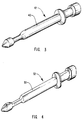
- Figure 3 shows another alternative embodiment that has substantially the same structural features as the connector rod 10 shown in Figure 1, except that the elongate shaft 40 and other features of the connector rod 42 have a slightly elliptical cross-section rather than being cylindrical.
- the connector rod 40 functions in essentially the same way as the connector rod 10 of Figure 1.
- the shape of the recesses are different in this embodiment, they perform essentially the same anchoring function as the recesses illustrated in Figures 1 and 2.
- the shape or depth of the recess or recesses is relatively unimportant so long as the recesses provide adequate means for anchoring the penetrating segment within a first structural layer.
- Figure 4 shows another embodiment of a connector rod of the present invention similar to that shown in Figure 3, except that the elongate shaft 50 of connector rod 52 has an even more exaggerated elliptical cross-section compared to the connector rod 40 of Figure 3.
- the cross-sectional shape of the elongate shaft and other design features is less important than the functional features themselves.
- the actual cross-sectional shape may be selected to correspond to the particular design and performance criteria of the composite wall structure to be manufactured. Because the cross-section of the connector rod of Figure 4 is elliptoidal, the pointed tip is more scalloped than conical.
- Figure 5 illustrates yet another embodiment of the present invention in which the elongate shalt 60 of the connector rod 62 has a generally cruciform cross-section. Within the spaces defined by the fins of the cruciform structure are ridges 64, which aid in the anchoring of the connector rod 62 within a first structural layer. As before, a flange 66 and an enlarged head 68 help to anchor the connector rod 62 within a second structural layer.
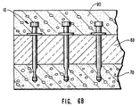
- Figure 6A shows an integral connector rod 10 placed within a front elevational cross-section view of a first structural layer 70 and an insulating layer 80.
- a first layer of a structural material is poured into an appropriate form.
- the first structural layer 70 will be a rectangular slab, although it may also include other design, ornamental or structural features. The only limitation is that it have a thickness or depth great enough to give the structural layer adequate strength and also the ability to firmly anchor the penetrating segment 16 of a connector rod 10 placed therein.
- the first structural layer 70 may comprise any suitable material which can flow when initially cast and then harden to form a generally rigid, structural layer.
- the first structural layer 70 comprises a concrete material including a hydraulic cement binder, water, an aggregate material and other appropriate admixtures. Concrete is preferred because of its low cost, high strength and ease of casting compared to other materials. Nevertheless, any appropriate structural material may be used, such as high strength polymers, resins or other materials which can flow when cast and later be hardened.
- an insulating layer 80 is placed adjacent to the exposed side of the first structural layer 70.
- the insulating layer may include any appropriate insulating material, such as polystyrene foam, fiberglass, aerogel, xerogel, xonotlite, seagel, polyisocyanate foam, polyurethane foam, urea-formaldehyde foam, and low density, highly insulating cementitious materials.
- insulating materials are given only by way of example, not by limitation.
- the insulating layer 80 preferably includes a plurality of holes drilled or punched therethrough, through which the connector rod 10 of the present invention will be inserted.
- a connector rod 10 is inserted through each of the holes within the insulating layer 80 and also through the first structural layer 70 until the flange 26 prevents further penetration.
- the penetrating segment 16 ( Figure 1) will substantially reside within the first structural layer 70, while the mesial segment 20 will substantially occupy the hole or space within the insulating layer 80 ( Figure 6A). Because of the piercing effect of the pointed tip 22 of the connector rod 10, it may be possible to drill holes having a substantially smaller diameter compared to the diameter of the elongate shaft 12 of the connector rod 10. In some cases, no holes will be required at all.
- a second layer of structural material is poured over the surface of the insulating layer 80 to form the second structural layer 90, as shown in Figure 6B.
- the second structural layer 90 may also comprise any appropriate material that will initially flow and then harden to form a substantially rigid structural wall. Nevertheless, concrete is preferred due to its low cost, high strength and ease of formation.
- the second structural layer 90 will generally be a rectangular slab, it may also include other designs, structural or ornamental features.
- the thickness or depth of the second structural layer 90 should be such that it completely, or at least substantially, engulfs the enlarged head 28 of the connector rod 10, thereby providing an adequate anchoring effect of the connector rod 10 within the second structural layer 90.
- the flange 26 also aids in preventing the hardened second structural layer 90 from collapsing against the first structural layer 70.
- a second insulating layer over the yet unhardened second structural layer, followed by the insertion of additional connector rods through the second insulation layer and second structural layer. Thereafter, a third structural layer will be cast over the surface of the second insulating layer as before. Because of the simplicity of molding the connector rods of the present invention, an adapted connector rod could be molded that would connect all three structural layers together.
- the various connector rods described herein were used in experimental composite wall structures and were found to have more than adequate shear strength to hold together the three layers of the composite wall structures that were tested. In fact, in all cases when a stress strong enough to cause a failure of the composite wall structure was applied, it was the concrete structural layer that failed in each instance. The connector rods were left intact.
- the present invention provides improved designs and methods for manufacturing highly insulative composite wall connectors.
- the present invention also provides improved designs and methods for making improved connector rods that can be molded in a single step, and yet provide means for anchoring the connector rod within the structural layers, while also providing means for positioning the connector within the insulating layer during the formation of the composite wall structure.
- the present invention provides connector rods that can be integrally molded in one step without the need to separately mold an elongate connector shaft having means for retaining the shaft within the outer structural layers, and a central sleeve portion having a flange and enlarged central diameter for positioning the connector within the insulating layer.
- the present invention provides improved connector rods that have means for facilitating their penetration through an insulating layer and a first of two structural layers during the formation of the composite wall structure.
- the present invention provides improved connectors having means for receiving an impact such as from a hammer or mallet, or to aid in gripping the connector, and thereby facilitate the penetration of the connector rods through the insulating layer and the first structural layer.
Landscapes
- Engineering & Computer Science (AREA)
- General Engineering & Computer Science (AREA)
- Mechanical Engineering (AREA)
- Structural Engineering (AREA)
- Architecture (AREA)
- Civil Engineering (AREA)
- Chemical & Material Sciences (AREA)
- Ceramic Engineering (AREA)
- Joining Of Building Structures In Genera (AREA)
- Insulating Bodies (AREA)
- Flanged Joints, Insulating Joints, And Other Joints (AREA)
- Building Environments (AREA)
- Panels For Use In Building Construction (AREA)
- Reinforcement Elements For Buildings (AREA)
- Manufacturing Of Tubular Articles Or Embedded Moulded Articles (AREA)
- Casting Or Compression Moulding Of Plastics Or The Like (AREA)
- Connector Housings Or Holding Contact Members (AREA)
Claims (19)
- Hochisolierender zusammengesetzter Wandaufbau mit einer ersten tragenden Schicht (70), die ein hochfestes Material umfaßt, einer zweiten tragenden Schicht (90), die ein hochfestes Material umfaßt, und einer Isolierschicht (80), die ein Material mit einem hohen Wärmewiderstand umfaßt, das zwischen der ersten und der zweiten tragenden Schicht angeordnet ist, wobei die erste tragende Schicht, die zweite tragende Schicht und die Isolierschicht mittels zumindest eines Verbinders (10) mit hohem Wärmewiderstand zusammengehalten werden, wobei der Verbinder umfaßt:einen verlängerten Schaft (12) mit einem Eindringabschnitt (16), der innerhalb der ersten tragenden Schicht angeordnet wird, einem Schlagabschnitt (18), der innerhalb der zweiten tragenden Schicht angeordnet wird, und einem Mittelabschnitt (20), der innerhalb der Isolierschicht angeordnet wird;eine im wesentlichen zugespitzte Spitze (22) an einem Ende des Eindringabschnitts entfernt zum Mittenabschnitt zum Durchdringen der Isolierschicht und der ersten tragenden Schicht, während diese sich in einem unausgehärteten Zustand während der Herstellung der zusammengesetzten Wand befindet;einen vergrößerten Kopf (28) an einem Ende des Schlagabschnitts entfernt zum Mittenabschnitt;Mittel (26) zum Ausrichten des Verbindungsstabs innerhalb des Isoliermaterials in einer vorbestimmten Tiefe;erste Verankerungsmittel (24) im Eindringabschnitt zum Verankern des Eindringabschnitts innerhalb der ersten tragenden Schicht; undzweite Verankerungsmittel (30) im Schlagabschnitt zum Verankern des Schlagabschnitts innerhalb der zweiten tragenden Schicht.
- Isolierender zusammengesetzter Wandaufbau nach Anspruch 1, wobei das Mittel zum Ausrichten des Verbinders innerhalb des Isoliermaterials einen Flansch (26) umfaßt, der auf einer Oberfläche des verlängerten Schafts nahe dem Übergang zwischen dem Mittenabschnitt und dem Schlagabschnitt angeordnet ist.
- Isolierender zusammengesetzter Wandaufbau nach Anspruch 2, wobei der Flansch in einem Winkel relativ zur Oberfläche des verlängerten Schafts entsprechend dem gewünschten Winkel der Ausrichtung des Verbinders innerhalb des zusammengesetzten Wandaufbaus ausgerichtet ist.
- Isolierender zusammengesetzter Wandaufbau nach Anspruch 1, wobei das erste Verankerungsmittel einen oder mehrere vertiefte Bereiche (24) innerhalb des verlängerten Schafts umfaßt, die zwischen dem Mittenabschnitt und der zugespitzten Spitze angeordnet sind.
- Isolierender zusammengesetzter Wandaufbau nach Anspruch 2, wobei das zweite Verankerungsmittel den vergrößerten Kopf in Verbindung mit dem Flansch umfaßt.
- Isolierender zusammengesetzter Wandaufbau nach Anspruch 1, wobei der Verbinder ein Kunststoffmaterial umfaßt, das aus der Gruppe ausgewählt wird, die Polykarbonate, Harz auf Epoxybasis, Polykarbonat-Polybutylenteraphtalatlegierungen, hochfeste Harze, spritzgießbare Kunststoffmaterialien und Thermoplaste umfaßt.
- Isolierender zusammengesetzter Wandaufbau nach Anspruch 6, wobei der Verbinder aus dem Kunststoffmaterial in einem einzigen Spritzgußschritt stranggepreßt wird.
- Isolierender zusammengesetzter Wandaufbau nach Anspruch 7, wobei das Kunststoffmaterial mit nicht endlosen Fasern getränkt ist.
- Isolierender zusammengesetzter Wandaufbau nach Anspruch 8, wobei die Fasern aus einer Gruppe ausgewählt werden, die Glasfasern, Karbonfasern, Borfasern, keramische Fasern und Mischungen derselben umfaßt.
- Isolierender zusammengesetzter Wandaufbau nach Anspruch 1, wobei der Verbinder des weiteren Mittel (32) zum Verklemmen des Verbinders vor Ort in der Isolierschicht umfaßt.
- Isolierender zusammengesetzter Wandaufbau nach Anspruch 1, wobei die Isolierschicht ein Isoliermaterial umfaßt, das aus der Gruppe, die Polystyrolschaum und Fiberglas umfaßt, ausgewählt wird.
- Isolierender zusammengesetzter Wandaufbau nach Anspruch 1, wobei zumindest eine der ersten und zweiten tragenden Schicht ein Betonmaterial umfaßt.
- Isolierender zusammengesetzter Wandaufbau nach Anspruch 2, wobei das erste Verankerungsmittel einen oder mehrere vertiefte Bereiche (24) innerhalb des verlängerten Schafts umfaßt, die zwischen dem Mittenabschnitt und der zugespitzten Spitze angeordnet sind, und der vergrößerte Kopf im Verankern des Schlagabschnitts in der zweiten tragenden Schicht hilft.
- Isolierender zusammengesetzter Wandaufbau nach Anspruch 13, wobei der Verbinder ein Kunststoffmaterial umfaßt, das aus der Gruppe ausgewählt wird, die Polykarbonate, Harz auf Epoxybasis, Legierungen aus Polykarbonat-Polybutylenteraphtalaten, hochfeste Harze, spritzgießbare Kunststoffmaterialien und Thermoplaste umfaßt.
- Isolierender zusammengesetzter Wandaufbau nach Anspruch 14, wobei der Verbinder aus dem Kunststoffmaterial in einem einzigen Spritzgußschritt stranggepreßt wird.
- Isolierender zusammengesetzter Wandaufbau nach jedem der vorangehenden Ansprüche, welcher eine Mehrzahl der Verbinder umfaßt.
- Verfahren zur Herstellung eines hochisolierenden zusammengesetzten Wandaufbaus, der eine erste tragende Schicht (70), eine zweite tragende Schicht (90) und eine Isolierschicht (80), die ein Material mit einem hohen Wärmewiderstand umfaßt, das zwischen der ersten und der zweiten tragenden Schicht angeordnet ist, aufweist, umfassend die Schritte:(A) Schaffen von zumindest einem hochwärmeisolierten Verbinder (10), umfassend:einen verlängerten Schaft (12) mit einem Eindringabschnitt (15), einem Schlagabschnitt (18) und einem Mittelabschnitt (20);eine zugespitzte Spitze (22) an einem Ende des Eindringabschnitts entfernt zum Mittenabschnitt;einen vergrößerten Kopf (28) an einem Ende des Schlagabschnitts entfernt zum Mittenabschnitt;Mittel (26) zum Ausrichten des Verbindungsstabs innerhalb des Isoliermaterials in einer vorbestimmten Tiefe;erste Verankerungsmittel (24), die im Eindringabschnitt angeordnet sind, zum Verankern des Eindringabschnitts innerhalb der ersten tragenden Schicht;zweite Verankerungsmittel (30), die im Schlagabschnitt angeordnet sind, zum Verankern des Schlagabschnitts innerhalb der zweiten tragenden Schicht;(B) Ausbilden einer ersten Schicht, die ein nicht ausgehärtetes tragendes Material umfaßt;(C) Anordnen der Isolierschicht auf der Oberfläche der ersten nicht ausgehärteten Schicht;(D) Einführen von zumindest einem Verbinder, so daß der Eindringabschnitt durch die Isolierschicht und in die erste nicht ausgehärtete Schicht eindringt, damit der Mittenabschnitt innerhalb der Isolierschicht angeordnet ist, und so daß der Schlagabschnitt sich von der offenliegenden Oberfläche der Isolierschicht aus erstreckt;(E) Ausbilden einer zweiten Schicht, die ein nicht ausgehärtetes tragendes Material auf der offenliegenden Oberfläche der Isolierschicht umfaßt, so daß der Schlagabschnitt in der zweiten Schicht angeordnet ist; und(F) Aushärten der ersten Schicht in eine erste tragende Schicht und des Aushärtens der zweiten Schicht in eine zweite tragende Schicht, wodurch der zusammengesetzte Wandaufbau ausgebildet wird.
- Verfahren nach Anspruch 17, wobei der Verbinder ein Kunststoffmaterial umfaßt, das aus der Gruppe ausgewählt wird, die Polykarbonate, Harz auf Epoxybasis, Polykarbonat-Polybutylenteraphtalatlegierungen, hochteste Harze, spritzgießbare Kunststoffmaterialien und Thermoplaste umfaßt.
- Verfahren nach Anspruch 18, wobei der Verbinder aus dem Kunststoffmateriai in einem einzigen Spritzgußschritt stranggepreßt wird.
Applications Claiming Priority (3)
| Application Number | Priority Date | Filing Date | Title |
|---|---|---|---|
| US08/225,910 US5519973A (en) | 1993-08-17 | 1994-04-08 | Highly insulative connector rods and methods for their manufacture and use in highly insulated composite walls |
| US225910 | 1994-04-08 | ||
| PCT/US1995/003842 WO1995027835A1 (en) | 1994-04-08 | 1995-03-28 | Highly insulative connector rods and methods for their manufacture and use in highly insulated composite walls |
Publications (3)
| Publication Number | Publication Date |
|---|---|
| EP0754265A1 EP0754265A1 (de) | 1997-01-22 |
| EP0754265A4 EP0754265A4 (de) | 1997-08-06 |
| EP0754265B1 true EP0754265B1 (de) | 2000-05-10 |
Family
ID=22846781
Family Applications (1)
| Application Number | Title | Priority Date | Filing Date |
|---|---|---|---|
| EP95914923A Expired - Lifetime EP0754265B1 (de) | 1994-04-08 | 1995-03-28 | Hochisolierende verbindungsstäbe und verfahren zu ihrer herstellung und ihrer anwendung in hochisolierten zusammengesetzten wänden |
Country Status (10)
| Country | Link |
|---|---|
| US (4) | US5519973A (de) |
| EP (1) | EP0754265B1 (de) |
| JP (1) | JP3604144B2 (de) |
| CN (1) | CN1116488C (de) |
| AT (1) | ATE192812T1 (de) |
| AU (1) | AU686367B2 (de) |
| CA (1) | CA2187284C (de) |
| DE (1) | DE69516864T2 (de) |
| ES (1) | ES2147850T3 (de) |
| WO (1) | WO1995027835A1 (de) |
Cited By (1)
| Publication number | Priority date | Publication date | Assignee | Title |
|---|---|---|---|---|
| CN101949178A (zh) * | 2010-09-17 | 2011-01-19 | 黑龙江宇辉新型建筑材料有限公司 | 用于预制混凝土墙体的高强度预埋连接断热件 |
Families Citing this family (87)
| Publication number | Priority date | Publication date | Assignee | Title |
|---|---|---|---|---|
| JPH0849318A (ja) * | 1994-07-26 | 1996-02-20 | Thermomass Technologies Inc | 複合断熱壁及びその製造方法 |
| US6116836A (en) * | 1994-07-26 | 2000-09-12 | Composite Technologies Corporation | Connector for composite insulated wall and method for making the wall |
| US6412243B1 (en) | 1997-04-30 | 2002-07-02 | Franklin S. Sutelan | Ultra-lite modular composite building system |
| US6018918A (en) * | 1997-10-16 | 2000-02-01 | Composite Technologies Corporation | Wall panel with vapor barriers |
| US6202375B1 (en) * | 1997-10-28 | 2001-03-20 | Rolf Otto Kleinschmidt | Method for concrete building system using composite panels with highly insulative plastic connector |
| US5996297A (en) * | 1998-02-04 | 1999-12-07 | H.K. Composites, Inc. | Connectors and brackets used in making insulated composite wall structures |
| US6138981A (en) * | 1998-08-03 | 2000-10-31 | H.K. Composites, Inc. | Insulating connectors used to retain forms during the manufacture of composite wall structures |
| CA2342888A1 (en) | 1998-09-02 | 2000-03-09 | Chris Andros | Device and method for connecting concrete plies in pre-cast concrete wall and ceiling panels |
| US6263638B1 (en) | 1999-06-17 | 2001-07-24 | Composite Technologies Corporation | Insulated integral concrete wall forming system |
| US6711862B1 (en) | 2001-06-07 | 2004-03-30 | Composite Technologies, Corporation | Dry-cast hollowcore concrete sandwich panels |
| US6851233B2 (en) * | 2001-09-15 | 2005-02-08 | Richard Morgenstern | Cast log structure |
| US7444786B2 (en) * | 2001-09-15 | 2008-11-04 | Concrete Log Systems, Inc. | Cast log structure |
| DE10147409B4 (de) * | 2001-09-26 | 2011-01-20 | Hochtief Fertigteilbau Gmbh | Wärmeisolierendes, tragfähiges Bauelement und Verfahren zu seiner Herstellung |
| US8365501B2 (en) | 2001-12-26 | 2013-02-05 | Composite Technologies Corporation | Wide-body connector for concrete sandwich walls |
| US8449555B1 (en) * | 2002-03-27 | 2013-05-28 | Terry L. Ray | Pedicle probe |
| US7014407B2 (en) * | 2002-05-23 | 2006-03-21 | Stanley Fastening Systems, L.P. | Full-round, offset-head nail |
| US7266931B2 (en) * | 2002-07-22 | 2007-09-11 | Composite Technologies Corporation | Concrete sandwich wall panels and a connector system for use therein |
| US6895720B2 (en) * | 2002-09-25 | 2005-05-24 | Hk Marketing Lc | High strength composite wall connectors having tapered or pointed ends |
| US20040055247A1 (en) * | 2002-09-25 | 2004-03-25 | Keith David O. | High strength composite wall connectors having a tapered edge |
| RU2249085C2 (ru) * | 2002-12-03 | 2005-03-27 | Общество С Ограниченной Ответственностью "Бийский Завод Стеклопластиков" | Стержень для армирования бетонных конструкций и установка для его изготовления |
| DE10324760A1 (de) * | 2003-05-26 | 2004-12-30 | Construction Systems Marketing Gmbh | Wandbauelement, Verfahren zur Herstellung eines Wandbauelements und ein Verbindungsmittel für ein Wandbauelement |
| US6854229B2 (en) | 2003-05-29 | 2005-02-15 | H.K. Marketing Llc | Form tie sleeves for composite action insulated concrete sandwich walls |
| US7251917B2 (en) * | 2003-06-11 | 2007-08-07 | Sava Cvek | Methods and arrangements for securing fabric |
| US20060032166A1 (en) * | 2004-08-10 | 2006-02-16 | Devalapura Ravi K | High strength composite wall panel system |
| US7861479B2 (en) | 2005-01-14 | 2011-01-04 | Airlite Plastics, Co. | Insulated foam panel forms |
| US20060226406A1 (en) * | 2005-04-02 | 2006-10-12 | Alabama Metal Industries Corporation | Non-conductive fencing |
| AU2006311856A1 (en) * | 2005-11-02 | 2007-05-18 | Richard M. Grabowski | Self-forming structures |
| US20070122252A1 (en) * | 2005-11-28 | 2007-05-31 | Bosacco Stephen A | Fastener for sheet material |
| US7562499B2 (en) * | 2006-01-13 | 2009-07-21 | HC Bridge Company, LLC | Hybrid composite beam system |
| US7895799B2 (en) * | 2006-01-13 | 2011-03-01 | HC Bridge Company, LLC | Hybrid composite beam and beam system |
| US7810293B2 (en) * | 2006-08-15 | 2010-10-12 | Gibbar James H | Multiple layer polymer foam and concrete system for forming concrete walls, panels, floors, and decks |
| DE102006049335A1 (de) * | 2006-10-19 | 2008-04-24 | Fischerwerke Artur Fischer Gmbh & Co. Kg | Anker, Befestigungsanordnung und Verfahren zur Erstellung der Befestigungsanordnung |
| ITMI20060361U1 (it) * | 2006-10-20 | 2008-04-21 | Edilmatic S R L | Sistema di collegamento per pannelli isolanti |
| USD564345S1 (en) * | 2006-12-12 | 2008-03-18 | Camilo Prada | Stop nail |
| EP2045059A3 (de) * | 2007-01-25 | 2010-10-06 | Rudus Oy | Bauelement und sein Herstellungsverfahren |
| CN101054283B (zh) * | 2007-03-30 | 2010-06-30 | 巢启 | 一种建筑保温泡沫板连接件及用途 |
| US20100319295A1 (en) * | 2008-03-12 | 2010-12-23 | Nelson Steven J | Foam-concrete rebar tie |
| US20090229214A1 (en) * | 2008-03-12 | 2009-09-17 | Nelson Steven J | Foam-concrete rebar tie |
| CN201246379Y (zh) * | 2008-07-07 | 2009-05-27 | 鸿富锦精密工业(深圳)有限公司 | 紧固件 |
| AT508406B1 (de) * | 2009-06-16 | 2012-01-15 | Franz Oberndorfer Gmbh & Co Kg | Halbfertigteil zur herstellung von wänden von bauwerken sowie verfahren zu dessen herstellung |
| DE102011014063B4 (de) * | 2011-03-16 | 2015-07-02 | Syspro-Gruppe Betonbauteile E.V. | Wandbauelement |
| EP2514883A1 (de) | 2011-04-20 | 2012-10-24 | Isola Belgium | Vorgefertigtes isoliertes Wandelement für ein Gebäude und Verfahren zu seiner Herstellung |
| DE102011077657A1 (de) | 2011-06-16 | 2012-12-20 | Adolf Würth GmbH & Co. KG | Dämmstoffhalter |
| US8756890B2 (en) * | 2011-09-28 | 2014-06-24 | Romeo Ilarian Ciuperca | Insulated concrete form and method of using same |
| US8555584B2 (en) * | 2011-09-28 | 2013-10-15 | Romeo Ilarian Ciuperca | Precast concrete structures, precast tilt-up concrete structures and methods of making same |
| CA2793668A1 (en) | 2011-10-31 | 2013-04-30 | Bradley J. Crosby | An apparatus and method for construction of structures utilizing insulated concrete forms |
| CA2801735C (en) | 2012-01-13 | 2019-08-06 | Bradley J. Crosby | An apparatus and method for construction of structures utilizing insulated concrete forms |
| US8881480B1 (en) * | 2012-05-25 | 2014-11-11 | Phase Change Energy Solutions, Inc. | Construction assembly and method |
| USD713975S1 (en) | 2012-07-30 | 2014-09-23 | Airlite Plastics Co. | Insulative insert for insulated concrete form |
| US9080587B1 (en) * | 2012-10-05 | 2015-07-14 | Michael C. Smith | Spike for securing a flexible member to earth strata |
| US8844227B1 (en) | 2013-03-15 | 2014-09-30 | Romeo Ilarian Ciuperca | High performance, reinforced insulated precast concrete and tilt-up concrete structures and methods of making same |
| CN104110082B (zh) * | 2013-04-16 | 2016-03-30 | 山东汇星科技开发有限公司 | 外模内置复合保温板现浇砼一体化墙体结构及其制造方法 |
| US20150071734A1 (en) * | 2013-09-06 | 2015-03-12 | Herman Vallejo | self-wedging concrete nail |
| US9493946B2 (en) * | 2013-12-13 | 2016-11-15 | Iconx, Llc | Tie system for insulated concrete panels |
| ES2906092T3 (es) * | 2014-04-04 | 2022-04-13 | Dieterle Gbr | Cobertura para puente y unidad de fijación para fijar una cobertura para puente |
| CN104074305B (zh) * | 2014-06-13 | 2016-08-24 | 广东河源莲田建筑工业化制造有限公司 | 一种自保温装饰一体化多功能轻质混凝土复合板块及幕墙 |
| CN104060716A (zh) * | 2014-06-24 | 2014-09-24 | 山东万斯达建筑工业化研究院有限公司 | 一种夹心复合墙板连接棒 |
| US9303404B2 (en) * | 2014-07-09 | 2016-04-05 | Lehigh University | Insulated structural panel connector |
| USD807157S1 (en) * | 2014-12-09 | 2018-01-09 | Zurn Industries, Llc | Fastener |
| USD764266S1 (en) | 2015-06-26 | 2016-08-23 | Hk Marketing Lc | Composite action tie |
| US10000928B2 (en) | 2015-08-24 | 2018-06-19 | Hk Marketing Lc | Tie for composite wall system that is both screwable and axially pushable |
| US10634371B2 (en) * | 2015-11-20 | 2020-04-28 | Stasis Energy Group, Llc | System for energy consumption reduction and cost savings in a building |
| GB2548840A (en) * | 2016-03-29 | 2017-10-04 | Staponkiene Natalija | Thermal block and methods of construction |
| US10011988B2 (en) | 2016-05-11 | 2018-07-03 | Joel Foderberg | System for insulated concrete composite wall panels |
| AT518959B1 (de) * | 2016-08-04 | 2018-12-15 | Redlberger Alfred | Verfahren zur Herstellung von Fertigbauteilen für Gebäude |
| CN106284744B (zh) * | 2016-10-11 | 2018-08-17 | 哈尔滨鸿盛房屋节能体系研发中心 | 大模块保温墙体结构 |
| US10113323B2 (en) * | 2016-10-31 | 2018-10-30 | Stego Industries, LLC | Concrete forming stake apparatus |
| CA2985438A1 (en) | 2016-11-14 | 2018-05-14 | Airlite Plastics Co. | Concrete form with removable sidewall |
| CN106677421A (zh) * | 2016-12-29 | 2017-05-17 | 中民筑友科技投资有限公司 | 预制混凝土构件及其制备方法 |
| WO2018145053A1 (en) * | 2017-02-06 | 2018-08-09 | Yin Hongxi | Tie shear connector for wall panel construction and method thereof |
| USD846976S1 (en) * | 2017-02-24 | 2019-04-30 | Magmatech Ltd | Sandwich panel anchor |
| USD856121S1 (en) | 2018-01-29 | 2019-08-13 | Hk Marketing Lc | Composite action tie |
| USD856122S1 (en) | 2018-07-13 | 2019-08-13 | Hk Marketing Lc | Tie |
| US10870988B2 (en) | 2018-01-29 | 2020-12-22 | Hk Marketing Lc | Tie for composite wall system fitting between insulation sheets |
| CN108425474B (zh) * | 2018-04-24 | 2023-08-08 | 中国建筑第八工程局有限公司 | 先装装饰板的预制混凝土墙板及其制作方法 |
| DE102018207761B3 (de) * | 2018-05-17 | 2019-09-26 | Polycare Research Technology Gmbh & Co. Kg | Segment für ein Bauwerk, Verfahren zu dessen Herstellung, Bauwerk und Verfahren zu dessen Herstellung |
| USD880996S1 (en) * | 2018-08-30 | 2020-04-14 | OCM, Inc. | Drill-in concrete form tie |
| CA3061942A1 (en) | 2018-11-19 | 2020-05-19 | Bradley J. Crosby | Concrete form with removable sidewall |
| CN109914607A (zh) * | 2019-03-05 | 2019-06-21 | 上海鹄鸫重工机械有限公司 | 一种建筑构件用自攻钉 |
| USD968199S1 (en) | 2019-04-23 | 2022-11-01 | Hk Marketing Lc | Tie standoff |
| NO345690B1 (en) | 2019-06-12 | 2021-06-14 | Frank Cato Lahti | Wall-building element system and prefabricated basic wall-building element. |
| US11015345B1 (en) | 2020-01-18 | 2021-05-25 | Walter Smith | Concrete wall section |
| FR3107910B1 (fr) * | 2020-03-09 | 2022-04-29 | Josselin Guicherd | Connecteurs pour relier entre elles des première et seconde parois d’un élément préfabriqué. |
| CN111519833B (zh) * | 2020-04-21 | 2021-07-06 | 西安建筑科技大学 | 一种预制夹芯保温墙体 |
| CN113186805B (zh) * | 2021-04-13 | 2022-12-13 | 山东大成钢结构工程有限公司 | 一种装配式桥梁钢结构预制件 |
| DE102021125449A1 (de) | 2021-09-30 | 2023-04-13 | Fixit Trockenmörtel Holding AG | Verfahren zur herstellung eines kerngedämmten betonfertigteils sowie kerngedämmtes betonfertigteil |
| US20240271651A1 (en) * | 2023-02-10 | 2024-08-15 | Jeremy Shaw | Drywall Fastening Button Device |
Family Cites Families (47)
| Publication number | Priority date | Publication date | Assignee | Title |
|---|---|---|---|---|
| US2646929A (en) * | 1953-07-28 | Gourdon | ||
| US937142A (en) * | 1907-02-19 | 1909-10-19 | Charles William Chappelow | Method of producing concrete structures. |
| US2412744A (en) * | 1944-07-24 | 1946-12-17 | Nelson Ted | Insulation stud |
| US2653469A (en) * | 1948-06-12 | 1953-09-29 | Patrick J Callan | Building wall construction |
| US2718138A (en) * | 1948-12-09 | 1955-09-20 | Cable B Jones | Concrete wall interlocking insulation pad |
| US2645929A (en) * | 1948-12-09 | 1953-07-21 | Cable B Jones | Tie bar for insulated concrete walls |
| US2595123A (en) * | 1949-01-21 | 1952-04-29 | Patrick J Callan | Method of constructing buildings |
| US2575079A (en) * | 1949-05-13 | 1951-11-13 | Temple Velocity Equipment Inc | Explosively driven stud with knockoff head portion |
| US2769333A (en) * | 1952-12-15 | 1956-11-06 | George P Reintjes | Wall facing |
| US2775018A (en) * | 1953-04-16 | 1956-12-25 | James A Mclaughlin | Concrete spacer tie rod |
| US3000144A (en) * | 1956-03-07 | 1961-09-19 | Casavan Ind | Composite panels for building constructions |
| US2964821A (en) * | 1956-07-05 | 1960-12-20 | Donald E Meehan | Apparatus for constructing building walls |
| US3131514A (en) * | 1958-01-08 | 1964-05-05 | Siek Metta | Thin precast wall panel construction |
| US3208328A (en) * | 1962-04-11 | 1965-09-28 | John L Myers | Screws |
| US3304676A (en) * | 1964-01-29 | 1967-02-21 | Bird & Son | Siding construction |
| BE794529Q (fr) * | 1966-01-24 | 1973-05-16 | Architectural Res Corp | Panneau decoratif a ame en mousse et procede pour le fabriquer |
| GB1183704A (en) * | 1966-09-12 | 1970-03-11 | Lucas Industries Ltd | A Method of Securing Two Parts in End to End Relationship. |
| US3426494A (en) * | 1967-08-15 | 1969-02-11 | Alfred A Hala | Wall-tie assembly for use in the construction of waterproof walls |
| US3646715A (en) * | 1970-04-06 | 1972-03-07 | Du Pont Canada | Prefabricated building panel |
| DE2024157A1 (de) * | 1970-05-16 | 1971-12-02 | Körner, Manfred, Dipl.-Kfm., 7500 Karlsruhe-Durlach | Mehrschichten-Betonplatte |
| US3701228A (en) * | 1970-07-23 | 1972-10-31 | Frank Taylor | Decorative wall facing |
| DE2120746A1 (de) * | 1971-04-28 | 1972-11-16 | Blum-Bau Kg, 5210 Troisdorf | Fassadenelement |
| US3879908A (en) * | 1971-11-29 | 1975-04-29 | Victor P Weismann | Modular building panel |
| ZA738037B (en) * | 1972-10-30 | 1975-07-30 | Deutsher Pty Ltd | Drill screw |
| US4018023A (en) * | 1974-03-06 | 1977-04-19 | The Carborundum Company | Ceramic elements and insulation assembly including such elements |
| GB1568603A (en) * | 1977-01-15 | 1980-06-04 | Carborundum Co Ltd | Furnace linings |
| DE2715277A1 (de) * | 1977-04-05 | 1978-10-12 | Karl Becher | Sandwich-bauelement sowie damit hergestellte baukonstruktion |
| US4213929A (en) * | 1978-09-22 | 1980-07-22 | Dobson Michael J | Solar collector |
| US4329821A (en) * | 1980-04-30 | 1982-05-18 | Long Robert T | Composite insulated wall |
| US4348847A (en) * | 1980-10-06 | 1982-09-14 | Mod-Lok Industries Ltd. | Spacer extender |
| US4393635A (en) * | 1981-04-30 | 1983-07-19 | Long Robert T | Insulated wall construction apparatus |
| DE3325352A1 (de) * | 1983-07-14 | 1985-02-21 | Fricker, Siegfried, 7135 Wiernsheim | Verbundanker einer schichtverbundplatte zur herstellung von gebaeudewaenden |
| CA1199810A (en) * | 1983-11-15 | 1986-01-28 | Ovila Asselin | Heat insulated tie rod for concrete wall members |
| US4568215A (en) * | 1983-11-21 | 1986-02-04 | Illinois Tool Works Inc. | Laterally adjustable fastening assembly |
| US4973211A (en) * | 1985-04-10 | 1990-11-27 | Star Fasteners International, Inc. | Star fasteners |
| US4702053A (en) * | 1986-06-23 | 1987-10-27 | Hibbard Construction Co. | Composite insulated wall |
| US5031378A (en) * | 1986-12-01 | 1991-07-16 | Engineered Construction Components (America) Inc. | Method of inserting a rivet into a roof structure |
| FR2610375A1 (fr) * | 1987-01-30 | 1988-08-05 | Prospection & Inventions | Tampon de fixation de panneau |
| DE3738471A1 (de) * | 1987-11-12 | 1989-05-24 | Hilti Ag | Befestigungselement zum eintreiben in harte werkstoffe |
| US4829733A (en) * | 1987-12-31 | 1989-05-16 | Thermomass Technology, Inc. | Connecting rod mechanism for an insulated wall construction |
| DE3813245A1 (de) * | 1988-04-20 | 1989-11-02 | Hilti Ag | Befestigungselement mit fuehrungsrondelle |
| AT392330B (de) * | 1989-07-14 | 1991-03-11 | Sfs Stadler Holding Ag | Befestigungselement zur fixierung von isolierbahnen oder -platten auf einem festen unterbau |
| DE3925780A1 (de) * | 1989-08-03 | 1991-02-07 | Gruenzweig & Hartmann | Daemmelement zur bildung einer fertigen sichtseite, insbesondere einer gebaeudedecke, sowie wand mit einem solchen daemmelement und verfahren zur herstellung einer solchen wand |
| US4945700A (en) * | 1989-09-12 | 1990-08-07 | Powell Wayne T | Tool and methodology for patching wallboard |
| US5094057A (en) * | 1990-01-16 | 1992-03-10 | Morris Phillip L | Anchor for simulated marble panels and the like |
| US5057257A (en) * | 1990-02-20 | 1991-10-15 | Quantum Composites, Inc. | Method of transfer molding fiber-reinforced resin bolt products |
| US5011354A (en) * | 1990-02-28 | 1991-04-30 | Brownlee Ritch J | Concrete fastener apparatus |
-
1994
- 1994-04-08 US US08/225,910 patent/US5519973A/en not_active Expired - Lifetime
-
1995
- 1995-03-28 CA CA002187284A patent/CA2187284C/en not_active Expired - Fee Related
- 1995-03-28 AU AU21986/95A patent/AU686367B2/en not_active Ceased
- 1995-03-28 ES ES95914923T patent/ES2147850T3/es not_active Expired - Lifetime
- 1995-03-28 AT AT95914923T patent/ATE192812T1/de not_active IP Right Cessation
- 1995-03-28 EP EP95914923A patent/EP0754265B1/de not_active Expired - Lifetime
- 1995-03-28 JP JP52636295A patent/JP3604144B2/ja not_active Expired - Fee Related
- 1995-03-28 CN CN95192498A patent/CN1116488C/zh not_active Expired - Fee Related
- 1995-03-28 DE DE69516864T patent/DE69516864T2/de not_active Expired - Fee Related
- 1995-03-28 WO PCT/US1995/003842 patent/WO1995027835A1/en not_active Ceased
- 1995-09-11 US US08/526,805 patent/US5830399A/en not_active Expired - Fee Related
-
1997
- 1997-09-24 US US08/936,869 patent/US5987834A/en not_active Expired - Lifetime
-
1999
- 1999-10-12 US US09/417,158 patent/US6112491A/en not_active Expired - Lifetime
Cited By (1)
| Publication number | Priority date | Publication date | Assignee | Title |
|---|---|---|---|---|
| CN101949178A (zh) * | 2010-09-17 | 2011-01-19 | 黑龙江宇辉新型建筑材料有限公司 | 用于预制混凝土墙体的高强度预埋连接断热件 |
Also Published As
| Publication number | Publication date |
|---|---|
| EP0754265A1 (de) | 1997-01-22 |
| US5987834A (en) | 1999-11-23 |
| WO1995027835A1 (en) | 1995-10-19 |
| CA2187284C (en) | 1999-08-31 |
| JP3604144B2 (ja) | 2004-12-22 |
| DE69516864D1 (de) | 2000-06-15 |
| CA2187284A1 (en) | 1995-10-19 |
| US5830399A (en) | 1998-11-03 |
| CN1147283A (zh) | 1997-04-09 |
| EP0754265A4 (de) | 1997-08-06 |
| AU2198695A (en) | 1995-10-30 |
| ATE192812T1 (de) | 2000-05-15 |
| AU686367B2 (en) | 1998-02-05 |
| DE69516864T2 (de) | 2000-10-19 |
| CN1116488C (zh) | 2003-07-30 |
| ES2147850T3 (es) | 2000-10-01 |
| JPH09511803A (ja) | 1997-11-25 |
| US5519973A (en) | 1996-05-28 |
| US6112491A (en) | 2000-09-05 |
Similar Documents
| Publication | Publication Date | Title |
|---|---|---|
| EP0754265B1 (de) | Hochisolierende verbindungsstäbe und verfahren zu ihrer herstellung und ihrer anwendung in hochisolierten zusammengesetzten wänden | |
| US5606832A (en) | Connectors used in making highly insulated composite wall structures | |
| US5673525A (en) | Insulating connector rods used in making highly insulated composite wall structures | |
| US5809723A (en) | Multi-prong connectors used in making highly insulated composite wall structures | |
| US5996297A (en) | Connectors and brackets used in making insulated composite wall structures | |
| US8397455B2 (en) | High strength composite wall panel system | |
| US6138981A (en) | Insulating connectors used to retain forms during the manufacture of composite wall structures | |
| US6854229B2 (en) | Form tie sleeves for composite action insulated concrete sandwich walls | |
| CA1310202C (en) | Connecting rod mechanism for an insulated wall construction | |
| CA2442207C (en) | High strength composite wall connectors having tapered or pointed ends | |
| WO2002098621A2 (en) | Dry-cast hollowcore concrete sandwich panels | |
| EP0954652B1 (de) | Isolierte verbindungskabel zur anwendung bei der herstellung hochisolierter zusammengesetzter wandkonstruktionen | |
| US20040055247A1 (en) | High strength composite wall connectors having a tapered edge | |
| MXPA96004664A (en) | Summary connector rods and methods for its manufacture and use in compound walls | |
| US20040050004A1 (en) | Insulated cast concrete wall system and insulation tie | |
| KR20050033136A (ko) | 건축물 내, 외장용 인조석 판재와 그의 제조 및 시공방법 | |
| KR20050074714A (ko) | 건축물 내, 외장용 인조석 판재 | |
| CN118498574A (zh) | 结构一体化保温装饰板的安装结构及其施工方法 |
Legal Events
| Date | Code | Title | Description |
|---|---|---|---|
| PUAI | Public reference made under article 153(3) epc to a published international application that has entered the european phase |
Free format text: ORIGINAL CODE: 0009012 |
|
| 17P | Request for examination filed |
Effective date: 19961106 |
|
| AK | Designated contracting states |
Kind code of ref document: A1 Designated state(s): AT BE CH DE DK ES FR GB GR IE IT LI NL PT SE |
|
| A4 | Supplementary search report drawn up and despatched |
Effective date: 19970619 |
|
| AK | Designated contracting states |
Kind code of ref document: A4 Designated state(s): AT BE CH DE DK ES FR GB GR IE IT LI NL PT SE |
|
| 17Q | First examination report despatched |
Effective date: 19980210 |
|
| GRAG | Despatch of communication of intention to grant |
Free format text: ORIGINAL CODE: EPIDOS AGRA |
|
| GRAG | Despatch of communication of intention to grant |
Free format text: ORIGINAL CODE: EPIDOS AGRA |
|
| GRAH | Despatch of communication of intention to grant a patent |
Free format text: ORIGINAL CODE: EPIDOS IGRA |
|
| GRAH | Despatch of communication of intention to grant a patent |
Free format text: ORIGINAL CODE: EPIDOS IGRA |
|
| GRAA | (expected) grant |
Free format text: ORIGINAL CODE: 0009210 |
|
| AK | Designated contracting states |
Kind code of ref document: B1 Designated state(s): AT BE CH DE DK ES FR GB GR IE IT LI NL PT SE |
|
| PG25 | Lapsed in a contracting state [announced via postgrant information from national office to epo] |
Ref country code: NL Free format text: LAPSE BECAUSE OF FAILURE TO SUBMIT A TRANSLATION OF THE DESCRIPTION OR TO PAY THE FEE WITHIN THE PRESCRIBED TIME-LIMIT Effective date: 20000510 Ref country code: IT Free format text: LAPSE BECAUSE OF FAILURE TO SUBMIT A TRANSLATION OF THE DESCRIPTION OR TO PAY THE FEE WITHIN THE PRE;WARNING: LAPSES OF ITALIAN PATENTS WITH EFFECTIVE DATE BEFORE 2007 MAY HAVE OCCURRED AT ANY TIME BEFORE 2007. THE CORRECT EFFECTIVE DATE MAY BE DIFFERENT FROM THE ONE RECORDED.SCRIBED TIME-LIMIT Effective date: 20000510 Ref country code: BE Free format text: LAPSE BECAUSE OF FAILURE TO SUBMIT A TRANSLATION OF THE DESCRIPTION OR TO PAY THE FEE WITHIN THE PRESCRIBED TIME-LIMIT Effective date: 20000510 Ref country code: AT Free format text: LAPSE BECAUSE OF FAILURE TO SUBMIT A TRANSLATION OF THE DESCRIPTION OR TO PAY THE FEE WITHIN THE PRESCRIBED TIME-LIMIT Effective date: 20000510 |
|
| REF | Corresponds to: |
Ref document number: 192812 Country of ref document: AT Date of ref document: 20000515 Kind code of ref document: T |
|
| REG | Reference to a national code |
Ref country code: CH Ref legal event code: EP |
|
| REG | Reference to a national code |
Ref country code: IE Ref legal event code: FG4D |
|
| REF | Corresponds to: |
Ref document number: 69516864 Country of ref document: DE Date of ref document: 20000615 |
|
| ET | Fr: translation filed | ||
| PG25 | Lapsed in a contracting state [announced via postgrant information from national office to epo] |
Ref country code: SE Free format text: LAPSE BECAUSE OF FAILURE TO SUBMIT A TRANSLATION OF THE DESCRIPTION OR TO PAY THE FEE WITHIN THE PRESCRIBED TIME-LIMIT Effective date: 20000810 Ref country code: PT Free format text: LAPSE BECAUSE OF FAILURE TO SUBMIT A TRANSLATION OF THE DESCRIPTION OR TO PAY THE FEE WITHIN THE PRESCRIBED TIME-LIMIT Effective date: 20000810 Ref country code: DK Free format text: LAPSE BECAUSE OF FAILURE TO SUBMIT A TRANSLATION OF THE DESCRIPTION OR TO PAY THE FEE WITHIN THE PRESCRIBED TIME-LIMIT Effective date: 20000810 |
|
| PG25 | Lapsed in a contracting state [announced via postgrant information from national office to epo] |
Ref country code: GR Free format text: LAPSE BECAUSE OF FAILURE TO SUBMIT A TRANSLATION OF THE DESCRIPTION OR TO PAY THE FEE WITHIN THE PRESCRIBED TIME-LIMIT Effective date: 20000811 |
|
| REG | Reference to a national code |
Ref country code: ES Ref legal event code: FG2A Ref document number: 2147850 Country of ref document: ES Kind code of ref document: T3 |
|
| NLV1 | Nl: lapsed or annulled due to failure to fulfill the requirements of art. 29p and 29m of the patents act | ||
| REG | Reference to a national code |
Ref country code: CH Ref legal event code: AEN Free format text: POURSUITE DE LA PROCEDURE ACCORDEE |
|
| PLBE | No opposition filed within time limit |
Free format text: ORIGINAL CODE: 0009261 |
|
| STAA | Information on the status of an ep patent application or granted ep patent |
Free format text: STATUS: NO OPPOSITION FILED WITHIN TIME LIMIT |
|
| PG25 | Lapsed in a contracting state [announced via postgrant information from national office to epo] |
Ref country code: IE Free format text: LAPSE BECAUSE OF NON-PAYMENT OF DUE FEES Effective date: 20010328 |
|
| PG25 | Lapsed in a contracting state [announced via postgrant information from national office to epo] |
Ref country code: LI Free format text: LAPSE BECAUSE OF NON-PAYMENT OF DUE FEES Effective date: 20010331 Ref country code: CH Free format text: LAPSE BECAUSE OF NON-PAYMENT OF DUE FEES Effective date: 20010331 |
|
| 26N | No opposition filed | ||
| REG | Reference to a national code |
Ref country code: CH Ref legal event code: PL |
|
| REG | Reference to a national code |
Ref country code: GB Ref legal event code: IF02 |
|
| REG | Reference to a national code |
Ref country code: IE Ref legal event code: MM4A |
|
| PGFP | Annual fee paid to national office [announced via postgrant information from national office to epo] |
Ref country code: ES Payment date: 20090326 Year of fee payment: 15 |
|
| PGFP | Annual fee paid to national office [announced via postgrant information from national office to epo] |
Ref country code: DE Payment date: 20090327 Year of fee payment: 15 |
|
| PGFP | Annual fee paid to national office [announced via postgrant information from national office to epo] |
Ref country code: FR Payment date: 20090317 Year of fee payment: 15 |
|
| PGFP | Annual fee paid to national office [announced via postgrant information from national office to epo] |
Ref country code: GB Payment date: 20090403 Year of fee payment: 15 |
|
| GBPC | Gb: european patent ceased through non-payment of renewal fee |
Effective date: 20100328 |
|
| REG | Reference to a national code |
Ref country code: FR Ref legal event code: ST Effective date: 20101130 |
|
| PG25 | Lapsed in a contracting state [announced via postgrant information from national office to epo] |
Ref country code: FR Free format text: LAPSE BECAUSE OF NON-PAYMENT OF DUE FEES Effective date: 20100331 |
|
| PG25 | Lapsed in a contracting state [announced via postgrant information from national office to epo] |
Ref country code: DE Free format text: LAPSE BECAUSE OF NON-PAYMENT OF DUE FEES Effective date: 20101001 |
|
| PG25 | Lapsed in a contracting state [announced via postgrant information from national office to epo] |
Ref country code: GB Free format text: LAPSE BECAUSE OF NON-PAYMENT OF DUE FEES Effective date: 20100328 |
|
| REG | Reference to a national code |
Ref country code: ES Ref legal event code: FD2A Effective date: 20110419 |
|
| PG25 | Lapsed in a contracting state [announced via postgrant information from national office to epo] |
Ref country code: ES Free format text: LAPSE BECAUSE OF NON-PAYMENT OF DUE FEES Effective date: 20110404 |
|
| PG25 | Lapsed in a contracting state [announced via postgrant information from national office to epo] |
Ref country code: ES Free format text: LAPSE BECAUSE OF NON-PAYMENT OF DUE FEES Effective date: 20100329 |