EP0753772B1 - Lichtwellenleiter-Steckverbindung - Google Patents
Lichtwellenleiter-Steckverbindung Download PDFInfo
- Publication number
- EP0753772B1 EP0753772B1 EP96106370A EP96106370A EP0753772B1 EP 0753772 B1 EP0753772 B1 EP 0753772B1 EP 96106370 A EP96106370 A EP 96106370A EP 96106370 A EP96106370 A EP 96106370A EP 0753772 B1 EP0753772 B1 EP 0753772B1
- Authority
- EP
- European Patent Office
- Prior art keywords
- light waveguide
- connector according
- cover cap
- module
- plugs
- Prior art date
- Legal status (The legal status is an assumption and is not a legal conclusion. Google has not performed a legal analysis and makes no representation as to the accuracy of the status listed.)
- Expired - Lifetime
Links
- 229920002379 silicone rubber Polymers 0.000 claims description 2
- 239000004945 silicone rubber Substances 0.000 claims description 2
- 238000010276 construction Methods 0.000 description 4
- 230000006835 compression Effects 0.000 description 2
- 238000007906 compression Methods 0.000 description 2
- 125000006850 spacer group Chemical group 0.000 description 2
- 239000002184 metal Substances 0.000 description 1
- 230000003287 optical effect Effects 0.000 description 1
- 239000012858 resilient material Substances 0.000 description 1
- 230000006641 stabilisation Effects 0.000 description 1
- 239000000725 suspension Substances 0.000 description 1
Images

Classifications
-
- G—PHYSICS
- G02—OPTICS
- G02B—OPTICAL ELEMENTS, SYSTEMS OR APPARATUS
- G02B6/00—Light guides; Structural details of arrangements comprising light guides and other optical elements, e.g. couplings
- G02B6/24—Coupling light guides
- G02B6/36—Mechanical coupling means
- G02B6/38—Mechanical coupling means having fibre to fibre mating means
- G02B6/3807—Dismountable connectors, i.e. comprising plugs
- G02B6/381—Dismountable connectors, i.e. comprising plugs of the ferrule type, e.g. fibre ends embedded in ferrules, connecting a pair of fibres
- G02B6/3826—Dismountable connectors, i.e. comprising plugs of the ferrule type, e.g. fibre ends embedded in ferrules, connecting a pair of fibres characterised by form or shape
- G02B6/3829—Bent or angled connectors
-
- G—PHYSICS
- G02—OPTICS
- G02B—OPTICAL ELEMENTS, SYSTEMS OR APPARATUS
- G02B6/00—Light guides; Structural details of arrangements comprising light guides and other optical elements, e.g. couplings
- G02B6/24—Coupling light guides
- G02B6/36—Mechanical coupling means
- G02B6/38—Mechanical coupling means having fibre to fibre mating means
- G02B6/3807—Dismountable connectors, i.e. comprising plugs
- G02B6/381—Dismountable connectors, i.e. comprising plugs of the ferrule type, e.g. fibre ends embedded in ferrules, connecting a pair of fibres
- G02B6/3817—Dismountable connectors, i.e. comprising plugs of the ferrule type, e.g. fibre ends embedded in ferrules, connecting a pair of fibres containing optical and electrical conductors
-
- G—PHYSICS
- G02—OPTICS
- G02B—OPTICAL ELEMENTS, SYSTEMS OR APPARATUS
- G02B6/00—Light guides; Structural details of arrangements comprising light guides and other optical elements, e.g. couplings
- G02B6/24—Coupling light guides
- G02B6/36—Mechanical coupling means
- G02B6/38—Mechanical coupling means having fibre to fibre mating means
- G02B6/3807—Dismountable connectors, i.e. comprising plugs
- G02B6/381—Dismountable connectors, i.e. comprising plugs of the ferrule type, e.g. fibre ends embedded in ferrules, connecting a pair of fibres
- G02B6/3826—Dismountable connectors, i.e. comprising plugs of the ferrule type, e.g. fibre ends embedded in ferrules, connecting a pair of fibres characterised by form or shape
- G02B6/3831—Dismountable connectors, i.e. comprising plugs of the ferrule type, e.g. fibre ends embedded in ferrules, connecting a pair of fibres characterised by form or shape comprising a keying element on the plug or adapter, e.g. to forbid wrong connection
-
- G—PHYSICS
- G02—OPTICS
- G02B—OPTICAL ELEMENTS, SYSTEMS OR APPARATUS
- G02B6/00—Light guides; Structural details of arrangements comprising light guides and other optical elements, e.g. couplings
- G02B6/24—Coupling light guides
- G02B6/36—Mechanical coupling means
- G02B6/38—Mechanical coupling means having fibre to fibre mating means
- G02B6/3807—Dismountable connectors, i.e. comprising plugs
- G02B6/3887—Anchoring optical cables to connector housings, e.g. strain relief features
- G02B6/3888—Protection from over-extension or over-compression
Definitions
- This invention relates to a connector for light waveguide cables having an angled cable outlet, preferably but not exclusively to a connector of this kind which also contains modules for electrical contacts.
- a connector of this kind comprises a body having one or more chambers for receiving light waveguide connectors.
- the light waveguide cables connected thereto extend in a curve in the connector so that they are led out of the connector in a direction usually at approximately 90° to the direction of the plug axes.
- care must be taken to ensure that the minimum radius of curvature of the light waveguide cables is not undershot in order to obviate excessive signal attenuation in the fibres of the light waveguide cable.
- Care must also be taken to ensure that the light waveguide plugs are engaged with pressure on the optical operative elements (transmitter, receiver) even when the light waveguide cables are pulled. Disengagement of the plugs from the operative elements leads to substantial attenuation losses.
- An angled cable outlet connector which has a body with chambers for receiving light waveguide plugs, a support element having one or more channels to receive light waveguide cables connected to the light waveguide plugs at an angle to the axis of the light waveguide plugs, and a cover cap adapted to close the channels and retain the plugs in the chambers (see EP-A-0 677 756, which represents prior art according to Article 54(3) EPC, with respect to the designated states ES, FR, GB, IT, NL, SE).
- the cover cap is rotatable for closure around an axis and has a pressing element which presses on the plugs near the axis in order to retain the plugs in their chamber.
- This connector can be closed after the introduction of the cables by the cover cap being pivoted to the body for rotation around the axis, turned until the latching resistance is reached, then latched.
- the pivoting of the cover cap is such as to ensure that first the plugs are pressed into abutting engagement in their chambers, whereafter action to protect the cables against pulling ensues.
- an element which is resilient in the axial direction of the plug and which presses the same against an abutment is provided between the pressing element and the plug. This feature ensures that when the cover cap latches in, at most the stressing of the resilient element alters but the plug and cable remain completely stationary.
- the pressing element can take the form of a projection engaging in the plug chambers.
- the pressing element is resiliently deformable perpendicularly to the rotational axis since the chamber wall forms for the pressing element an abutment which deforms the pressing element resiliently during the closing movement and thus ensures that the same cannot press laterally against the cable during the rotation of the cap. This feature prevents damage to the cable during the closing action.
- the light waveguide plugs can have generally known encodings ensuring correct association with the respective chambers.
- the connector is of modular construction and comprises a light waveguide module receiving the chambers of the light waveguide plugs and has one or more extension modules connected laterally to the light waveguide module, at least one of the extension modules having chambers for electrical contact elements.
- the articulation for the rotation thereof is provided on an extension module connected to that side of the light waveguide module which is remote from the cable outlet direction, and an extension module connected in the latter direction has latching projections which can be engaged with companion facilities of the cap.
- an encoding can be provided for the connection of the discrete module.
- the support element can have on its underside an encoding bevel ensuring that only one extension module having a recess adapted to the encoding bevel can be connected to the light waveguide module in the cable outlet direction.
- Fig. 1 is a view in side elevation of a light waveguide connector according to the invention.
- the body 1 is assembled from three parts, viz. an electrical connector module 2, a light waveguide module 3 and an empty model or clip 4.
- the module 2 and the clip 4 have on their sides catch arms 5 having projections 6 for engagement in an appropriate panel which does not form part of the invention and which is not shown.
- Broken vertical lines show the position of the electrical contact elements in the module 2. All three modules are covered by a cover cap 7 which is secured to the body 1 in a manner to be described in greater detail hereinafter.
- Part of the light waveguide plug 8 extends downwardly from the module 3.
- a second plug which lies behind the first plug in the viewing direction is not shown.
- the associated light waveguide cable 9 is taken out on the left in the top left-hand corner of the cap 7.
- Fig. 2 is a view in cross-section through the cap 7 in a plane defined by the axes of the plug 8 and cable 9.
- the cover 7 comprises a partly horizontal and partly inclined roof surface 11 interconnecting two vertical side members 12, only one of which is visible in Fig. 2 and which extend around the top region of the body 1 on two sides.
- the insides of the members 12 are each formed with a chamfer 13 and recesses 14, 15 hereinafter referred to as the axis recess 15 (on the right in Fig. 2) and the latching recess 14 (on the left in Fig. 2).
- the two axis recesses together with two projections 21 (Fig. 4) on opposite sides of the body 1, define a rotational axis for the cover cap.
- the recesses 14, 15 are each open towards the edges of the cap 7 so that the mould tools used to form the recesses can readily be removed laterally when the cap 7 is released from its mould.
- two further projections 22 of the body first contact the chamber 13, spread the side members 12 of the cap 7 apart from one another and finally snap into the latching recesses 14.
- Fig. 3 is a view in horizontal cross-section through the pressing element.
- the same comprises two horizontal-section U-members 17 and support arms 18.
- the interior of the U-member is adapted to receive a light waveguide cable and the bottom of the U-members is adapted to press the plug 8 into its seat in the assembled state.
- Each U-member is connected to the inclined zone of the roof surface 11 by way of two support arms 18 resiliently deformable to the right and the left in Fig. 2.
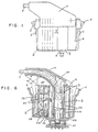
- Fig. 4 is a partial section through the body 1 of the connector, the plane of the section corresponding to the plane of the section in Fig. 2.
- the plug 8 has, extending upwards from the bottom in Fig. 4, a free-standing pin member 31 introducible into a matching aperture in a companion connector, a cylindrical part 32 and a square-section encoding part 34 on whose periphery an encoding projection 35 can be provided at various places to prevent misconnection between light waveguide plugs for different plug chambers during the assembly of the connector.
- a fixing rib 29 on the wall of that zone of the plug chamber 23 which corresponds to the cylindrical plug 32 enables the plug to be movable axially without tilting.
- a circular shoulder 28 in the plug chamber 23 serves as the support for the corners of the square encoding part 34 and encoding projection 35 of the plug 8.
- a resilient element, preferably a resilient ring 36 made of silicone rubber, is disposed above the encoding part.
- the top part of the light waveguide module 3 takes the form of a support element 24 formed with groove-like channels adapted to receive the light waveguide cables 9.
- the channels extend between the vertical chamber 23 and the substantially horizontal cable outlet 25 in a curve with a radius of curvature greater than the minimal permissible radius of curvature of the cable 9.
- the cross-section of the channels perpendicularly to the plane of the drawing is substantially U-shaped, as is that of the pressing element 16.
- Cutting edges 26 are disposed on the channel side walls near the cable outlet 25, keep the light waveguide cable immobile and prevent it from being pulled.
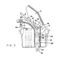
- Fig. 5 is a view, in a partial section corresponding to Fig. 4, of a stage in the assembly of the connector according to the invention.
- the axis recesses 15 in the cap 3 have been pushed on to the pivot projections 21 on the two lateral surfaces of the body 1.
- the cap 7 can be rotated freely around the axis A defined by the pivot until reaching the state shown in Fig. 5.
- the bottom left corner 19 of the pressing element 16 contacts the vertical wall surface 41.
- the U-members of the pressing element are so dimensioned as either not to contact at all or just to wipe the cable 9 in this state.
- the cap Since the pressing element is deformable perpendicularly to the direction of its support arms 18, the cap can in this state be further turned anticlockwise, the corner 19 sliding along the wall surface 41. This enables pivoting to occur and ensures that the U-members 17 do not apply any shear force to the cable 9 during assembly.
- the length of the pressing element is such that once the recesses 14 have engaged the projections 22 the pressing element exerts pressure on the resilient ring 36 and thus presses the plug 8 towards the abutment.
- the support element 24 has plate-like support flanks 27 which transmit to the electrical connector module a pressure applied to the cap 7, thus ensuring that the light waveguide cables can be pressed between the cutting edges 26 to the full depth.
- the electric cables can be led out laterally without hindrance between or adjacent the latter flanks.
- the fully assembled state of the connector is shown in a complete cross-sectional view in Fig. 6.
- the connector is so disposed in a mounting (not shown) that the plug 8 is pressed by way of its end face on a transmitter or receiver element 51.
- Pressure is produced by compression of the resilient ring 36, the plug 8 having disengaged from its abutment surface in the plug chamber.
- the cable 9 disengages simultaneously from the support element 24 and is displaced self-supportingly transversely of its direction in the gap 29 between the element 24 and the surface 11, thus ensuring that the cable 9 is not upset and possibly kinked.
- Fig. 6 shows more details concerning the modular construction of the connector.
- the electrical connector module 2 comprises in known manner a number of plug chambers 52 having a generally known slider 53 for secondary locking of the contacts.
- the light waveguide module 3 is connected to the lateral modules 2, 4 by dovetail guides 56 which are identical on both sides of the module 3.
- dovetail guides 56 which are identical on both sides of the module 3.
- the module 2 has on its back an encoding bevel 59 which merges into the support element 24 and the blank module 4 has a "blunt" corner adapted to the shape of the bevel 59 and formed with a recess near the dovetail guide, thus ensuring that the modules 2, 4 cannot be confused when the body 1 is being assembled.
- the U-members 17 can be entirely omitted so that the support arms press directly on the resilient ring 36.
- the deformability of the pressing element 16 can be ensured not only by the use of resilient material for the support arms but also by the use of film hinges or narrowings in the support arms 18.
- the depth of the recesses 14, 15 in the cap 7 can differ from what is shown in Fig. 2 and can be equal to the thickness of the side flanks 12 - i.e., they can take the form of edge incisions.
Landscapes
- Physics & Mathematics (AREA)
- General Physics & Mathematics (AREA)
- Optics & Photonics (AREA)
- Mechanical Coupling Of Light Guides (AREA)
- Endoscopes (AREA)
Claims (15)
- LWL-Steckverbinder mit abgewinkeltem Kabelabgang, mit einem Körper (1), in dem ein oder mehrere LWL-Stecker (8) in durchgehenden Kammern (23) angeordnet sind, einem mit dem Körper (1) verbundenen Trägerelement (24) mit einem oder mehreren Kanälen zur Aufnahme von LWL-Kabeln (9) abgewinkelt zur Achse der mit ihnen verbundenen LWL-Stecker (8), einer Abdeckkappe (7) zum Schließen der Kanäle, wobei die Abdeckkappe (7) zum Schließen um eine Achse (A) drehbar ist und ein Druckelement (16) aufweist, das in der Nähe der Achse (A) auf die Stecker drückt, um diese in ihrer Kammer (23) festzuhalten, und daß die Abdeckkappe (7) in geschlossenem Zustand die LWL-Kabel (9) in den Kanälen einklemmt.
- Steckverbinder nach Anspruch 1, wobei der Körper (1) und die Abdeckkappe (7) komplementäre Vorsprünge (21, 22) und Aussparungen (15, 14) aufweisen, die die Achse (A) für die Schließbewegung der Abdeckkappe (7) und/oder eine Rastverbindung zwischen dem Körper (1) und der Abdeckkappe (7) definieren.
- Steckverbinder nach Anspruch 2, wobei die Aussparungen (14, 15) zu den Rändern der Abdeckkappe (7) hin offen sind.
- Steckverbinder nach Anspruch 2 oder 3, wobei die die Achse (A) definierenden Aussparungen (15) zum Rand der Abdeckkappe (7) hin trichterförmig erweitert sind.
- Steckverbinder nach einem der Ansprüche 2 bis 4, wobei die Wand (41) der Kammer (23) einen Anschlag bildet, der im Laufe der Schließbewegung das Druckelement (16) verformt, um zu verhindern, daß das Druckelement bei der Schließbewegung seitlich gegen das LWL-Kabel (9) drückt.
- Steckverbinder nach einem der Ansprüche 1 bis 5, wobei das Druckelement (16) über ein elastisches Element (36) den LWL-Stecker (8) gegen einen Anschlag (28) drückt.
- Steckverbinder nach Anspruch 6, wobei das elastische Element (36) ein Ring aus Siliconkautschuk ist.
- Steckverbinder nach einem der Ansprüche 1 bis 7, wobei das LWL-Kabel (9) in einem Zwischenraum (29) zwischen dem Trägerelement (24) und der Abdeckkappe (7) verschiebbar ist.
- Steckverbinder nach einem der Ansprüche 1 bis 8, wobei der LWL-Stecker (8) einen Kodierabschnitt (34) aufweist, der an der Wand der Kammer (23) verdrehsicher geführt ist.
- Steckverbinder nach einem der Ansprüche 1 bis 9, wobei der Körper (1) aus einem LWL-Modul (3), das die Kammern (23) der LWL-Stecker aufnimmt, und ein oder mehreren seitlich an das LWL-Modul (3) angeschlossenen Erweiterungsmodulen (2, 4) aufgebaut ist, wobei wenigstens eines der Erweiterungsmodule (2) Kammern (52) für elektrische Kontaktelemente enthält.
- Steckverbinder nach Anspruch 2 und Anspruch 10, wobei die Zapfen (21) an einem Erweiterungsmodul (4) angebracht sind, das an der von der Kabelabgangsrichtung abgewandten Seite des LWL-Moduls (3) angeschlossen ist, und daß ein in Kabelabgangsrichtung angeschlossenes Erweiterungsmodul (2) Rastvorsprünge (22) aufweist, die in Aussparungen (14) der Abdeckkappe (7) eingreifen.
- Steckverbinder nach Anspruch 10 oder Anspruch 11, wobei das Trägerelement (24) an seiner Unterseite eine Kodierschräge (59) aufweist, die sicherstellt, daß nur ein Erweiterungsmodul (2) mit einer zu der Kodierschräge (59) passenden Aussparung in Kabelabgangsrichtung an das LWL-Modul (3) angeschlossen werden kann.
- Steckverbinder nach einem der Ansprüche 10 bis 12, wobei das Trägerelement (24) wenigstens eine Stützflanke (27) aufweist, die auf den Seiten- oder Zwischenwänden eines in Kabelabgangsrichtung an das LWL-Modul (3) angeschlossenen Erweiterungsmoduls (4) aufliegt.
- Steckverbinder nach einem der Ansprüche 1 bis 13, wobei die rinnenförmigen Kanäle im Trägerelement (24) in der Nähe des Kabelabgangs (25) Schneidkanten (26) aufweisen, die eine Zugentlastung für die LWL-Kabel (9) bilden.
- Steckverbinder nach einem der Ansprüche 10 bis 14, wobei das LWL-Modul (3) und die Erweiterungsmodule (2, 4) durch Schwalbenschwanzführungen (56) verbunden und lösbar verrastet sind, wobei der untere Bereich des LWL-Moduls (3) zum Schließen und/oder Öffnen der Rastverbindung elastisch verformbar ist.
Applications Claiming Priority (2)
| Application Number | Priority Date | Filing Date | Title |
|---|---|---|---|
| DE19525739A DE19525739C1 (de) | 1995-07-14 | 1995-07-14 | Lichtwellenleiterstecker |
| DE19525739 | 1995-07-14 |
Publications (3)
| Publication Number | Publication Date |
|---|---|
| EP0753772A2 EP0753772A2 (de) | 1997-01-15 |
| EP0753772A3 EP0753772A3 (de) | 1997-07-09 |
| EP0753772B1 true EP0753772B1 (de) | 1998-09-30 |
Family
ID=7766859
Family Applications (1)
| Application Number | Title | Priority Date | Filing Date |
|---|---|---|---|
| EP96106370A Expired - Lifetime EP0753772B1 (de) | 1995-07-14 | 1996-04-23 | Lichtwellenleiter-Steckverbindung |
Country Status (3)
| Country | Link |
|---|---|
| EP (1) | EP0753772B1 (de) |
| DE (1) | DE19525739C1 (de) |
| ES (1) | ES2123314T3 (de) |
Families Citing this family (7)
| Publication number | Priority date | Publication date | Assignee | Title |
|---|---|---|---|---|
| US6154597A (en) * | 1998-01-05 | 2000-11-28 | Molex Incorporated | Fiber optic termination system including a fiber optic connector assembly and method of fabricating same |
| FR2779240A1 (fr) * | 1998-06-02 | 1999-12-03 | Framatome Connectors France | Connecteur pour fibres optiques |
| DE19845854C2 (de) | 1998-10-05 | 2000-11-02 | Framatome Connectors Int | Lichtwellenleiter-Steckverbinder für eine mechanischlösbare Verbindung zwischen-mindestens einem LWL-Steckerpaar-mindestens einem LWL-Stecker und einer Leiterplatte |
| DE10101812A1 (de) * | 2001-01-17 | 2002-08-14 | Harting Automotive Gmbh & Co | Optischer Steckverbinder |
| WO2003003060A2 (en) | 2001-06-26 | 2003-01-09 | Viasystems Groups, Inc. | Bending an optical fiber into a backplane |
| EP2546688A1 (de) * | 2011-07-14 | 2013-01-16 | Tyco Electronics Nederland B.V. | Rechtwinkliges optisches Verbindungssystem |
| DE102012217211A1 (de) * | 2012-09-24 | 2014-03-27 | Tyco Electronics Amp Gmbh | Kontaktgehäuse mit Positionierungsmittel zur Lagefixierung eines knickempfindlichen Kabels |
Family Cites Families (4)
| Publication number | Priority date | Publication date | Assignee | Title |
|---|---|---|---|---|
| GB2032130B (en) * | 1978-05-24 | 1982-06-30 | Secr Defence | Fibre optic connectors |
| NL8403691A (nl) * | 1984-12-05 | 1986-07-01 | Philips Nv | Optische verbindingsinrichting. |
| DE4102534A1 (de) * | 1991-01-29 | 1992-08-06 | Reinshagen Kabelwerk Gmbh | Armatur zur loesbaren verbindung zweier lichtwellenleiter |
| DE4412571C1 (de) * | 1994-04-13 | 1995-06-08 | Framatome Connectors Int | Kombinierter LWL-/Metallkabel-Steckverbinder |
-
1995
- 1995-07-14 DE DE19525739A patent/DE19525739C1/de not_active Expired - Fee Related
-
1996
- 1996-04-23 ES ES96106370T patent/ES2123314T3/es not_active Expired - Lifetime
- 1996-04-23 EP EP96106370A patent/EP0753772B1/de not_active Expired - Lifetime
Also Published As
| Publication number | Publication date |
|---|---|
| DE19525739C1 (de) | 1996-10-02 |
| EP0753772A2 (de) | 1997-01-15 |
| ES2123314T3 (es) | 1999-01-01 |
| EP0753772A3 (de) | 1997-07-09 |
Similar Documents
| Publication | Publication Date | Title |
|---|---|---|
| US4449015A (en) | Connector cover with multiple mounting means | |
| US7037129B2 (en) | Axial latch actuator with locking wedge | |
| EP0448476B1 (de) | Elektrischer Verbinder | |
| JPH0329276A (ja) | 電気コネクタ | |
| US20030220008A1 (en) | Axial latch actuator | |
| US4779950A (en) | Connection apparatus for optical fibers | |
| US4611887A (en) | Fiber optic connector assembly and wall outlet thereof | |
| US5037325A (en) | Panel mounted electrical connector | |
| US5313546A (en) | Hermetically sealed joint cover for fibre optic cables | |
| US5685731A (en) | Strain-relief device for use with cable-plug assemblies | |
| US5328382A (en) | Electrical connector with external seal and internal terminal retaining means | |
| EP0955697A1 (de) | Wasserdichter Verbinder | |
| EP0685750A1 (de) | Stecker zum Verbinden eines faseroptischen Kabels | |
| US5529512A (en) | Connector with low insertion force | |
| US5033980A (en) | Electrical connector with a double locking structure for terminals | |
| EP0753772B1 (de) | Lichtwellenleiter-Steckverbindung | |
| US11525963B2 (en) | Optical connection system, optical connector, and optical adapter for use with optical cable assembly and receptacle | |
| KR102415154B1 (ko) | 피드백을 갖는 정합 보조를 구비한 전기 커넥터 | |
| JPH054789B2 (de) | ||
| CA2287741C (en) | Fail-safe optical connector | |
| US5634826A (en) | Electrical connector | |
| EP3700035B1 (de) | Modularer verteilerkasten für kabel | |
| CA1044345A (en) | Strain relief grommet | |
| US6132256A (en) | Design of a lambda module with mating plug | |
| JP2002533745A (ja) | プラグハウジングを有する、光導波路用プラグ |
Legal Events
| Date | Code | Title | Description |
|---|---|---|---|
| PUAI | Public reference made under article 153(3) epc to a published international application that has entered the european phase |
Free format text: ORIGINAL CODE: 0009012 |
|
| AK | Designated contracting states |
Kind code of ref document: A2 Designated state(s): BE ES FR GB IT NL SE |
|
| PUAL | Search report despatched |
Free format text: ORIGINAL CODE: 0009013 |
|
| AK | Designated contracting states |
Kind code of ref document: A3 Designated state(s): BE ES FR GB IT NL SE |
|
| 17P | Request for examination filed |
Effective date: 19970603 |
|
| GRAG | Despatch of communication of intention to grant |
Free format text: ORIGINAL CODE: EPIDOS AGRA |
|
| GRAG | Despatch of communication of intention to grant |
Free format text: ORIGINAL CODE: EPIDOS AGRA |
|
| GRAH | Despatch of communication of intention to grant a patent |
Free format text: ORIGINAL CODE: EPIDOS IGRA |
|
| 17Q | First examination report despatched |
Effective date: 19980223 |
|
| GRAH | Despatch of communication of intention to grant a patent |
Free format text: ORIGINAL CODE: EPIDOS IGRA |
|
| GRAA | (expected) grant |
Free format text: ORIGINAL CODE: 0009210 |
|
| AK | Designated contracting states |
Kind code of ref document: B1 Designated state(s): BE ES FR GB IT NL SE |
|
| RIN1 | Information on inventor provided before grant (corrected) |
Inventor name: HITZ, JUERGEN Inventor name: MUELLER, STEFFAN Inventor name: MAY, GUNTRAM |
|
| REG | Reference to a national code |
Ref country code: ES Ref legal event code: FG2A Ref document number: 2123314 Country of ref document: ES Kind code of ref document: T3 |
|
| ET | Fr: translation filed | ||
| PLBE | No opposition filed within time limit |
Free format text: ORIGINAL CODE: 0009261 |
|
| STAA | Information on the status of an ep patent application or granted ep patent |
Free format text: STATUS: NO OPPOSITION FILED WITHIN TIME LIMIT |
|
| 26N | No opposition filed | ||
| REG | Reference to a national code |
Ref country code: GB Ref legal event code: IF02 |
|
| PGFP | Annual fee paid to national office [announced via postgrant information from national office to epo] |
Ref country code: ES Payment date: 20050317 Year of fee payment: 10 |
|
| PGFP | Annual fee paid to national office [announced via postgrant information from national office to epo] |
Ref country code: SE Payment date: 20050408 Year of fee payment: 10 |
|
| PGFP | Annual fee paid to national office [announced via postgrant information from national office to epo] |
Ref country code: GB Payment date: 20050420 Year of fee payment: 10 Ref country code: BE Payment date: 20050420 Year of fee payment: 10 |
|
| PGFP | Annual fee paid to national office [announced via postgrant information from national office to epo] |
Ref country code: NL Payment date: 20050429 Year of fee payment: 10 |
|
| PG25 | Lapsed in a contracting state [announced via postgrant information from national office to epo] |
Ref country code: GB Free format text: LAPSE BECAUSE OF NON-PAYMENT OF DUE FEES Effective date: 20060423 |
|
| PG25 | Lapsed in a contracting state [announced via postgrant information from national office to epo] |
Ref country code: SE Free format text: LAPSE BECAUSE OF NON-PAYMENT OF DUE FEES Effective date: 20060424 Ref country code: ES Free format text: LAPSE BECAUSE OF NON-PAYMENT OF DUE FEES Effective date: 20060424 |
|
| PG25 | Lapsed in a contracting state [announced via postgrant information from national office to epo] |
Ref country code: BE Free format text: LAPSE BECAUSE OF NON-PAYMENT OF DUE FEES Effective date: 20060430 |
|
| PGFP | Annual fee paid to national office [announced via postgrant information from national office to epo] |
Ref country code: IT Payment date: 20060430 Year of fee payment: 11 |
|
| PG25 | Lapsed in a contracting state [announced via postgrant information from national office to epo] |
Ref country code: NL Free format text: LAPSE BECAUSE OF NON-PAYMENT OF DUE FEES Effective date: 20061101 |
|
| EUG | Se: european patent has lapsed | ||
| GBPC | Gb: european patent ceased through non-payment of renewal fee |
Effective date: 20060423 |
|
| NLV4 | Nl: lapsed or anulled due to non-payment of the annual fee |
Effective date: 20061101 |
|
| REG | Reference to a national code |
Ref country code: ES Ref legal event code: FD2A Effective date: 20060424 |
|
| BERE | Be: lapsed |
Owner name: *FRAMATOME CONNECTORS INTERNATIONAL Effective date: 20060430 |
|
| PGFP | Annual fee paid to national office [announced via postgrant information from national office to epo] |
Ref country code: FR Payment date: 20070404 Year of fee payment: 12 |
|
| REG | Reference to a national code |
Ref country code: FR Ref legal event code: ST Effective date: 20081231 |
|
| PG25 | Lapsed in a contracting state [announced via postgrant information from national office to epo] |
Ref country code: FR Free format text: LAPSE BECAUSE OF NON-PAYMENT OF DUE FEES Effective date: 20080430 |
|
| PG25 | Lapsed in a contracting state [announced via postgrant information from national office to epo] |
Ref country code: IT Free format text: LAPSE BECAUSE OF NON-PAYMENT OF DUE FEES Effective date: 20070423 |