EP0753661A1 - Dispositif d'injection pour un moteur - Google Patents
Dispositif d'injection pour un moteur Download PDFInfo
- Publication number
- EP0753661A1 EP0753661A1 EP96105505A EP96105505A EP0753661A1 EP 0753661 A1 EP0753661 A1 EP 0753661A1 EP 96105505 A EP96105505 A EP 96105505A EP 96105505 A EP96105505 A EP 96105505A EP 0753661 A1 EP0753661 A1 EP 0753661A1
- Authority
- EP
- European Patent Office
- Prior art keywords
- injection
- cam
- engine
- pressure
- injection device
- Prior art date
- Legal status (The legal status is an assumption and is not a legal conclusion. Google has not performed a legal analysis and makes no representation as to the accuracy of the status listed.)
- Withdrawn
Links
Images

Classifications
-
- F—MECHANICAL ENGINEERING; LIGHTING; HEATING; WEAPONS; BLASTING
- F02—COMBUSTION ENGINES; HOT-GAS OR COMBUSTION-PRODUCT ENGINE PLANTS
- F02M—SUPPLYING COMBUSTION ENGINES IN GENERAL WITH COMBUSTIBLE MIXTURES OR CONSTITUENTS THEREOF
- F02M63/00—Other fuel-injection apparatus having pertinent characteristics not provided for in groups F02M39/00 - F02M57/00 or F02M67/00; Details, component parts, or accessories of fuel-injection apparatus, not provided for in, or of interest apart from, the apparatus of groups F02M39/00 - F02M61/00 or F02M67/00; Combination of fuel pump with other devices, e.g. lubricating oil pump
- F02M63/02—Fuel-injection apparatus having several injectors fed by a common pumping element, or having several pumping elements feeding a common injector; Fuel-injection apparatus having provisions for cutting-out pumps, pumping elements, or injectors; Fuel-injection apparatus having provisions for variably interconnecting pumping elements and injectors alternatively
- F02M63/0225—Fuel-injection apparatus having a common rail feeding several injectors ; Means for varying pressure in common rails; Pumps feeding common rails
-
- F—MECHANICAL ENGINEERING; LIGHTING; HEATING; WEAPONS; BLASTING
- F02—COMBUSTION ENGINES; HOT-GAS OR COMBUSTION-PRODUCT ENGINE PLANTS
- F02D—CONTROLLING COMBUSTION ENGINES
- F02D41/00—Electrical control of supply of combustible mixture or its constituents
- F02D41/008—Controlling each cylinder individually
- F02D41/0087—Selective cylinder activation, i.e. partial cylinder operation
-
- F—MECHANICAL ENGINEERING; LIGHTING; HEATING; WEAPONS; BLASTING
- F02—COMBUSTION ENGINES; HOT-GAS OR COMBUSTION-PRODUCT ENGINE PLANTS
- F02D—CONTROLLING COMBUSTION ENGINES
- F02D41/00—Electrical control of supply of combustible mixture or its constituents
- F02D41/22—Safety or indicating devices for abnormal conditions
-
- F—MECHANICAL ENGINEERING; LIGHTING; HEATING; WEAPONS; BLASTING
- F02—COMBUSTION ENGINES; HOT-GAS OR COMBUSTION-PRODUCT ENGINE PLANTS
- F02D—CONTROLLING COMBUSTION ENGINES
- F02D41/00—Electrical control of supply of combustible mixture or its constituents
- F02D41/30—Controlling fuel injection
- F02D41/38—Controlling fuel injection of the high pressure type
- F02D41/3809—Common rail control systems
-
- F—MECHANICAL ENGINEERING; LIGHTING; HEATING; WEAPONS; BLASTING
- F02—COMBUSTION ENGINES; HOT-GAS OR COMBUSTION-PRODUCT ENGINE PLANTS
- F02D—CONTROLLING COMBUSTION ENGINES
- F02D41/00—Electrical control of supply of combustible mixture or its constituents
- F02D41/30—Controlling fuel injection
- F02D41/38—Controlling fuel injection of the high pressure type
- F02D41/40—Controlling fuel injection of the high pressure type with means for controlling injection timing or duration
- F02D41/402—Multiple injections
-
- F—MECHANICAL ENGINEERING; LIGHTING; HEATING; WEAPONS; BLASTING
- F02—COMBUSTION ENGINES; HOT-GAS OR COMBUSTION-PRODUCT ENGINE PLANTS
- F02M—SUPPLYING COMBUSTION ENGINES IN GENERAL WITH COMBUSTIBLE MIXTURES OR CONSTITUENTS THEREOF
- F02M63/00—Other fuel-injection apparatus having pertinent characteristics not provided for in groups F02M39/00 - F02M57/00 or F02M67/00; Details, component parts, or accessories of fuel-injection apparatus, not provided for in, or of interest apart from, the apparatus of groups F02M39/00 - F02M61/00 or F02M67/00; Combination of fuel pump with other devices, e.g. lubricating oil pump
- F02M63/0003—Fuel-injection apparatus having a cyclically-operated valve for connecting a pressure source, e.g. constant pressure pump or accumulator, to an injection valve held closed mechanically, e.g. by springs, and automatically opened by fuel pressure
- F02M63/0007—Fuel-injection apparatus having a cyclically-operated valve for connecting a pressure source, e.g. constant pressure pump or accumulator, to an injection valve held closed mechanically, e.g. by springs, and automatically opened by fuel pressure using electrically actuated valves
-
- F—MECHANICAL ENGINEERING; LIGHTING; HEATING; WEAPONS; BLASTING
- F02—COMBUSTION ENGINES; HOT-GAS OR COMBUSTION-PRODUCT ENGINE PLANTS
- F02B—INTERNAL-COMBUSTION PISTON ENGINES; COMBUSTION ENGINES IN GENERAL
- F02B3/00—Engines characterised by air compression and subsequent fuel addition
- F02B3/06—Engines characterised by air compression and subsequent fuel addition with compression ignition
-
- F—MECHANICAL ENGINEERING; LIGHTING; HEATING; WEAPONS; BLASTING
- F02—COMBUSTION ENGINES; HOT-GAS OR COMBUSTION-PRODUCT ENGINE PLANTS
- F02D—CONTROLLING COMBUSTION ENGINES
- F02D2200/00—Input parameters for engine control
- F02D2200/02—Input parameters for engine control the parameters being related to the engine
- F02D2200/06—Fuel or fuel supply system parameters
- F02D2200/0602—Fuel pressure
-
- F—MECHANICAL ENGINEERING; LIGHTING; HEATING; WEAPONS; BLASTING
- F02—COMBUSTION ENGINES; HOT-GAS OR COMBUSTION-PRODUCT ENGINE PLANTS
- F02D—CONTROLLING COMBUSTION ENGINES
- F02D2250/00—Engine control related to specific problems or objectives
- F02D2250/31—Control of the fuel pressure
-
- Y—GENERAL TAGGING OF NEW TECHNOLOGICAL DEVELOPMENTS; GENERAL TAGGING OF CROSS-SECTIONAL TECHNOLOGIES SPANNING OVER SEVERAL SECTIONS OF THE IPC; TECHNICAL SUBJECTS COVERED BY FORMER USPC CROSS-REFERENCE ART COLLECTIONS [XRACs] AND DIGESTS
- Y02—TECHNOLOGIES OR APPLICATIONS FOR MITIGATION OR ADAPTATION AGAINST CLIMATE CHANGE
- Y02T—CLIMATE CHANGE MITIGATION TECHNOLOGIES RELATED TO TRANSPORTATION
- Y02T10/00—Road transport of goods or passengers
- Y02T10/10—Internal combustion engine [ICE] based vehicles
- Y02T10/40—Engine management systems
Definitions
- the invention relates to an injection device for an engine with feed pumps, in particular heavy oil feed pumps, which can be controlled via cams of a control shaft and which is delivered from a pump pressure chamber via a high-pressure collecting chamber to controlled injection valves of the engine cylinders.
- the invention has for its object to enable a correspondingly large number of delivery processes in a medium-speed engine with a plurality of cylinders by means of delivery pumps which work together with a fine high-pressure plenum chamber with a corresponding crank angle.
- a control shaft of the motor has a plurality of multiple cams, by means of which a number of interconnected feed pumps can be controlled.
- a feed pump is assigned to each multiple cam. It is envisaged that according to the number of engine cylinders and Number of cam lobes on the multiple cam, the number of activated pumps can be determined.
- valve drives of medium-speed four-stroke engines will preferably still be operated by cam drives in the future.
- a control system is also necessary if the feed pumps are no longer driven by the motor-side part of the control shaft.
- Heavy fuel injection pumps are used, be it mechanically with control edges or valve-controlled or electronically controlled. It is crucial that the cams no longer need to have sharp overrun contours to actuate the injection pumps, but can deliver them much more slowly.
- a multiple cam can drive the individual pumps, so that the number of cylinders can be divided by this number of cam lobes according to the number of cam lobes on a cam.
- a nine-cylinder engine could accordingly be charged with three injection pumps and triple cams each in the last three drive holes facing the control drive.
- the setpoint pressure which is dependent on the speed and medium pressure, acts directly on the delivery rate control of the injection pumps in the constant pressure accumulator. This can be done either purely electrically or, in the simplest case, by hydraulic actuation of an actuating cylinder.
- the engine can be started such that after about ten revolutions of the engine with starting air there is at least a pressure of 300 bar, which allows the necessary starting fuel to be injected.
- the aforementioned regulation of the injection quantity of the feed pumps is compared with the torque of the engine, for example as a function of boost pressure or exhaust gas temperature, so that over-injection by a stuck injection valve cannot occur.
- An injection device for an engine has two to four feed pumps, in particular heavy oil feed pumps, which can be controlled by means of multiple cams on a control shaft.
- the multiple cams are arranged on the control shaft and have n-cam elevations corresponding to the number of cylinders.
- a feed pump is operated via each multiple cam.
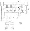
- the feed pumps 23 are connected to the individual injection valves E via lines 35, 36 with the interposition of a high-pressure accumulator H of a constant-pressure injection system K.
- an electronic controller R is connected upstream of the injection valves E, in which signals are received by the feed pumps 23 via the lines 38 and processed accordingly to control the injection valves E.
- signals about the pressure in the high-pressure accumulator H are fed to the controller R via the lines 37.
- pressure in a high-pressure container of the reservoir H is kept at a desired pressure.
- the injection valves E are fed from this pressure vessel. These generally control a time cross-section in accordance with the time and quantity specification.
- the feed pumps 23 fill the high-pressure accumulator H.
- the pumps 23 receive a full quantity specification, which is determined from the desired injection pressure and the injection quantity. Each injection results in a pressure reduction in the high-pressure accumulator H. Every pump delivery results in a brief increase in pressure in this accumulator H.
- the aim is to couple a removal and filling of the high-pressure accumulator H in such a way that the desired injection pressure is present each time the injection process is initiated. Otherwise, the control of the pure time cross section via fluctuating pressures would lead to fluctuating injection quantities.
- FIG. 1 two multiple cams 11, 12, each with three cam elevations 13, 14, are provided for a 6-cylinder engine on a common control shaft 10. These cam lobes are each arranged at an angle of 120 o to one another. A feed pump is arranged on each multiple cam 11, 12, which is not shown in more detail.
- the ignition sequence in this embodiment is, for example, 1,2,4,6,5,3,1, the number identifying the cylinder of the engine. The principle is possible with any other common firing order.
- FIG. 2 two multiple cams 15, 16 each with four cam lobes 17, 18 are provided for an 8-cylinder engine.
- the cam lobes are at an angle of 90 o to each other.
- Each multiple cam 15, 16 has a feed pump.
- the ignition sequence in this embodiment is, for example, 1,2,4,6,8,7,5,3,1. Any other common firing order is conceivable.
- Fig. 3 four multiple cams 19 to 22 an 8-cylinder engine are shown.
- the cam lobes are at an angle of 180 o to each other.
- Each multiple cam 19 to 22 has a pump 23.
- the ignition sequence corresponds, for example, to that of the exemplary embodiment according to FIG. 2.
- FIG. 4 shows a 7-cylinder engine with multiple cams 24 and 26, 27. These multiple cams have two or three cam elevations 25 and 28, respectively.
- the cam lobes are at an angle of 102.9 o to each other.
- the multiple cams 26, 27 are designed with two cam elevations 28, these are at an angle of 205.7 o or 154.3 o to one another.
- the firing order is, for example, 1,2,4,6,7,5,3,1. Any other, even slightly asymmetrical firing order is possible if the double and triple cam take up this angular sequence.
- cam lobes 32 is provided for a 9-cylinder engine, three multiple cam 29,30,31, which are each arranged at an angle of 120 o to each other.
- the firing order is, for example, 1,2,4,6,8,9,7,5,3,1.
- Each multiple cam of the aforementioned designs, as shown in FIGS. 1 to 5, are equipped with a separate heavy oil-capable feed pump, which is not shown.
Landscapes
- Engineering & Computer Science (AREA)
- Chemical & Material Sciences (AREA)
- Combustion & Propulsion (AREA)
- Mechanical Engineering (AREA)
- General Engineering & Computer Science (AREA)
- Fuel-Injection Apparatus (AREA)
Applications Claiming Priority (2)
| Application Number | Priority Date | Filing Date | Title |
|---|---|---|---|
| DE19525694A DE19525694A1 (de) | 1995-07-14 | 1995-07-14 | Einspritzeinrichtung für einen Motor |
| DE19525694 | 1995-07-14 |
Publications (1)
| Publication Number | Publication Date |
|---|---|
| EP0753661A1 true EP0753661A1 (fr) | 1997-01-15 |
Family
ID=7766826
Family Applications (1)
| Application Number | Title | Priority Date | Filing Date |
|---|---|---|---|
| EP96105505A Withdrawn EP0753661A1 (fr) | 1995-07-14 | 1996-04-06 | Dispositif d'injection pour un moteur |
Country Status (2)
| Country | Link |
|---|---|
| EP (1) | EP0753661A1 (fr) |
| DE (1) | DE19525694A1 (fr) |
Families Citing this family (3)
| Publication number | Priority date | Publication date | Assignee | Title |
|---|---|---|---|---|
| DE19857555A1 (de) * | 1998-12-14 | 2000-06-15 | Bayerische Motoren Werke Ag | Direkteinspritzende fremdgezündete Brennkraftmaschine |
| DE102009040683A1 (de) | 2009-09-08 | 2011-03-10 | Daimler Ag | Einspritzpumpe |
| DE102014006450A1 (de) | 2014-05-02 | 2015-11-19 | Daimler Ag | Betätigungseinrichtung zum Betätigen einer Pumpe einer Verbrennungskraftmaschine sowie Verbrennungskraftmaschine mit einer solchen Betätigungseinrichtung |
Citations (6)
| Publication number | Priority date | Publication date | Assignee | Title |
|---|---|---|---|---|
| US4777921A (en) * | 1986-05-02 | 1988-10-18 | Nippondenso Co., Ltd. | Fuel injection system |
| EP0375944A2 (fr) * | 1988-11-24 | 1990-07-04 | Nippondenso Co., Ltd. | Pompe à haute pression à écoulement variable |
| JPH04191460A (ja) * | 1990-11-22 | 1992-07-09 | Nippondenso Co Ltd | ディーゼル機関の高圧燃料ポンプ |
| EP0501459A2 (fr) * | 1991-02-27 | 1992-09-02 | Nippondenso Co., Ltd. | Système d'injection avec rampe à carburant commune et méthode à cet effet |
| EP0501463A2 (fr) * | 1991-02-27 | 1992-09-02 | Nippondenso Co., Ltd. | Système d'injection de carburant avec distributeur pour un moteur |
| EP0507191A1 (fr) * | 1991-04-04 | 1992-10-07 | Toyota Jidosha Kabushiki Kaisha | Dispositif d'injection de combustible pour moteur à combustion interne |
Family Cites Families (2)
| Publication number | Priority date | Publication date | Assignee | Title |
|---|---|---|---|---|
| US5197438A (en) * | 1987-09-16 | 1993-03-30 | Nippondenso Co., Ltd. | Variable discharge high pressure pump |
| DE4301069A1 (de) * | 1993-01-16 | 1994-07-21 | Daimler Benz Ag | Kraftstoffeinspritzanlage für eine mehrzylindrige Diesel-Brennkraftmaschine |
-
1995
- 1995-07-14 DE DE19525694A patent/DE19525694A1/de not_active Withdrawn
-
1996
- 1996-04-06 EP EP96105505A patent/EP0753661A1/fr not_active Withdrawn
Patent Citations (6)
| Publication number | Priority date | Publication date | Assignee | Title |
|---|---|---|---|---|
| US4777921A (en) * | 1986-05-02 | 1988-10-18 | Nippondenso Co., Ltd. | Fuel injection system |
| EP0375944A2 (fr) * | 1988-11-24 | 1990-07-04 | Nippondenso Co., Ltd. | Pompe à haute pression à écoulement variable |
| JPH04191460A (ja) * | 1990-11-22 | 1992-07-09 | Nippondenso Co Ltd | ディーゼル機関の高圧燃料ポンプ |
| EP0501459A2 (fr) * | 1991-02-27 | 1992-09-02 | Nippondenso Co., Ltd. | Système d'injection avec rampe à carburant commune et méthode à cet effet |
| EP0501463A2 (fr) * | 1991-02-27 | 1992-09-02 | Nippondenso Co., Ltd. | Système d'injection de carburant avec distributeur pour un moteur |
| EP0507191A1 (fr) * | 1991-04-04 | 1992-10-07 | Toyota Jidosha Kabushiki Kaisha | Dispositif d'injection de combustible pour moteur à combustion interne |
Non-Patent Citations (1)
| Title |
|---|
| PATENT ABSTRACTS OF JAPAN vol. 016, no. 519 (M - 1330) 26 October 1992 (1992-10-26) * |
Also Published As
| Publication number | Publication date |
|---|---|
| DE19525694A1 (de) | 1997-01-16 |
Similar Documents
| Publication | Publication Date | Title |
|---|---|---|
| DE19708152C2 (de) | Kraftstoffeinspritzsystem | |
| DE19732447C2 (de) | Kraftstoffeinspritzsystem und -verfahren | |
| DE69525986T2 (de) | Verfahren und Vorrichtung zur elektronischen Steuerung eines Speicherkraftstoffsystems | |
| WO1998021470A1 (fr) | Systeme d'injection de carburant | |
| DE2739223A1 (de) | Einspritzanlage fuer verbrennungskraftmotoren | |
| DE602005002575T2 (de) | Nockenwellenverstellungseinrichtung für eine Brennkraftmaschine | |
| DE60314468T2 (de) | Kraftstoffpumpenantrieb | |
| EP0590362B1 (fr) | Agencement de came d'entraînement pour entrainer le piston d'une pompe d'injection pour un moteur à combustion interne | |
| DE102008010053B3 (de) | Verfahren zum Synchronisieren eines Einspritzsystems und Verbrennungsmotor | |
| DE10137869A1 (de) | Einspritzanlage und Verfahren zu deren Betrieb | |
| EP1530681B1 (fr) | Dispositif d'injection de carburant d'une machine a combustion interne | |
| EP0753661A1 (fr) | Dispositif d'injection pour un moteur | |
| DE69917599T2 (de) | Nockenwellenkettentrieb für eine Brennkraftmaschine mit zwei obenliegenden Nockenwellen | |
| WO1998035148A2 (fr) | Procede et dispositif pour surveiller la courroie sans fin de transmission d'un moteur a combustion interne | |
| DE10124738A1 (de) | Verfahren und Anlage zum Anlassen einer nockenfreien Brennkraftmaschine | |
| EP1369573B1 (fr) | Procédé pour faire fonctionner un système d'injection de carburant pour moteurs à combustion interne | |
| DE102014006995A1 (de) | Common Rail-System mit mechanischen Pumpeneinheiten | |
| DE3540811A1 (de) | Kraftstoffeinspritzvorrichtung fuer brennkraftmaschinen, insbesondere pumpe-duese fuer luftverdichtende einspritzbrennkraftmaschinen | |
| DE10141765B4 (de) | Verfahren und Vorrichtung zur Kraftstoffdruckbestimmung | |
| DE2721628A1 (de) | Kraftstoffeinspritzanlage fuer verbrennungskraftmaschinen | |
| WO2016155917A1 (fr) | Dispositif d'injection à haute pression pour moteur à combustion interne | |
| EP1653078A1 (fr) | Machine diesel, en particulier un gros moteur diesel, avec un système de contrôle électronique et une méthode pour démarrer la machine diesel | |
| WO2000011342A1 (fr) | Procede permettant la montee rapide de la pression de carburant dans un accumulateur de carburant | |
| DE2822195C2 (de) | Geteilte, von einem Stellglied betätigte Regelstange für eine Kraftstoffeinspritzpumpe einer Kolbenbrennkraftmaschine | |
| DE102018104856B4 (de) | Verfahren zum Betreiben einer Brennkraftmaschine und Kraftstoffeinspritzsystem |
Legal Events
| Date | Code | Title | Description |
|---|---|---|---|
| PUAI | Public reference made under article 153(3) epc to a published international application that has entered the european phase |
Free format text: ORIGINAL CODE: 0009012 |
|
| AK | Designated contracting states |
Kind code of ref document: A1 Designated state(s): DE FI FR NL |
|
| STAA | Information on the status of an ep patent application or granted ep patent |
Free format text: STATUS: THE APPLICATION IS DEEMED TO BE WITHDRAWN |
|
| 18D | Application deemed to be withdrawn |
Effective date: 19970716 |