EP0753661A1 - Injection device for an engine - Google Patents
Injection device for an engine Download PDFInfo
- Publication number
- EP0753661A1 EP0753661A1 EP96105505A EP96105505A EP0753661A1 EP 0753661 A1 EP0753661 A1 EP 0753661A1 EP 96105505 A EP96105505 A EP 96105505A EP 96105505 A EP96105505 A EP 96105505A EP 0753661 A1 EP0753661 A1 EP 0753661A1
- Authority
- EP
- European Patent Office
- Prior art keywords
- injection
- cam
- engine
- pressure
- injection device
- Prior art date
- Legal status (The legal status is an assumption and is not a legal conclusion. Google has not performed a legal analysis and makes no representation as to the accuracy of the status listed.)
- Withdrawn
Links
Images

Classifications
-
- F—MECHANICAL ENGINEERING; LIGHTING; HEATING; WEAPONS; BLASTING
- F02—COMBUSTION ENGINES; HOT-GAS OR COMBUSTION-PRODUCT ENGINE PLANTS
- F02M—SUPPLYING COMBUSTION ENGINES IN GENERAL WITH COMBUSTIBLE MIXTURES OR CONSTITUENTS THEREOF
- F02M63/00—Other fuel-injection apparatus having pertinent characteristics not provided for in groups F02M39/00 - F02M57/00 or F02M67/00; Details, component parts, or accessories of fuel-injection apparatus, not provided for in, or of interest apart from, the apparatus of groups F02M39/00 - F02M61/00 or F02M67/00; Combination of fuel pump with other devices, e.g. lubricating oil pump
- F02M63/02—Fuel-injection apparatus having several injectors fed by a common pumping element, or having several pumping elements feeding a common injector; Fuel-injection apparatus having provisions for cutting-out pumps, pumping elements, or injectors; Fuel-injection apparatus having provisions for variably interconnecting pumping elements and injectors alternatively
- F02M63/0225—Fuel-injection apparatus having a common rail feeding several injectors ; Means for varying pressure in common rails; Pumps feeding common rails
-
- F—MECHANICAL ENGINEERING; LIGHTING; HEATING; WEAPONS; BLASTING
- F02—COMBUSTION ENGINES; HOT-GAS OR COMBUSTION-PRODUCT ENGINE PLANTS
- F02D—CONTROLLING COMBUSTION ENGINES
- F02D41/00—Electrical control of supply of combustible mixture or its constituents
- F02D41/008—Controlling each cylinder individually
- F02D41/0087—Selective cylinder activation, i.e. partial cylinder operation
-
- F—MECHANICAL ENGINEERING; LIGHTING; HEATING; WEAPONS; BLASTING
- F02—COMBUSTION ENGINES; HOT-GAS OR COMBUSTION-PRODUCT ENGINE PLANTS
- F02D—CONTROLLING COMBUSTION ENGINES
- F02D41/00—Electrical control of supply of combustible mixture or its constituents
- F02D41/22—Safety or indicating devices for abnormal conditions
-
- F—MECHANICAL ENGINEERING; LIGHTING; HEATING; WEAPONS; BLASTING
- F02—COMBUSTION ENGINES; HOT-GAS OR COMBUSTION-PRODUCT ENGINE PLANTS
- F02D—CONTROLLING COMBUSTION ENGINES
- F02D41/00—Electrical control of supply of combustible mixture or its constituents
- F02D41/30—Controlling fuel injection
- F02D41/38—Controlling fuel injection of the high pressure type
- F02D41/3809—Common rail control systems
-
- F—MECHANICAL ENGINEERING; LIGHTING; HEATING; WEAPONS; BLASTING
- F02—COMBUSTION ENGINES; HOT-GAS OR COMBUSTION-PRODUCT ENGINE PLANTS
- F02D—CONTROLLING COMBUSTION ENGINES
- F02D41/00—Electrical control of supply of combustible mixture or its constituents
- F02D41/30—Controlling fuel injection
- F02D41/38—Controlling fuel injection of the high pressure type
- F02D41/40—Controlling fuel injection of the high pressure type with means for controlling injection timing or duration
- F02D41/402—Multiple injections
-
- F—MECHANICAL ENGINEERING; LIGHTING; HEATING; WEAPONS; BLASTING
- F02—COMBUSTION ENGINES; HOT-GAS OR COMBUSTION-PRODUCT ENGINE PLANTS
- F02M—SUPPLYING COMBUSTION ENGINES IN GENERAL WITH COMBUSTIBLE MIXTURES OR CONSTITUENTS THEREOF
- F02M63/00—Other fuel-injection apparatus having pertinent characteristics not provided for in groups F02M39/00 - F02M57/00 or F02M67/00; Details, component parts, or accessories of fuel-injection apparatus, not provided for in, or of interest apart from, the apparatus of groups F02M39/00 - F02M61/00 or F02M67/00; Combination of fuel pump with other devices, e.g. lubricating oil pump
- F02M63/0003—Fuel-injection apparatus having a cyclically-operated valve for connecting a pressure source, e.g. constant pressure pump or accumulator, to an injection valve held closed mechanically, e.g. by springs, and automatically opened by fuel pressure
- F02M63/0007—Fuel-injection apparatus having a cyclically-operated valve for connecting a pressure source, e.g. constant pressure pump or accumulator, to an injection valve held closed mechanically, e.g. by springs, and automatically opened by fuel pressure using electrically actuated valves
-
- F—MECHANICAL ENGINEERING; LIGHTING; HEATING; WEAPONS; BLASTING
- F02—COMBUSTION ENGINES; HOT-GAS OR COMBUSTION-PRODUCT ENGINE PLANTS
- F02B—INTERNAL-COMBUSTION PISTON ENGINES; COMBUSTION ENGINES IN GENERAL
- F02B3/00—Engines characterised by air compression and subsequent fuel addition
- F02B3/06—Engines characterised by air compression and subsequent fuel addition with compression ignition
-
- F—MECHANICAL ENGINEERING; LIGHTING; HEATING; WEAPONS; BLASTING
- F02—COMBUSTION ENGINES; HOT-GAS OR COMBUSTION-PRODUCT ENGINE PLANTS
- F02D—CONTROLLING COMBUSTION ENGINES
- F02D2200/00—Input parameters for engine control
- F02D2200/02—Input parameters for engine control the parameters being related to the engine
- F02D2200/06—Fuel or fuel supply system parameters
- F02D2200/0602—Fuel pressure
-
- F—MECHANICAL ENGINEERING; LIGHTING; HEATING; WEAPONS; BLASTING
- F02—COMBUSTION ENGINES; HOT-GAS OR COMBUSTION-PRODUCT ENGINE PLANTS
- F02D—CONTROLLING COMBUSTION ENGINES
- F02D2250/00—Engine control related to specific problems or objectives
- F02D2250/31—Control of the fuel pressure
-
- Y—GENERAL TAGGING OF NEW TECHNOLOGICAL DEVELOPMENTS; GENERAL TAGGING OF CROSS-SECTIONAL TECHNOLOGIES SPANNING OVER SEVERAL SECTIONS OF THE IPC; TECHNICAL SUBJECTS COVERED BY FORMER USPC CROSS-REFERENCE ART COLLECTIONS [XRACs] AND DIGESTS
- Y02—TECHNOLOGIES OR APPLICATIONS FOR MITIGATION OR ADAPTATION AGAINST CLIMATE CHANGE
- Y02T—CLIMATE CHANGE MITIGATION TECHNOLOGIES RELATED TO TRANSPORTATION
- Y02T10/00—Road transport of goods or passengers
- Y02T10/10—Internal combustion engine [ICE] based vehicles
- Y02T10/40—Engine management systems
Definitions
- the invention relates to an injection device for an engine with feed pumps, in particular heavy oil feed pumps, which can be controlled via cams of a control shaft and which is delivered from a pump pressure chamber via a high-pressure collecting chamber to controlled injection valves of the engine cylinders.
- the invention has for its object to enable a correspondingly large number of delivery processes in a medium-speed engine with a plurality of cylinders by means of delivery pumps which work together with a fine high-pressure plenum chamber with a corresponding crank angle.
- a control shaft of the motor has a plurality of multiple cams, by means of which a number of interconnected feed pumps can be controlled.
- a feed pump is assigned to each multiple cam. It is envisaged that according to the number of engine cylinders and Number of cam lobes on the multiple cam, the number of activated pumps can be determined.
- valve drives of medium-speed four-stroke engines will preferably still be operated by cam drives in the future.
- a control system is also necessary if the feed pumps are no longer driven by the motor-side part of the control shaft.
- Heavy fuel injection pumps are used, be it mechanically with control edges or valve-controlled or electronically controlled. It is crucial that the cams no longer need to have sharp overrun contours to actuate the injection pumps, but can deliver them much more slowly.
- a multiple cam can drive the individual pumps, so that the number of cylinders can be divided by this number of cam lobes according to the number of cam lobes on a cam.
- a nine-cylinder engine could accordingly be charged with three injection pumps and triple cams each in the last three drive holes facing the control drive.
- the setpoint pressure which is dependent on the speed and medium pressure, acts directly on the delivery rate control of the injection pumps in the constant pressure accumulator. This can be done either purely electrically or, in the simplest case, by hydraulic actuation of an actuating cylinder.
- the engine can be started such that after about ten revolutions of the engine with starting air there is at least a pressure of 300 bar, which allows the necessary starting fuel to be injected.
- the aforementioned regulation of the injection quantity of the feed pumps is compared with the torque of the engine, for example as a function of boost pressure or exhaust gas temperature, so that over-injection by a stuck injection valve cannot occur.
- An injection device for an engine has two to four feed pumps, in particular heavy oil feed pumps, which can be controlled by means of multiple cams on a control shaft.
- the multiple cams are arranged on the control shaft and have n-cam elevations corresponding to the number of cylinders.
- a feed pump is operated via each multiple cam.
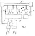
- the feed pumps 23 are connected to the individual injection valves E via lines 35, 36 with the interposition of a high-pressure accumulator H of a constant-pressure injection system K.
- an electronic controller R is connected upstream of the injection valves E, in which signals are received by the feed pumps 23 via the lines 38 and processed accordingly to control the injection valves E.
- signals about the pressure in the high-pressure accumulator H are fed to the controller R via the lines 37.
- pressure in a high-pressure container of the reservoir H is kept at a desired pressure.
- the injection valves E are fed from this pressure vessel. These generally control a time cross-section in accordance with the time and quantity specification.
- the feed pumps 23 fill the high-pressure accumulator H.
- the pumps 23 receive a full quantity specification, which is determined from the desired injection pressure and the injection quantity. Each injection results in a pressure reduction in the high-pressure accumulator H. Every pump delivery results in a brief increase in pressure in this accumulator H.
- the aim is to couple a removal and filling of the high-pressure accumulator H in such a way that the desired injection pressure is present each time the injection process is initiated. Otherwise, the control of the pure time cross section via fluctuating pressures would lead to fluctuating injection quantities.
- FIG. 1 two multiple cams 11, 12, each with three cam elevations 13, 14, are provided for a 6-cylinder engine on a common control shaft 10. These cam lobes are each arranged at an angle of 120 o to one another. A feed pump is arranged on each multiple cam 11, 12, which is not shown in more detail.
- the ignition sequence in this embodiment is, for example, 1,2,4,6,5,3,1, the number identifying the cylinder of the engine. The principle is possible with any other common firing order.
- FIG. 2 two multiple cams 15, 16 each with four cam lobes 17, 18 are provided for an 8-cylinder engine.
- the cam lobes are at an angle of 90 o to each other.
- Each multiple cam 15, 16 has a feed pump.
- the ignition sequence in this embodiment is, for example, 1,2,4,6,8,7,5,3,1. Any other common firing order is conceivable.
- Fig. 3 four multiple cams 19 to 22 an 8-cylinder engine are shown.
- the cam lobes are at an angle of 180 o to each other.
- Each multiple cam 19 to 22 has a pump 23.
- the ignition sequence corresponds, for example, to that of the exemplary embodiment according to FIG. 2.
- FIG. 4 shows a 7-cylinder engine with multiple cams 24 and 26, 27. These multiple cams have two or three cam elevations 25 and 28, respectively.
- the cam lobes are at an angle of 102.9 o to each other.
- the multiple cams 26, 27 are designed with two cam elevations 28, these are at an angle of 205.7 o or 154.3 o to one another.
- the firing order is, for example, 1,2,4,6,7,5,3,1. Any other, even slightly asymmetrical firing order is possible if the double and triple cam take up this angular sequence.
- cam lobes 32 is provided for a 9-cylinder engine, three multiple cam 29,30,31, which are each arranged at an angle of 120 o to each other.
- the firing order is, for example, 1,2,4,6,8,9,7,5,3,1.
- Each multiple cam of the aforementioned designs, as shown in FIGS. 1 to 5, are equipped with a separate heavy oil-capable feed pump, which is not shown.
Abstract
Description
Die Erfindung bezieht sich auf eine Einspritzeinrichtung für einen Motor mit Förderpumpen, insbesondere Schweröl-Förderpumpen, die über Nocken einer Steuerwelle ansteuerbar sind und eine Förderung von einem Pumpendruckraum über einen Hochdrucksammelraum zu gesteuerten Einspritzventilen der Motorzylinder erfolgt.The invention relates to an injection device for an engine with feed pumps, in particular heavy oil feed pumps, which can be controlled via cams of a control shaft and which is delivered from a pump pressure chamber via a high-pressure collecting chamber to controlled injection valves of the engine cylinders.
Es ist bei Viertaktmittelmotoren vorhersehbar, daß ein Betrieb mit Schweröl möglich ist und Konstantdruck-Einspritzsysteme verwendet werden. Um eine Bereitstellung der Einspritzmenge bei richtigem Druck sicherzustellen sind darüber hinaus Schwerölförderpumpen erforderlich.It is foreseeable with four-stroke mid-engine that operation with heavy oil is possible and constant pressure injection systems are used. Heavy oil feed pumps are also required to ensure that the injection quantity is available at the correct pressure.
Der Erfindung liegt die Aufgabe zugrunde, bei einem Mittelschnelläufermotor mit mehreren Zylindern entsprechend viele Fördervorgänge durch Förderpumpen , die mit feinem Hochdrucksammelraum zusammenarbeiten, bei einem entsprechenden Kurbelwinkel zu ermöglichen.The invention has for its object to enable a correspondingly large number of delivery processes in a medium-speed engine with a plurality of cylinders by means of delivery pumps which work together with a fine high-pressure plenum chamber with a corresponding crank angle.
Diese Aufgabe wird erfindungsgemäß durch die kennzeichnenden Merkmale des Anspruchs 1 gelöst. Weitere vorteilhafte Merkmale beinhalten die Unteransprüche.This object is achieved according to the invention by the characterizing features of claim 1. The dependent claims contain further advantageous features.
Eine Steuerwelle des Motors weist mehrere Mehrfachnocken auf, über die mehrere zusammengeschaltete Förderpumpen ansteuerbar sind. Jedem Mehrfachnocken ist eine Förderpumpe zugeordnet. Es ist vorgesehen, daß entsprechend der Anzahl der Motorzylinder sowie der Anzahl der Nockenerhebungen auf dem Mehrfachnocken, die Anzahl der angesteuerten Pumpen bestimmbar sind.A control shaft of the motor has a plurality of multiple cams, by means of which a number of interconnected feed pumps can be controlled. A feed pump is assigned to each multiple cam. It is envisaged that according to the number of engine cylinders and Number of cam lobes on the multiple cam, the number of activated pumps can be determined.
Es ist erforderlich, daß wenn die Förderung von Einspritzmenge und Einspritzdruck so erfolgt, daß nach jedem Fördervorgang in einen Zylinder hinein eine Förderung von der Förderpumpe in das Konstantdruck-Einspritzsystem erfolgt. Außerdem soll der jeweilige Fördervorgang den gleichen zeitlichen Abstand von der Einspritzung haben. Ist dies nicht der Fall, so wird die schnelle elektronische Regelung gerade bei langsam laufenden Motoren zu Regelstörungen führen.It is necessary that if the delivery of the injection quantity and the injection pressure takes place in such a way that after each delivery operation, delivery into a cylinder takes place from the delivery pump into the constant pressure injection system. In addition, the respective delivery process should have the same time interval from the injection. If this is not the case, the fast electronic control will lead to control malfunctions, especially with slow running motors.
Beim Zusammenschalten der Schwerölförderpumpen für einen Konstantdruck-Einspritzsystem muß mit etwas höheren mittleren Antriebsmomenten gerechnet werden, als bei einer bisherigen Einspritzung, weil mit einem höheren Druck in einen Speicher gefördert wird, als dort selbst zur Wirkung kommt. Dies ergibt sich aus den Differenzflächen üblicher Ventile. Der Antrieb für eine solche Fördereinheit, sollte also in jedem Fall so kräftig sein, wie ein entsprechender für konventionelle Einspritzung. Außerdem verbietet es sich bei normalen Motoren, eine solche Förderpumpe am freien Motorende anzutreiben. Die logische Ausführung für den Anbau von Förderpumpen in das Konstantdruck-Einspritzsystem ist bei mittelschneilaufenden Viertaktmotoren also der Nahbereich des Nockenwellen-Zahnrades, sei es nun vom Motor wegbauend oder hin zu den Ventilantrieben.When interconnecting the heavy oil feed pumps for a constant pressure injection system, somewhat higher average drive torques must be expected than with a previous injection, because a higher pressure is pumped into a storage device than is effective there. This results from the differential areas of conventional valves. The drive for such a delivery unit should in any case be as powerful as a corresponding one for conventional injection. In addition, it is forbidden for normal motors to drive such a feed pump at the free end of the motor. The logical design for the installation of feed pumps in the constant pressure injection system in medium-speed four-stroke engines is the close range of the camshaft gear, be it from the engine or towards the valve drives.
Die Ventilantriebe von mittelschnell laufenden Viertaktmotoren werden auch zukünftig vorzugsweise noch durch Nockenantriebe betätigt werden. Eine Steuerwelie ist also auch dann nötig, wenn die Förderpumpen nicht mehr vom motorseitigen Teil der Steuerweile angetrieben würden.The valve drives of medium-speed four-stroke engines will preferably still be operated by cam drives in the future. A control system is also necessary if the feed pumps are no longer driven by the motor-side part of the control shaft.
Es werden Schweröl-Einspritzförderpumpen verwendet, sei es nun mechanisch mit Steuerkanten oder ventilgesteuerte oder elektronisch kontrollierte. Entscheidend ist, daß die Nocken zum Betätigen der Einspritzpumpen keine scharfe Auflaufkonturen mehr zu haben brauchen, sondern deutlich langsamer fördern können. Andererseits kann ein Mehrfachnocken die einzelnen Pumpen antreiben, so daß - entsprechend der Anzahl der Nockenerhebungen auf einem Nocken, die Zylinderanzahl durch diese Anzahl der Nockenerhebung geteilt werden kann. Ein Neunzylindermotor könnte demgemäß mit drei Einspritzpumpen und jeweils Dreifachnocken in den drei letzten, dem Steuerungsantrieb zugewandten Antriebslöchern beaufschlagt werden. Um aber eine möglichst geringe Stoßbeanspruchung des Steuerantriebes zu haben - will man doch die Leistung auch noch weiterhin steigern - so wird vorzugsweise vorgeschlagen, daß für jede Pumpe nur ein Doppelnocken verwendet wird. Dies ist bei geraden Zylinderzahlen möglich; es ergeben sich dann leicht versetzte Doppelnocken. Bei ungeraden ylinderzahlen gibt es zusätzlich einen Antrieb mit nur einem Nockenauflauf. Die Erhebungskurven aller Nockenbahnen stehen natürlich im Verhältnis von 360o geteilt durch die Anzahl der Zylinder zueinander, und nach wie vor sind die doppelt angetriebenen Pumpen sehr nahe am Steuerungsantrieb.Heavy fuel injection pumps are used, be it mechanically with control edges or valve-controlled or electronically controlled. It is crucial that the cams no longer need to have sharp overrun contours to actuate the injection pumps, but can deliver them much more slowly. On the other hand, a multiple cam can drive the individual pumps, so that the number of cylinders can be divided by this number of cam lobes according to the number of cam lobes on a cam. A nine-cylinder engine could accordingly be charged with three injection pumps and triple cams each in the last three drive holes facing the control drive. However, in order to have as little impact stress on the control drive as possible - one still wants to further increase the output - it is preferably suggested that only one double cam be used for each pump. This is possible with an even number of cylinders; there are then slightly offset double cams. If the number of cylinders is odd, there is also a drive with only one cam overrun. The elevation curves of all cam tracks are of course in a ratio of 360 o divided by the number of cylinders to each other, and the double-driven pumps are still very close to the control drive.
In weiterer Ausgestaltung wird vorgeschlagen, daß der von Geschwindigkeit und Mitteldruck abhängige Solldruck im Konstantdruckspeicher direkt auf die Fördermengenregelung der Einspritzpumpen einwirkt. Dies kann sowohl rein elektrisch geschehen als auch im einfachsten Falle über die hydraulische Beaufschlagung eines Stellzylinders.In a further embodiment, it is proposed that the setpoint pressure, which is dependent on the speed and medium pressure, acts directly on the delivery rate control of the injection pumps in the constant pressure accumulator. This can be done either purely electrically or, in the simplest case, by hydraulic actuation of an actuating cylinder.
Desweiteren ist vorgesehen, daß auch bei abgesunkenem Druck im Konstantdruckspeicher der Motor so gestartet werden kann, daß etwa nach zehn Umdrehungen des Motors mit Startluft mindestens ein Druck von 300 bar anliegt, der es gestattet, den nötigen Startkraftstoff einzuspritzen.Furthermore, it is provided that, even when the pressure in the constant pressure accumulator has dropped, the engine can be started such that after about ten revolutions of the engine with starting air there is at least a pressure of 300 bar, which allows the necessary starting fuel to be injected.
Die vorgenannte Regulierung der Einspritzmenge der Förderpumpen wird mit dem Drehmoment des Motors verglichen, zum Beispiel als Funktion von Ladedruck oder Abgastemperatur, so daß eine Übereinspritzung durch ein hängengebliebenes Einspritzventil nicht vorkommen kann.The aforementioned regulation of the injection quantity of the feed pumps is compared with the torque of the engine, for example as a function of boost pressure or exhaust gas temperature, so that over-injection by a stuck injection valve cannot occur.
In einer Zeichnung sind mehrere Ausführungsbeispiele der Erfindung dargestellt, die im folgenden näher beschrieben werden. Es zeigen:
- Fig. 1
- eine schematische Darstellung von zwei Dreifachnocken eines 6-Zylinder-Motors,
- Fig. 2
- eine schematische Darstellung von zwei Vierfachnocken eines 8-Zylinder-Motors,
- Fig. 3
- eine schematische Darstellung von zwei Zweifachnocken eine 8-Zylinder-Motors,
- Fig. 4
- eine schematische Darstellung von zwei Zwei- bzw. von einem Dreifachnocken eines 7-Zylinder-Motors ,
- Fig. 5
- eine schematische Darstellung von drei Dreifachnocken eines 9-Zylinder-Motors und
- Fig. 6
- eine schematische Darstellung eines Konstantdruck-Einspritzsystems mit Hochdruckspeicher.
- Fig. 1
- 1 shows a schematic representation of two triple cams of a 6-cylinder engine,
- Fig. 2
- 1 shows a schematic representation of two quadruple cams of an 8-cylinder engine,
- Fig. 3
- a schematic representation of two double cams an 8-cylinder engine,
- Fig. 4
- 1 shows a schematic representation of two double or one triple cam of a 7-cylinder engine,
- Fig. 5
- a schematic representation of three triple cams of a 9-cylinder engine and
- Fig. 6
- is a schematic representation of a constant pressure injection system with high pressure accumulator.
Eine Einspritzeinrichtung für einen Motor, weist zwei bis vier Förderpumpen, insbesondere Schweröl-Förderpumpen auf, die über Mehrfachnocken auf einer Steuerwelle ansteuerbar sind. Die Mehrfachnocken sind auf der Steuerwelle angeordnet, und weisen n-Nockenerhebungen entsprechend der Anzahl der Zylinder auf. Über jeden Mehrfachnocken wird eine Förderpumpe betrieben.An injection device for an engine has two to four feed pumps, in particular heavy oil feed pumps, which can be controlled by means of multiple cams on a control shaft. The multiple cams are arranged on the control shaft and have n-cam elevations corresponding to the number of cylinders. A feed pump is operated via each multiple cam.
Die Förderpumpen 23 sind über Leitungen 35,36 unter Zwischenschaltung eines Hochdruckspeichers H eines Konstantdruck-Einspritzsystems K mit den einzelnen Einspritzventilen E verbunden. Zur Mengensteuerung ist den Einspritzventilen E ein elektronischer Regler R vorgeschaltet, in dem Signale über die Leitungen 38 von den Förderpumpen 23 aufgenommen und entsprechend zur Ansteuerung der Einspritzventile E verarbeitet werden. Ebenfalls werden dem Regler R über die Leitungen 37 Signale über den Druck im Hochdruckspeicher H zugeführt.The
Bei der Steuerung wird Druck in einem Hochdruckbehälter des Speichers H auf einen gewünschten Druck gehalten. Aus diesem Druckbehälter werden die Einspritzventile E gespeist. Diese steuern im allgemeinen einen Zeitquerschnitt auf entsprechend der Zeit und Mengenvorgabe. Die Förderpumpen 23 befüllen den Hochdruckspeicher H. Die Pumpen 23 erhalten eine Mengenvollvorgabe, die sich aus dem gewünschten Einspritzdruck und der Einspritzmenge bestimmt. Jede Einspritzung ergibt einen Druckabbau im Hochdruckspeicher H. Jede Pumpenförderung ergibt kurzzeitig eine Druckerhöhung in diesem Speicher H.In the control, pressure in a high-pressure container of the reservoir H is kept at a desired pressure. The injection valves E are fed from this pressure vessel. These generally control a time cross-section in accordance with the time and quantity specification. The feed pumps 23 fill the high-pressure accumulator H. The pumps 23 receive a full quantity specification, which is determined from the desired injection pressure and the injection quantity. Each injection results in a pressure reduction in the high-pressure accumulator H. Every pump delivery results in a brief increase in pressure in this accumulator H.
Bei zeitlich ungeregelter Folge von Entnahme und Zuförderung ergibt sich während jeder Einspritzsteuerung ein nicht genau bekannter Druck im Hochdrucksystem K und damit ohne komplizierte Regelungen ungenaue Einspritzungen.If the sequence of removal and delivery is unregulated in time, the pressure in the high-pressure system K is not exactly known during each injection control and thus inaccurate injections without complicated regulations.
Das Ziel ist es, eine Entnahme und Befüllung des Hochdruckspeichers H zeitlich so zu koppeln, daß bei jeder Einleitung des Einspritzvorganges der gewünschte Einspritzdruck anliegt. Sonst würde die Steuerung des reinen Zeitquerschnitts über schwankende Drücke zu schwankenden Einspritzmengen führen.The aim is to couple a removal and filling of the high-pressure accumulator H in such a way that the desired injection pressure is present each time the injection process is initiated. Otherwise, the control of the pure time cross section via fluctuating pressures would lead to fluctuating injection quantities.
In Fig. 1 sind für einen 6-Zylindermotor auf einer gemeinsamen Steuerwelle 10 zwei Mehrfachnocken 11,12 mit jeweils drei Nockenerhebungen 13,14 vorgesehen. Diese Nockenerhebungen sind jeweils im Winkel von 120o zueinander angeordnet. Auf jedem Mehrfachnocken 11,12 ist jeweils eine Förderpumpe angeordnet, die nicht näher eingezeichnet ist. Die Zündfolge bei dieser Ausführung ist beispielsweise 1,2,4,6,5,3,1, wobei die Zahl jeweils den Zylinder des Motors kennzeichnet. Das Prinzip ist bei jeder anderen gängigen Zündfolge möglich.In FIG. 1, two
In Fig. 2 sind zwei Mehrfachnocken 15,16 mit jeweils vier Nockenerhebungen 17,18 für einen 8-Zylindermotor vorgesehen. Die Nockenerhebungen stehen unter einem Winkel von 90o zueinander. Jeder Mehrfachnocken 15,16 weist eine Förderpumpe auf. Die Zündfolge bei dieser Ausführung ist beispielsweise 1,2,4,6,8,7,5,3,1. Es ist jede andere gängige Zündfolge denkbar.In Fig. 2, two
In Fig. 3 sind vier Mehrfachnocken 19 bis 22 einen 8-Zylindermotor dargestellt. Die Nockenerhebungen stehen unter einem Winkel von 180o zueinander. Jeder Mehrfachnocken 19 bis 22 weist eine Pumpe 23 auf. Die Zündfolge entspricht beispielsweise der des Ausführungsbeispiels nach Fig. 2.In Fig. 3 four
In Fig. 4 ist ein 7-Zylindermotor mit Mehrfachnocken 24 und 26,27 dargestellt. diese Mehrfachnocken weisen zwei bzw. drei Nockenerhebungen 25 bzw. 28 auf. Die Nockenerhebungen stehen unter einem Winkel von 102,9o zueinander.4 shows a 7-cylinder engine with
Bei der Ausführung der Mehrfachnocken 26,27 mit zwei Nockenerhebungen 28 stehen diese unter einem Winkel von 205,7o bzw. 154,3o zueinander. Die Zündfolge ist beispielsweise 1,2,4,6,7,5,3,1. Jede andere, auch leicht unsymmetrische Zündfolge ist möglich, wenn die Zweifach- und Dreifachnocken diese Winkelfolge aufnimmt.When the
Bei der Ausführung gemäß Fig. 5 sind für einen 9-Zylindermotor drei Mehrfachnocken 29,30,31 mit Nockenerhebungen 32 vorgesehen, die jeweils unter einem Winkel von 120o zueinander angeordnet sind. Die Zündfolge ist beispielsweise 1,2,4,6,8,9,7,5,3,1.In the embodiment of FIG. 5, with
Jeder Mehrfachnocken der vorgenannten Ausführungen, gemäß Fig. 1 bis 5, sind mit einer separaten schwerölfähigen Förderpumpe bestückt, was nicht näher eingezeichnet ist.Each multiple cam of the aforementioned designs, as shown in FIGS. 1 to 5, are equipped with a separate heavy oil-capable feed pump, which is not shown.
Claims (9)
Applications Claiming Priority (2)
| Application Number | Priority Date | Filing Date | Title |
|---|---|---|---|
| DE19525694 | 1995-07-14 | ||
| DE19525694A DE19525694A1 (en) | 1995-07-14 | 1995-07-14 | Injection device for an engine |
Publications (1)
| Publication Number | Publication Date |
|---|---|
| EP0753661A1 true EP0753661A1 (en) | 1997-01-15 |
Family
ID=7766826
Family Applications (1)
| Application Number | Title | Priority Date | Filing Date |
|---|---|---|---|
| EP96105505A Withdrawn EP0753661A1 (en) | 1995-07-14 | 1996-04-06 | Injection device for an engine |
Country Status (2)
| Country | Link |
|---|---|
| EP (1) | EP0753661A1 (en) |
| DE (1) | DE19525694A1 (en) |
Families Citing this family (3)
| Publication number | Priority date | Publication date | Assignee | Title |
|---|---|---|---|---|
| DE19857555A1 (en) * | 1998-12-14 | 2000-06-15 | Bayerische Motoren Werke Ag | Internal combustion engine with direct fuel injection and externally supplied ignition has single cylinder high pressure fuel pump installed on side of cylinder head and operated by longitudinally movable cam follower |
| DE102009040683A1 (en) | 2009-09-08 | 2011-03-10 | Daimler Ag | Injection pump for injection system of internal combustion engine of motor vehicle, has conveying elements and camshaft, where stroke rotation angles of camshaft sequential in rotation direction of camshaft are varied in pairs |
| DE102014006450A1 (en) | 2014-05-02 | 2015-11-19 | Daimler Ag | Actuating device for actuating a pump of an internal combustion engine and internal combustion engine with such an actuator |
Citations (6)
| Publication number | Priority date | Publication date | Assignee | Title |
|---|---|---|---|---|
| US4777921A (en) * | 1986-05-02 | 1988-10-18 | Nippondenso Co., Ltd. | Fuel injection system |
| EP0375944A2 (en) * | 1988-11-24 | 1990-07-04 | Nippondenso Co., Ltd. | Variable-discharge high pressure pump |
| JPH04191460A (en) * | 1990-11-22 | 1992-07-09 | Nippondenso Co Ltd | High pressure fuel pump for diesel engine |
| EP0501463A2 (en) * | 1991-02-27 | 1992-09-02 | Nippondenso Co., Ltd. | Common-rail fuel injection system for an engine |
| EP0501459A2 (en) * | 1991-02-27 | 1992-09-02 | Nippondenso Co., Ltd. | Common-rail fuel injection system and related method |
| EP0507191A1 (en) * | 1991-04-04 | 1992-10-07 | Toyota Jidosha Kabushiki Kaisha | A fuel injection device of an engine |
Family Cites Families (2)
| Publication number | Priority date | Publication date | Assignee | Title |
|---|---|---|---|---|
| US5197438A (en) * | 1987-09-16 | 1993-03-30 | Nippondenso Co., Ltd. | Variable discharge high pressure pump |
| DE4301069A1 (en) * | 1993-01-16 | 1994-07-21 | Daimler Benz Ag | Fuel injection on a diesel engine |
-
1995
- 1995-07-14 DE DE19525694A patent/DE19525694A1/en not_active Withdrawn
-
1996
- 1996-04-06 EP EP96105505A patent/EP0753661A1/en not_active Withdrawn
Patent Citations (6)
| Publication number | Priority date | Publication date | Assignee | Title |
|---|---|---|---|---|
| US4777921A (en) * | 1986-05-02 | 1988-10-18 | Nippondenso Co., Ltd. | Fuel injection system |
| EP0375944A2 (en) * | 1988-11-24 | 1990-07-04 | Nippondenso Co., Ltd. | Variable-discharge high pressure pump |
| JPH04191460A (en) * | 1990-11-22 | 1992-07-09 | Nippondenso Co Ltd | High pressure fuel pump for diesel engine |
| EP0501463A2 (en) * | 1991-02-27 | 1992-09-02 | Nippondenso Co., Ltd. | Common-rail fuel injection system for an engine |
| EP0501459A2 (en) * | 1991-02-27 | 1992-09-02 | Nippondenso Co., Ltd. | Common-rail fuel injection system and related method |
| EP0507191A1 (en) * | 1991-04-04 | 1992-10-07 | Toyota Jidosha Kabushiki Kaisha | A fuel injection device of an engine |
Non-Patent Citations (1)
| Title |
|---|
| PATENT ABSTRACTS OF JAPAN vol. 016, no. 519 (M - 1330) 26 October 1992 (1992-10-26) * |
Also Published As
| Publication number | Publication date |
|---|---|
| DE19525694A1 (en) | 1997-01-16 |
Similar Documents
| Publication | Publication Date | Title |
|---|---|---|
| DE19708152C2 (en) | Fuel injection system | |
| DE19732447C2 (en) | Fuel injection system and method | |
| DE3112381C2 (en) | ||
| WO1998021470A1 (en) | Fuel injector | |
| DE2739223A1 (en) | INJECTION SYSTEM FOR COMBUSTION ENGINES | |
| DE602005002575T2 (en) | Camshaft adjusting device for an internal combustion engine | |
| DE60314468T2 (en) | Fuel pump driving | |
| EP0590362B1 (en) | Cam drive arrangement for driving the pump piston of an injector pump of a four-stroke internal combustion engine | |
| DE102008010053B3 (en) | Method for synchronizing injection system of internal combustion engine, involves detecting crankshaft angle of crankshaft of internal combustion engine by stroke sequence of internal combustion engine | |
| DE10137869A1 (en) | Injection system and method for its operation | |
| EP1530681B1 (en) | Fuel injection device for an internal combustion engine | |
| EP0753661A1 (en) | Injection device for an engine | |
| DE69917599T2 (en) | Camshaft chain drive for an internal combustion engine with two overhead camshafts | |
| EP0963513A2 (en) | Process and device for monitoring an endless driving belt of an internal combustion engine | |
| DE10124738A1 (en) | Starting camless internal combustion engine involves driving each valve according to desired valve drive characteristic, and controlling cylinders according to defined characteristic | |
| EP1369573B1 (en) | Method for operating a fuel injection system for internal combustion engines | |
| DE102014006995A1 (en) | Common rail system with mechanical pump units | |
| DE19619469C1 (en) | Fuel pump drive esp. for common rail fuel injection system for IC engine | |
| DE10141765B4 (en) | Method and device for determining fuel pressure | |
| DE2721628A1 (en) | FUEL INJECTION SYSTEM FOR COMBUSTION ENGINES | |
| WO2016155917A1 (en) | High-pressure injection device for an internal combustion engine | |
| EP1653078A1 (en) | Diesel machine, in particular a big diesel engine, with an electronic control system and a method for starting the diesel machine | |
| EP1109999A1 (en) | Method for the rapid build-up of fuel pressure in a fuel accumulator | |
| DE102018104856B4 (en) | Method for operating an internal combustion engine and fuel injection system | |
| EP0999350B1 (en) | Mechanism for generating control signals for driving an internal combustion engine, and internal combustion engine using the same |
Legal Events
| Date | Code | Title | Description |
|---|---|---|---|
| PUAI | Public reference made under article 153(3) epc to a published international application that has entered the european phase |
Free format text: ORIGINAL CODE: 0009012 |
|
| AK | Designated contracting states |
Kind code of ref document: A1 Designated state(s): DE FI FR NL |
|
| STAA | Information on the status of an ep patent application or granted ep patent |
Free format text: STATUS: THE APPLICATION IS DEEMED TO BE WITHDRAWN |
|
| 18D | Application deemed to be withdrawn |
Effective date: 19970716 |