EP0752899B1 - Abnehmbares absturzsicherungsgerät - Google Patents
Abnehmbares absturzsicherungsgerät Download PDFInfo
- Publication number
- EP0752899B1 EP0752899B1 EP95913266A EP95913266A EP0752899B1 EP 0752899 B1 EP0752899 B1 EP 0752899B1 EP 95913266 A EP95913266 A EP 95913266A EP 95913266 A EP95913266 A EP 95913266A EP 0752899 B1 EP0752899 B1 EP 0752899B1
- Authority
- EP
- European Patent Office
- Prior art keywords
- safety line
- fall arrest
- vertical fall
- arrest device
- rotary member
- Prior art date
- Legal status (The legal status is an assumption and is not a legal conclusion. Google has not performed a legal analysis and makes no representation as to the accuracy of the status listed.)
- Expired - Lifetime
Links
- 230000007246 mechanism Effects 0.000 claims description 24
- 230000005484 gravity Effects 0.000 claims description 6
- 230000004044 response Effects 0.000 claims description 3
- 230000008859 change Effects 0.000 claims description 2
- 230000009471 action Effects 0.000 description 6
- 238000013461 design Methods 0.000 description 5
- 230000000694 effects Effects 0.000 description 3
- 230000015572 biosynthetic process Effects 0.000 description 2
- 238000005755 formation reaction Methods 0.000 description 2
- 238000012423 maintenance Methods 0.000 description 2
- 238000000034 method Methods 0.000 description 2
- 230000004048 modification Effects 0.000 description 2
- 238000012986 modification Methods 0.000 description 2
- 230000000717 retained effect Effects 0.000 description 2
- 125000006850 spacer group Chemical group 0.000 description 2
- 239000000725 suspension Substances 0.000 description 2
- 241000490025 Schefflera digitata Species 0.000 description 1
- 230000009194 climbing Effects 0.000 description 1
- 238000000576 coating method Methods 0.000 description 1
- 230000001010 compromised effect Effects 0.000 description 1
- 230000000881 depressing effect Effects 0.000 description 1
- 230000000994 depressogenic effect Effects 0.000 description 1
- 238000005516 engineering process Methods 0.000 description 1
- 238000003780 insertion Methods 0.000 description 1
- 230000037431 insertion Effects 0.000 description 1
- 238000009434 installation Methods 0.000 description 1
- 230000003993 interaction Effects 0.000 description 1
- 235000015250 liver sausages Nutrition 0.000 description 1
- 230000014759 maintenance of location Effects 0.000 description 1
- 239000000203 mixture Substances 0.000 description 1
- 230000007935 neutral effect Effects 0.000 description 1
- 238000000926 separation method Methods 0.000 description 1
- 230000003245 working effect Effects 0.000 description 1
Images


Classifications
-
- A—HUMAN NECESSITIES
- A62—LIFE-SAVING; FIRE-FIGHTING
- A62B—DEVICES, APPARATUS OR METHODS FOR LIFE-SAVING
- A62B35/00—Safety belts or body harnesses; Similar equipment for limiting displacement of the human body, especially in case of sudden changes of motion
- A62B35/0081—Equipment which can travel along the length of a lifeline, e.g. travelers
- A62B35/0087—Arrangements for bypassing lifeline supports without lanyard disconnection
-
- A—HUMAN NECESSITIES
- A62—LIFE-SAVING; FIRE-FIGHTING
- A62B—DEVICES, APPARATUS OR METHODS FOR LIFE-SAVING
- A62B35/00—Safety belts or body harnesses; Similar equipment for limiting displacement of the human body, especially in case of sudden changes of motion
- A62B35/0043—Lifelines, lanyards, and anchors therefore
- A62B35/005—Vertical lifelines
-
- E—FIXED CONSTRUCTIONS
- E06—DOORS, WINDOWS, SHUTTERS, OR ROLLER BLINDS IN GENERAL; LADDERS
- E06C—LADDERS
- E06C7/00—Component parts, supporting parts, or accessories
- E06C7/18—Devices for preventing persons from falling
-
- E—FIXED CONSTRUCTIONS
- E06—DOORS, WINDOWS, SHUTTERS, OR ROLLER BLINDS IN GENERAL; LADDERS
- E06C—LADDERS
- E06C7/00—Component parts, supporting parts, or accessories
- E06C7/18—Devices for preventing persons from falling
- E06C7/186—Rail or rope for guiding a safety attachment, e.g. a fall arrest system
Definitions
- the present invention relates to vertical fall arrest devices, and in particular to vertical fall arrest devices adapted for easy attachment to and detachment from a safety cable or the like.
- Vertical fall arrest devices are an important accessory for maintenance personnel who climb tall structures since they enable the hazard of falls to be minimised.
- Vertical fall arrest systems which employ a safety line such as a flexible cable for engagement by the fall arrest device require intermediate support brackets to restrain the cable from buffeting against the tall structure while under wind loading. Such systems therefore present a practical problem of enabling the fall arrest device (and the user) to bypass the support brackets without increasing the fall hazard.
- a vertical fall arrest device is known from the present Applicants' earlier European Patent Application No. 0 272 782, which discloses a device comprising the features set out in the preamble of present claim 1.
- the known device suffers from the drawback that it is not readily attachable to nor detachable from an elongate safety line, so special entry/exit gates have to be provided at predetermined locations in a safety line installation. It may sometimes be necessary to detach from and re-attach to the safety line at an intermediate position during a climb or descent of a tall structure. Such an operation is not possible with the prior art device.
- the invention is a vertical fall arrest device for use on an elongate safety line, said device comprising:
- a device constructed in accordance with the invention is especially advantageous because it provides, for the first time in a single unit, the means to arrest a fall, the capability to automatically traverse intermediate support means provided along a safety line, and ease of attachment to or detachment from the safety line at any point throughout its length.
- the relative movement between at least one of the rotary member, the body and the retaining means is movement in a direction away from the other parts.
- the parts may be slidable relative to one another, or they may be rotatable.
- the important feature is the ability to create a gap between them which allows a safety line to be introduced or removed from the space defined between the body member and the rotary member.
- the device incorporates releasable means for maintaining the rotary member, the body and the retaining means in a closed condition in which introduction or removal of a safety line is prevented.
- This feature means that a conscious decision must be taken on the part of the user to open the device.
- the releasable means includes a positive latching mechanism which retains the parts in the closed condition against accidental release.
- the latching mechanism may be biased to its non-release position for added safety.
- the device is converted to the attachment/detachment condition by operating a release mechanism against biasing pressure and at the same time pulling the rotary member against biasing pressure in a direction away from the body. This action creates an opening for insertion or removal of a safety line.
- release means including push button, safety pin, pull-release or rotary mechanisms.
- a spindle upon which the rotary member is rotatably mounted is locked into the body.
- the spindle may not be pulled away from the body without first operating a release catch, and hence disengaging the locking mechanism, by an intentional action.
- the device In the closed and locked condition, it is not possible for the device to be removed from or attached to a safety line. When attached to a safety line, the device is always in a ready state to grip the safety line firmly in the event of a fall.
- the removable vertical fall arrest device of the present invention has a single rotary member in juxtaposition with the body member, it will be apparent to persons skilled in the art that the device is "handed". In a working personnel safety system attached to a tall structure, it is also necessary for the intermediate brackets supporting the safety line to be consistently “handed” for correct traversing.
- the invention may incorporate a safety mechanism which prevents the release means from being actuated. Only when the device is correctly oriented can the release means be moved to an unlatched position allowing the opening of the device and its attachment to a safety line.
- the release means for the latching mechanism incorporates a safety mechanism which alerts the user to the fact that the device is being attached in the wrong orientation.
- the safety mechanism may be in the form of a detent member which is freely-movable under the influence of gravity between first and second positions, according to the orientation of the device.
- the direction of free movement is arranged to be substantially parallel to the suspension axis of the device.
- the detent member engages with the release means and jams it against actuation, thereby discouraging attachment of the device in the wrong orientation. Then, if the device is inverted, the detent member moves to the other position which frees the release means and renders it operable. Only by crossing or changing hands can the user attach the device incorrectly.
- the detent member may be a ball which rolls or a pin which slides in a channel provided in the body member or a cover member associated therewith.
- the detent member may be housed in the release means and may move into a notch or cut-out portion in the body member or its associated cover member.
- the feature which does not house the detent member may be provided with a detent-engaging formation such as a notch or a raised portion to ensure that there is effective interaction with the detent in the non-release condition.
- Another alternative form of detent member is a pawl mounted on a pivot.
- variants of the invention include the provision of a groove on the surface of the rotary member facing the body of the device, for cooperation with a raised projection formed on the body. This helps to maintain the relatively rotatable parts in their respective operating relationships.
- a groove may be provided in the body and/or retaining means which receives a cooperating projection formed on the rotary member.
- the groove may be so formed that it surrounds the head portion of the projection or projections and thereby effects a positive engagement between the cooperating parts.
- Such an arrangement would allow the rotary member, for example, to be positively engaged with the retaining means so that the two are movable as a unitary element in relation to the body member.
- An example of this type of arrangement is one in which the head portion of the projection or projections has a dove-tail cross-section and in which the groove has a corresponding undercut profile.
- neither the body, the retaining means nor the rotary member have any grooves and/or projections.
- the rotary member may be in the form of a wheel having a plurality of petals projecting radially from the hub of the wheel.
- the petals then define, between adjacent pairs thereof, recesses of the type required for automatic traversing of safety line support brackets.
- the provision of a number of recesses may be helpful in aligning the device with respective elements of successive safety line supports during a lengthy climb or descent.
- the device is provided with at least one slipper pad which helps to maintain the desired orientation of the invention with respect to the safety line during climb or descent.
- a slipper pad runs against the safety line in advance of (or behind) the body.
- the slipper pad or pads may be substituted by or equipped with a roller or rollers to assist in normal passage of the device along the safety line.
- one or more rollers may be included in the retaining means to ease passage of the device along the safety line in normal use.
- the position of the roller is chosen such that the lock-on capability of the device is not compromised.
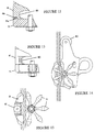
- view (a) shows a typical industrial ladder 10 with a safety line 30 supported centrally an equal distance from its respective stiles 11.
- Safety line 30 is held in position in relation to the ladder 10 by a number of supporting brackets 20 which are in turn supported by the rungs 12 of the ladder 10. Only one such bracket 20 is shown.
- View (b) is a side elevation showing how the suspension axis of the safety line is separated from the plane of the ladder 10 by a pre-determined distance.
- view (a) is a close-up view showing how the safety line 30 passes through a guide tube 24 attached to the bracket body 22 by bracket legs 23.
- View (b) is a view along the axis of the safety line 30 showing how a bracket leg 23 is attached to the guide tube 24.
- the safety line support has an inherent "handedness", the importance of which will become apparent in the explanation below.
- Figure 3 shows a pair of part-sectional views through the invention looking in a direction along the axis of a safety line 30.
- support brackets 20 for the safety line 30 may be installed in either "left-handed” or “right-handed” versions. To accommodate this, the invention is also suitably handed. It is to be noted that, for satisfactory operation of the invention, all support brackets must be handed in the same sense to match the handing of the attachment device. A mixture of left and right handing cannot be accommodated by the invention. Thus, for a safety line system which exclusively employs left-handed brackets, the device shown in Figure 3(a) would be employed. Conversely, for a safety line system with only right-handed brackets, the device of Figure 3(b) would be used.
- FIG 4 there is shown an exploded view of a left-handed version of the invention, such as depicted in Figure 3(a).
- the device includes a cam member 43 which is pivotable on bosses located in a pair of side plates 48 disposed one on either side of the cam member.
- Biasing means in the form of a tension spring 51 is attached to the cam member 43 at one end and to a fixed member such as a dowel 54 at the other end.
- the effect of the biasing means is to bias the pivotal movement of the cam member 43 in a direction towards the lock-on condition in which a safety line 30 is tightly gripped by the device.
- a slipper pad 49 is also secured between the side plates 48.
- the separation between the side plates 48 is determined by a plurality of spacers 52.
- the cam member 43, dowel 54, slipper pad 49 and spacers 52 are all entrapped between the slide pates 48.
- a bolt 45 passes through corresponding holes formed in the side plates 48 and protrudes beyond said side plates 48 at either end.
- the bolt 45 serves as a spindle for a wheel 42 assembled on the outside of the one of the side plates 48.
- the wheel 42 is retained on the spindle by a locknut 50 which engages with a threaded portion at one end of the bolt 45.
- An intermediate disc 46 is also placed on the bolt between the wheel 42 and locknut 50 to ensure freedom of rotation of the wheel 42.
- the bolt 45 passes through a body member 41 which is integrally formed with retaining means in the form of a safety line retaining recess 60. Further biasing means in the form of springs 47 are provided on this side of the device.
- the first of these serves to urge a lock release catch 44 into its non-release position in normal use of the device. The user therefore has to undertake an intentional action to operate the lock release catch 44.
- the second spring 47 serves to urge the wheel 42 into a so-called "closed” position in which at least one of its petals overlies the safety line retaining recess 60.
- a cover member 53 is provided on the head of the bolt 45 and serves to protect some of the operating parts of the device from ingress of dirt.
- Figure 5 shows a side view of the assembled invention with one of the side plates 48 omitted for clarity.
- the configuration of the wheel 42 can be clearly seen. It comprises a central hub 70 which receives the spindle or bolt 45 and a plurality of evenly-spaced radially-projecting petals 71.
- the disposition of the wheel 42 in relation to the body member 41 is such that the petals 71 execute a circular path which overlies the safety line retaining recess 60.
- Figure 5 also shows the cam member 43 in the raised position in which there is no engagement with the safety line 30.
- the cam member 43 In normal use, under neutral loading, the cam member 43 is urged into the lock-on position by a combination of gravity acting on the cam centre of gravity and tension in the tension spring 51. In this condition, the attachment device is firmly locked-on to the safety line 30 for all fall-arrest situations.
- Figure 6 shows the various stages of passage of the invention past a typical safety line support bracket.
- the sequence of steps shown in the views (a) to (d) in fact illustrates a descent sequence, though it will be appreciated by persons skilled in the art that an ascent sequence could be described in analogous fashion.
- Figure 6(a) shows stage 1 in which, due to the handing of the system, the body member 41 runs down and partially entraps the guide tube 24 of a safety line support bracket 20.
- the body member 41 passes behind the curved bracket legs 23 and does not foul on them.
- These legs 23 maybe any shape in cross-section and not necessarily square as shown in the Figure.
- Wheel 42 which lies in a similar plane to the curved bracket legs 23, offers a gap between two adjacent petals 71. Should the situation arise where a gap is not in register with the bracket legs 23, contact between a petal tip and the legs 23 causes the wheel 42 to rotate slightly and thereby bring a gap into alignment with the leg.
- Rotation of the wheel 42 during descent is caused by the weight of the device (and any attachment) being transmitted through contact with one or more bracket legs 23 in such a way that a turning force acts on the wheel 42.
- the turning force on the wheel 42 is opposed by frictional forces occurring between the wheel 42 and the spindle or bolt 45 and also by frictional forces arising from relative movement between the wheel 42 and the body member 41. Such frictional forces may be reduced by the application of low friction coatings or other bearing technology.
- view (a) shows an attachment device according to the invention in the closed and locked condition.
- the central bolt 45 (which also serves as the spindle and retention means for the wheel 42) is locked into the body member 41 and may not be pulled away from it without first operating the lock release catch 44 by an intentional action.
- the device In the closed and locked condition, it is not possible for the device to be removed from or attached to a safety line system.
- the device In the attached condition, i.e. in which a safety line 30 is accommodated in the safety line retaining recess 60, the device is always in a ready state to lock-on to the safety line in the event of a fall.
- the device may then be removed from the safety line system by depressing the release catch 44 against spring pressure and at the same time pulling the wheel in a direction away from the body member 41. Movement of the wheel is also effected against biasing spring pressure. This action creates an opening for withdrawal of the device from the safety line 30.
- the open condition is shown in Figure 7(b).
- Figure 8 shows the internal workings of another, similar embodiment of release catch, in a direction along the axis of a safety line 30.
- cover member 53 has been omitted for clarity.
- the combined wheel and bolt assembly 42, 45 must be grasped and pulled away from the body member 41 in the direction of arrow D, as shown in view (b).
- the biasing pressure of spring 47a urges the assembly to return to the non-release position shown in Figure 8(a).
- Additional return spring 47b urges the lock release catch 44 to its latching position.
- a device constructed in accordance with the invention provides a quick and simple method of attachment to and detachment from a safety line system.
- Figure 9 illustrates a few more ways in which the release mechanism of the invention may be implemented.
- a pull-release lever is shown.
- Figure 9(b) shows a safety pin arrangement, whilst Figure 9(c), which is a side view, shows a rotary release knob.
- Non-illustrated variants are also possible without departing from the scope of the invention as defined in the claims which follow this description.
- Figure 10 shows a variant of the invention incorporating a safety mechanism which minimises the risk of installing the device on a safety line in an inverted orientation.
- views (a), (b), (d) and (e) are end views of a body member 41 and release catch 44 assembly looking in the direction of arrow A in Figure 4.
- Views (c) and (f) are sectional views of the body member and release catch assembly taken on lines cc' and ff' of views (b) and (e), respectively.
- a detent member in the form of a ball 144 is accommodated in a channel 145 machined in the body member 41.
- Ball 144 is freely movable in the channel 145 and its rest position depends on the orientation of the fall arrest device.
- Release catch 44 is formed with a notch 245 in the side thereof adjacent channel 145. The position of notch 245 is arranged to coincide with that of channel 145 when the release catch is in its rest condition, i.e. the non-release condition. If the fall arrest device is oriented such that it might be installed on a safety line the wrong way round, ball 144 falls into notch 245 and prevents movement of the release catch in the release direction. This condition is shown in views (b) and (c).
- FIG 11 shows an alternative safety mechanism which works on similar principles to the safety mechanism described in relation to Figure 10 above.
- views (a), and (b) are part-sectional views of a cover 53 and release catch 44 assembly looking in the direction of arrow B in Figure 4.
- View (c) is an end view of the cover 53 taken on lines cc' of view (b).
- a detent member in the form of a pin 244 is housed in a channel 246 formed in release catch 44.
- Pin 244 is freely movable in the channel 246, its rest position depending on the orientation of the fall arrest device.
- Cover member 53 is formed with a cut-out 153 in one of its internal webs 253. The position of cut-out 153 is arranged to coincide with that of channel 246 when the release catch is in its rest condition, i.e. the non-release condition.
- pin 244 By inverting the fall arrest device to the orientation shown in view (b), pin 244 is caused to travel to the other end of channel 246 under the influence of gravity. At this point, the pin 244 is prevented from further movement which would cause it to foul motion of the release catch 44 in the release direction by continuous web 254.
- This web has no cut-out portion and provides a smooth surface along which the lowermost end of pin 244 can slide in response to motion of release catch 44.
- Web 253 having cut-out portion 153 and continuous web 254 are best seen in Figure 11(c).
- Figures 12, 13, 14 and 15 show a number of design modifications which may be adopted.
- a body member 41 is shown in which a groove 41a is provided for cooperation with a projection 71a formed on each of the petals 71 of the wheel 42 (only one petal shown).
- Figure 13 neither the body member 41 nor the wheel 42 is formed with any projections and/or grooves.
- Figure 14 shows a particular form of slipper which comprises a roller 80 adapted to assist in normal passage of the device along the safety line by engagement therewith in advance of (or behind) the device.
- Figure 15 depicts another modification in which the safety line retaining recess 60 is equipped with a roller 61 to ease passage of the device along the safety line in normal use. The roller 61 is positioned in such a way that it cannot interfere with the lock-on capability of the device in the event of a fall.
Landscapes
- Engineering & Computer Science (AREA)
- Mechanical Engineering (AREA)
- Health & Medical Sciences (AREA)
- General Health & Medical Sciences (AREA)
- Business, Economics & Management (AREA)
- Emergency Management (AREA)
- Emergency Lowering Means (AREA)
- Electrical Discharge Machining, Electrochemical Machining, And Combined Machining (AREA)
- Ladders (AREA)
Claims (14)
- Schutzvorrichtung gegen senkrechte Stürze zur Verwendung an einer länglichen Sicherungsleine (30), wobei die Vorrichtung umfaßt:ein Körperelement (41),ein Drehelement (42), das wenigstens eine Aussparung in seinem Umfang aufweist;eine Haltevorrichtung (49) für die Sicherungsleine, die sich zwischen dem Körperelement (41) und dem Drehelement (42) erstreckt und die so ausgebildet ist, daß sie eine Sicherungsleine (30) in einem zwischen dem Körperelement (41) und dem Drehelement (42) definierten Raum (60) festhält;eine Verriegelungsvorrichtung (43) zum Verriegeln der Vorrichtung an der länglichen Sicherungsleine (30) in einer Sturzschutzsituation;eine Vorspannvorrichtung (51), um die Verriegelungsvorrichtung (43) bei einem plötzlichen Wechsel der von der Vorrichtung aufgenommenen Belastung in einen verriegelnden Eingriff mit der Sicherungsleine (30) zu zwingen, die in der Haltevorrichtung (49) für die Sicherungsleine aufgenommen ist; und eineVorrichtung zum Befestigen eines Personensicherungskabels an der Vorrichtung;
wobei das Drehelement (42) relativ in Bezug auf die Haltevorrichtung (49) drehbar befestigt ist und wobei die oder jede Aussparung so ausgebildet ist, daß sie eine Tragvorrichtung (20), die dazu verwendet wird, eine längliche Sicherungsleine (30) zu tragen, ohne die Notwendigkeit der Beeinflussung durch den Benutzer mittels einer Rotation des Drehelements (42) relativ zu der Haltevorrichtung (49) so durchläuft, daß die Elemente der Tragvorrichtung (20) nachfolgend von einer Aussparung aufgenommen, geführt und automatisch vorbeigeführt werden;
dadurch gekennzeichnet, daß wenigstens ein Element aus der Gruppe des Drehelements (42), des Körperelements (41) oder der Haltevorrichtung (49) relativ zu den anderen Elementen der Gruppe beweglich ist, so daß es ermöglicht wird, eine Sicherungsleine (30) in den Raum (60) einzuführen oder aus dem Raum (60) zu entfernen, so daß die Vorrichtung an der Sicherungsleine (30) befestigt oder von dieser gelöst werden kann. - Schutzvorrichtung gegen senkrechte Stürze nach Anspruch 1, die ferner eine Auslösevorrichtung (44) umfaßt, die das Drehelement (42), das Körperelement (41) und die Haltevorrichtung (49) in einem geschlossenen Zustand hält, in dem der Einsatz oder die Entnahme einer Sicherungsleine (30) verhindert wird.
- Schutzvorrichtung gegen senkrechte Stürze nach Anspruch 2, wobei die Auslösevorrichtung (44) eine formschlüssige Verriegelungsvorrichtung (44a, 45a, 47b) umfaßt.
- Schutzvorrichtung gegen senkrechte Stürze nach Anspruch 3, wobei die formschlüssige Verriegelungsvorrichtung einen Verriegelungsmechnismus (44) umfaßt, der in seiner nicht freigebenden Stellung vorgespannt ist.
- Schutzvorrichtung gegen senkrechte Stürze nach Anspruch 4, wobei eine Auslösevorrichtung für den Verriegelungsmechanismus (44) einen Sicherheitsmechanismus (144, 245) umfaßt, der einen Benutzer vorwarnt, daß die Schutzvorrichtung gegen senkrechte Stürze in der falschen Ausrichtung befestigt ist.
- Schutzvorrichtung gegen senkrechte Stürze nach Anspruch 5, wobei der Sicherheitsmechanismus ein Arretierelement (144, 244) umfaßt, das unter dem Einfluß der Gravitation zwischen einer Eingriffsposition, bei der es die Auslösevorrichtung blockiert und sie gegen eine Aktivierung verriegelt, und einer freien Position, die die Auslösevorrichtung freigibt und sie bedienbar macht, abhängig von der Ausrichtung der Vorrichtung frei beweglich ist.
- Schutzvorrichtung gegen senkrechte Stürze nach Anspruch 6, wobei das Arretierelement eine Kugel (114) oder ein Stift (244) ist, der in einem Kanal (145) in dem Körperelement (41) oder einem zugehörigen Abdeckelement (53) aufgenommen ist.
- Schutzvorrichtung gegen senkrechte Stürze nach Anspruch 6, wobei das Arretierelement eine Kugel (144) oder einen Stift (244) ist, der in einem Kanal (246) in der Auslösevorrichtung (44) aufgenommen ist.
- Schutzvorrichtung gegen senkrechte Stürze nach einem der Ansprüche 2 bis 8, wobei das Drehelement (42) durch eine Vorspannvorrichtung (47a) in die geschlossene Stellung gezwungen wird.
- Schutzvorrichtung gegen senkrechte Stürze nach einem der Ansprüche 2 bis 9, wobei eine zentrale Spindel (45), an der das Drehelement (42) drehbar befestigt ist, lösbar durch die formschlüssige Verriegelungs-Vorrichtung (44a, 45a, 47b) an dem Körperelement (41) verriegelt ist.
- Schutzvorrichtung gegen senkrechte Stürze nach einem der vorhergehenden Ansprüche, wobei das Drehelement (42) mit einer Nut an dessen Oberfläche versehen ist, die in Richtung auf das Körperelement (41) der Vorrichtung für ein Zusammenwirken mit einem erhobenen Vorsprung ausgerichtet ist, der aufdem Körperelement (41) und/oder der Haltevorrichtung (49) ausgebildet ist.
- Schutzvorrichtung gegen senkrechte Stürze nach einem der vorhergehenden Ansprüche, wobei das Drehelement ein Rad (42) ist, das eine Vielzahl von Streben (71) aufweist, die sich radial von der Nabe (70) des Rads (42) aus erstrecken, wobei die Streben (71) zwischen jeweils zwei aneinander angrenzenden Paaren Aussparungen für ein Überbrücken der Tragvorrichtung (20) der Sicherungsleine definieren.
- Schutzvorrichtung gegen senkrechte Stürze nach einem der vorhergehenden Ansprüche, die ferner wenigstens ein Gleitelement (49) zur Beibehaltung der gewünschten Ausrichtung der Vorrichtung während des Aufstiegs oder des Abstiegs in Bezug auf die Sicherungsleine (30) enthält.
- Schutzvorrichtung gegen senkrechte Stürze nach Anspruch 13, wobei der oder die Gleitelemente (49) eine Rolle oder mehrere Rollen sind.
Applications Claiming Priority (3)
| Application Number | Priority Date | Filing Date | Title |
|---|---|---|---|
| GB9406486 | 1994-03-31 | ||
| GB9406486A GB9406486D0 (en) | 1994-03-31 | 1994-03-31 | Removable verticle fall arrester |
| PCT/GB1995/000734 WO1995026784A1 (en) | 1994-03-31 | 1995-03-31 | Removable vertical fall arrest device |
Publications (2)
| Publication Number | Publication Date |
|---|---|
| EP0752899A1 EP0752899A1 (de) | 1997-01-15 |
| EP0752899B1 true EP0752899B1 (de) | 2000-05-31 |
Family
ID=10752879
Family Applications (1)
| Application Number | Title | Priority Date | Filing Date |
|---|---|---|---|
| EP95913266A Expired - Lifetime EP0752899B1 (de) | 1994-03-31 | 1995-03-31 | Abnehmbares absturzsicherungsgerät |
Country Status (8)
| Country | Link |
|---|---|
| US (1) | US6263999B1 (de) |
| EP (1) | EP0752899B1 (de) |
| JP (1) | JPH09511165A (de) |
| AU (1) | AU687181B2 (de) |
| CA (1) | CA2186766C (de) |
| DE (1) | DE69517310T2 (de) |
| GB (1) | GB9406486D0 (de) |
| WO (1) | WO1995026784A1 (de) |
Families Citing this family (22)
| Publication number | Priority date | Publication date | Assignee | Title |
|---|---|---|---|---|
| DE29802037U1 (de) * | 1998-02-06 | 1998-04-02 | Söll GmbH, 95028 Hof | Läufer, der auf einer Schiene gleitet, insbesondere für eine Absturzsicherung |
| GB9823320D0 (en) | 1998-10-23 | 1998-12-23 | Latchways Plc | Two-way locking device for height safety apparatus |
| GB2351057A (en) * | 1999-06-14 | 2000-12-20 | Latchways Plc | Removable load transfer device for height safety apparatus |
| FR2813800B1 (fr) * | 2000-09-13 | 2002-10-11 | Dalloz Fall Prot | Coulisseau pour ligne de vie |
| FR2819727B1 (fr) * | 2001-01-19 | 2005-05-20 | Odco | Dispositif de securite anti-chute |
| US6481695B1 (en) * | 2001-07-13 | 2002-11-19 | The Crosby Group, Inc. | Snatch block hook bolt assembly |
| GB2403256B (en) * | 2003-06-27 | 2006-02-15 | Latchways Plc | Safety line anchor |
| US7168687B2 (en) * | 2004-10-29 | 2007-01-30 | Techxotic Lc | Snatch block, snatch block assembly and method of use |
| US7669835B2 (en) * | 2005-02-02 | 2010-03-02 | Techxotic Lc | Closure system, method of use, and devices including closure system |
| FR2884727B1 (fr) * | 2005-04-22 | 2007-08-17 | Capital Safety Group Emea Sa | Coulisseau pour ligne de vie |
| JP3831791B1 (ja) * | 2005-10-07 | 2006-10-11 | 幹男 小野山 | 安全帯掛止装置 |
| US7533870B2 (en) * | 2006-06-16 | 2009-05-19 | Allan-Vanguard Technologies Inc. | Pulley |
| GB2468273A (en) * | 2009-01-12 | 2010-09-08 | Latchways Plc | A fall arrest system comprising a traveller device and a plastically deformable energy absorber |
| GB0915277D0 (en) * | 2009-09-02 | 2009-10-07 | Latchways Plc | Safety line traveller |
| GB2491808A (en) * | 2011-05-31 | 2012-12-19 | Central High Rise Ltd | Safety clamp which receives safety rail |
| US9138603B2 (en) * | 2012-02-23 | 2015-09-22 | Honeywell International Inc. | Rope adjuster with fast rope replacement device |
| ES2385530B1 (es) * | 2012-03-13 | 2013-05-31 | Escaleras Aguerri, S.L. | Línea de vida vertical para trabajos en altura |
| US10792520B2 (en) | 2014-09-12 | 2020-10-06 | D B Industries, Llc | Personal descent system |
| DE102018007306B3 (de) * | 2018-09-17 | 2020-01-30 | Günzburger Steigtechnik Munk GmbH | Sicherungsläufer |
| US10995842B1 (en) | 2019-01-30 | 2021-05-04 | Summit Rescue, Inc. | Pulley with hinged side plate |
| CN113428252B (zh) * | 2021-08-17 | 2022-07-12 | 深圳市人工智能与机器人研究院 | 一种缆索攀爬机器人 |
| SE547151C2 (en) * | 2023-04-13 | 2025-05-06 | Cwl Patent Ab | An arrangement for guiding a safety line and an installation comprising one or more structures of a building and comprising one or more arrangements |
Family Cites Families (5)
| Publication number | Priority date | Publication date | Assignee | Title |
|---|---|---|---|---|
| US4521000A (en) | 1983-06-06 | 1985-06-04 | Dodge Jr Cleveland E | Bypassing double action rope grip |
| GB8627320D0 (en) | 1986-11-14 | 1986-12-17 | Latchways Ltd | Lockable load-transfer |
| US4923037A (en) * | 1989-06-29 | 1990-05-08 | John Stephenson | Fall arrest device |
| US5156240A (en) * | 1991-05-31 | 1992-10-20 | Meyer Ostrobrod | Rope grab |
| US5316103A (en) * | 1993-01-22 | 1994-05-31 | Michael Bell | Rope grab device indicating the existence of shock impact on personal safety |
-
1994
- 1994-03-31 GB GB9406486A patent/GB9406486D0/en active Pending
-
1995
- 1995-03-31 CA CA002186766A patent/CA2186766C/en not_active Expired - Lifetime
- 1995-03-31 JP JP7525505A patent/JPH09511165A/ja active Pending
- 1995-03-31 DE DE69517310T patent/DE69517310T2/de not_active Expired - Lifetime
- 1995-03-31 WO PCT/GB1995/000734 patent/WO1995026784A1/en not_active Ceased
- 1995-03-31 AU AU20802/95A patent/AU687181B2/en not_active Expired
- 1995-03-31 EP EP95913266A patent/EP0752899B1/de not_active Expired - Lifetime
- 1995-03-31 US US08/732,235 patent/US6263999B1/en not_active Expired - Lifetime
Also Published As
| Publication number | Publication date |
|---|---|
| CA2186766C (en) | 2005-06-21 |
| WO1995026784A1 (en) | 1995-10-12 |
| EP0752899A1 (de) | 1997-01-15 |
| US6263999B1 (en) | 2001-07-24 |
| DE69517310T2 (de) | 2000-11-23 |
| DE69517310D1 (de) | 2000-07-06 |
| GB9406486D0 (en) | 1994-05-25 |
| AU687181B2 (en) | 1998-02-19 |
| JPH09511165A (ja) | 1997-11-11 |
| AU2080295A (en) | 1995-10-23 |
| CA2186766A1 (en) | 1995-10-12 |
Similar Documents
| Publication | Publication Date | Title |
|---|---|---|
| EP0752899B1 (de) | Abnehmbares absturzsicherungsgerät | |
| KR100320638B1 (ko) | 로프를자동잠금시킬수있는결합해제가능한하강기 | |
| US5934408A (en) | Fall arrest device | |
| EP2554219B1 (de) | Unterstützte Sicherheitsverriegelungsvorrichtung mit einer Antipanikvorrichtung | |
| EP3733245B1 (de) | Sturzschutzsicherungssystem | |
| US6793046B2 (en) | Fall arrest device for a fixed rope | |
| US7845467B2 (en) | Multifunctional belaying device for a rope | |
| EP0888151B1 (de) | Abseilgerät | |
| EP1680192B1 (de) | Vorrichtung zum aufhalten eines falls und system mit dieser vorrichtung | |
| US5860493A (en) | Fall preventing mechanism for safety lines | |
| US5265696A (en) | Ladder climbing safety clamp | |
| US6530454B1 (en) | Two-way locking device for height safety apparatus | |
| US5360083A (en) | Safety descender for a rope | |
| US5076400A (en) | Self-jamming safety device for a rope | |
| KR20120028374A (ko) | 자체-작동 브레이크를 갖는 디센더 | |
| WO2004075993A1 (en) | Safety devices | |
| JPH10502895A (ja) | 着脱自在荷重移動装置 | |
| US4632218A (en) | Sliding descent device | |
| US5918701A (en) | Roping device | |
| AU700898B2 (en) | Descender |
Legal Events
| Date | Code | Title | Description |
|---|---|---|---|
| PUAI | Public reference made under article 153(3) epc to a published international application that has entered the european phase |
Free format text: ORIGINAL CODE: 0009012 |
|
| 17P | Request for examination filed |
Effective date: 19960830 |
|
| AK | Designated contracting states |
Kind code of ref document: A1 Designated state(s): BE CH DE FR GB IT LI NL SE |
|
| 17Q | First examination report despatched |
Effective date: 19981015 |
|
| GRAG | Despatch of communication of intention to grant |
Free format text: ORIGINAL CODE: EPIDOS AGRA |
|
| GRAG | Despatch of communication of intention to grant |
Free format text: ORIGINAL CODE: EPIDOS AGRA |
|
| GRAH | Despatch of communication of intention to grant a patent |
Free format text: ORIGINAL CODE: EPIDOS IGRA |
|
| GRAH | Despatch of communication of intention to grant a patent |
Free format text: ORIGINAL CODE: EPIDOS IGRA |
|
| GRAA | (expected) grant |
Free format text: ORIGINAL CODE: 0009210 |
|
| AK | Designated contracting states |
Kind code of ref document: B1 Designated state(s): BE CH DE FR GB IT LI NL SE |
|
| REG | Reference to a national code |
Ref country code: CH Ref legal event code: EP |
|
| REG | Reference to a national code |
Ref country code: CH Ref legal event code: NV Representative=s name: HUG INTERLIZENZ AG |
|
| REF | Corresponds to: |
Ref document number: 69517310 Country of ref document: DE Date of ref document: 20000706 |
|
| ITF | It: translation for a ep patent filed | ||
| ET | Fr: translation filed | ||
| PLBE | No opposition filed within time limit |
Free format text: ORIGINAL CODE: 0009261 |
|
| STAA | Information on the status of an ep patent application or granted ep patent |
Free format text: STATUS: NO OPPOSITION FILED WITHIN TIME LIMIT |
|
| 26N | No opposition filed | ||
| REG | Reference to a national code |
Ref country code: GB Ref legal event code: IF02 |
|
| PGFP | Annual fee paid to national office [announced via postgrant information from national office to epo] |
Ref country code: NL Payment date: 20140319 Year of fee payment: 20 Ref country code: CH Payment date: 20140319 Year of fee payment: 20 Ref country code: SE Payment date: 20140319 Year of fee payment: 20 Ref country code: DE Payment date: 20140328 Year of fee payment: 20 |
|
| PGFP | Annual fee paid to national office [announced via postgrant information from national office to epo] |
Ref country code: IT Payment date: 20140325 Year of fee payment: 20 Ref country code: FR Payment date: 20140319 Year of fee payment: 20 |
|
| PGFP | Annual fee paid to national office [announced via postgrant information from national office to epo] |
Ref country code: GB Payment date: 20140221 Year of fee payment: 20 |
|
| PGFP | Annual fee paid to national office [announced via postgrant information from national office to epo] |
Ref country code: BE Payment date: 20140319 Year of fee payment: 20 |
|
| REG | Reference to a national code |
Ref country code: DE Ref legal event code: R071 Ref document number: 69517310 Country of ref document: DE |
|
| REG | Reference to a national code |
Ref country code: NL Ref legal event code: V4 Effective date: 20150331 |
|
| REG | Reference to a national code |
Ref country code: CH Ref legal event code: PL |
|
| REG | Reference to a national code |
Ref country code: GB Ref legal event code: PE20 Expiry date: 20150330 |
|
| PG25 | Lapsed in a contracting state [announced via postgrant information from national office to epo] |
Ref country code: GB Free format text: LAPSE BECAUSE OF EXPIRATION OF PROTECTION Effective date: 20150330 |
|
| REG | Reference to a national code |
Ref country code: SE Ref legal event code: EUG |