EP0752677A2 - Syntonisation paramétrique d'un circuit intégré après sa fabrication - Google Patents
Syntonisation paramétrique d'un circuit intégré après sa fabrication Download PDFInfo
- Publication number
- EP0752677A2 EP0752677A2 EP96304968A EP96304968A EP0752677A2 EP 0752677 A2 EP0752677 A2 EP 0752677A2 EP 96304968 A EP96304968 A EP 96304968A EP 96304968 A EP96304968 A EP 96304968A EP 0752677 A2 EP0752677 A2 EP 0752677A2
- Authority
- EP
- European Patent Office
- Prior art keywords
- tuning
- tunable
- circuit
- target
- target parameter
- Prior art date
- Legal status (The legal status is an assumption and is not a legal conclusion. Google has not performed a legal analysis and makes no representation as to the accuracy of the status listed.)
- Withdrawn
Links
Images


Classifications
-
- G—PHYSICS
- G01—MEASURING; TESTING
- G01R—MEASURING ELECTRIC VARIABLES; MEASURING MAGNETIC VARIABLES
- G01R31/00—Arrangements for testing electric properties; Arrangements for locating electric faults; Arrangements for electrical testing characterised by what is being tested not provided for elsewhere
- G01R31/28—Testing of electronic circuits, e.g. by signal tracer
- G01R31/30—Marginal testing, e.g. by varying supply voltage
-
- H—ELECTRICITY
- H03—ELECTRONIC CIRCUITRY
- H03K—PULSE TECHNIQUE
- H03K19/00—Logic circuits, i.e. having at least two inputs acting on one output; Inverting circuits
- H03K19/0005—Modifications of input or output impedance
-
- H—ELECTRICITY
- H03—ELECTRONIC CIRCUITRY
- H03K—PULSE TECHNIQUE
- H03K19/00—Logic circuits, i.e. having at least two inputs acting on one output; Inverting circuits
- H03K19/0021—Modifications of threshold
- H03K19/0027—Modifications of threshold in field effect transistor circuits
-
- H—ELECTRICITY
- H03—ELECTRONIC CIRCUITRY
- H03K—PULSE TECHNIQUE
- H03K19/00—Logic circuits, i.e. having at least two inputs acting on one output; Inverting circuits
- H03K19/0175—Coupling arrangements; Interface arrangements
- H03K19/0185—Coupling arrangements; Interface arrangements using field effect transistors only
- H03K19/018585—Coupling arrangements; Interface arrangements using field effect transistors only programmable
-
- H—ELECTRICITY
- H03—ELECTRONIC CIRCUITRY
- H03K—PULSE TECHNIQUE
- H03K19/00—Logic circuits, i.e. having at least two inputs acting on one output; Inverting circuits
- H03K19/02—Logic circuits, i.e. having at least two inputs acting on one output; Inverting circuits using specified components
- H03K19/173—Logic circuits, i.e. having at least two inputs acting on one output; Inverting circuits using specified components using elementary logic circuits as components
- H03K19/1731—Optimisation thereof
-
- G—PHYSICS
- G01—MEASURING; TESTING
- G01R—MEASURING ELECTRIC VARIABLES; MEASURING MAGNETIC VARIABLES
- G01R31/00—Arrangements for testing electric properties; Arrangements for locating electric faults; Arrangements for electrical testing characterised by what is being tested not provided for elsewhere
- G01R31/28—Testing of electronic circuits, e.g. by signal tracer
- G01R31/317—Testing of digital circuits
- G01R31/31702—Testing digital circuits including elements other than semiconductor transistors, e.g. biochips, nanofabrics, mems, chips with magnetic elements
-
- H—ELECTRICITY
- H03—ELECTRONIC CIRCUITRY
- H03K—PULSE TECHNIQUE
- H03K5/00—Manipulating of pulses not covered by one of the other main groups of this subclass
- H03K2005/00013—Delay, i.e. output pulse is delayed after input pulse and pulse length of output pulse is dependent on pulse length of input pulse
- H03K2005/00019—Variable delay
- H03K2005/00058—Variable delay controlled by a digital setting
- H03K2005/00071—Variable delay controlled by a digital setting by adding capacitance as a load
Definitions
- This invention relates to the field of integrated circuit design and testing. More particularly, the present invention relates to the tuning of integrated circuit parameters after fabrication.
- the typical design and fabrication of an integrated circuit involves the following steps.
- the desired functional behavior of the IC is first specified.
- the various functional blocks needed to implement the desired functions are selected and strategically placed on the die of the IC.
- the output signal responses to anticipated input signal conditions of the functional blocks are defined.
- a processing technology suitable for the intended operating clock frequency and the circuit complexity of the IC is selected.
- the functional blocks are then implemented using circuit elements fabricated using the selected process technology. Finally, the circuit is fabricated and tested for proper functioning in response to the anticipated input signal conditions.
- CAD computer aided design
- Laser trimming involves using a narrowly focused laser beam to remove by vaporizing a portion of an element or creating an electrical short across a portion of an element.
- the laser beam necessitates access to the IC itself and the resulting changes are irreversible, i.e., permanent in nature.
- the laser beam may cause damage to the surrounding crystalline structure of the IC and also creates a considerable amount of debris which can contaminate surrounding circuit elements, unless an extra area of the IC is dedicated for the creation of buffer zones.
- Redundant circuits are generally cost effective only in circuits with a large number of predominantly repetitive functional blocks, e.g., memory arrays.
- redundant memory circuits enables a designer to internally replace a faulty memory circuit with one of the redundant memory circuits after fabrication thereby partially mitigating the effects of design and/or processing problems.
- the location of the replacement redundant memory circuit typically results in a longer signal path with the accompanying increase in parasitic resistance and capacitance.
- U.S. Patent No. 5,204,836, Reed discloses a redundant memory storage structure implemented using duplicate arrays connected to laser zappable fuses.
- VLSI circuits with target portion(s) which can be changeably tuned after fabrication to correct any circuit design problem and/or compensate for unintended parametric variations arising from the process steps.
- the present invention provides an apparatus and method for repairing or improving the behavior of a tunable circuit of an integrated circuit (IC) when a target parameter exceeds a predetermined range due to a design and/or fabrication problem.
- the tunable circuit includes one or more tuning controllers for tuning a corresponding number of target circuits.
- Each tuning controller includes one or more registers and an optional decoder.
- Each target circuit includes a tunable portion and a functional portion.
- the functional portion can have one or more of a wide variety of functions including but not limited to logical gates, buffers, signal generators and amplifiers.
- the selectable parameters of the tunable circuit include timing delays, trip voltages or rise/fall times.
- an appropriate tuning pattern is latched into registers of the tuning controller.
- the tuning pattern can be provided to the tuning controller via input/output (I/O) pins of the IC package.
- the tuning controller generates corresponding tuning pattern signals enabling target circuit(s) to changeably tune the target parameter by selectively enabling different tunable portions of the target circuit.
- the target circuit is an amplification circuit and the target parameter is a timing delay for a control strobe signal of a sense amplifier of the amplification circuit.
- the tunable portion is a delay stage and the functional portion is the sense amplifier.
- a pair of differential input signals provided to the sense amplifier is substantially delayed by a design or fabrication problem.
- the strobe signal is now premature and must be delayed by at least a corresponding amount of time.
- a multiplexer is used to select an appropriate delay in the timing of the strobe signal.
- the functional portion of the target circuit is a buffer with a selectable rise/fall time.
- the rise/fall time of the buffer is tuned for compatibility with respect to the other portions of the IC.
- the tunable circuit of the present invention advantageously lends itself to post-fabrication correction of design or fabrication problems, thereby increasing the potential yield rate.
- the tunable circuit can be tested under different operating conditions in a non-destructive manner without the need for another time-consuming and costly IC fabrication cycle.
- Other advantages include the ability to selectively operate target circuit(s) of the IC at a higher speed under ideal conditions and at a lower speed under hostile conditions.
- Figure 1 is a block diagram of one embodiment of a tunable circuit in accordance with the present invention.
- Figures 2A and 2B are truth tables showing two exemplary sets of tuning patterns provided by a decoder of the tunable circuit.
- Figure 3A is a block diagram illustrating a tunable amplification circuit.
- Figure 3B is a timing diagram showing a simulated and an actual delayed strobe signal of the amplification circuit of Figure 3A.
- Figure 4A is a circuit diagram of a tunable signal conditioning buffer.
- Figure 4B is a table showing representative rise times of the output signal of the buffer of Figure 4A in response to tuning patterns.
- Figures 5A, 5B and 5C are block, logic and circuit diagrams, respectively, of a tunable "domino" logic circuit.
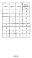
- Figure 5D is a table showing the trip voltage of a domino stage of Figures 5A-5C as a function of exemplary tuning patterns.
- Figure 6A is a circuit diagram of a tunable reference voltage generator.
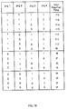
- Figures 6B and 6C are tables showing the output reference voltages and impedances, respectively, of the voltage generator of Figure 6A as a function of exemplary tuning patterns.
- Figure 7A is a circuit diagram of a tunable inverting buffer.
- Figure 7B is a table showing representative rise/fall times of the inverting buffer of Figure 7A in response to tuning patterns.
- CMOS complementary metal-oxide-semiconductor
- BCMOS bipolar-CMOS
- ECL emitter coupled logic
- FIG. 1 is a block diagram of one embodiment of tunable circuit 100 in accordance with the present invention.
- Tunable circuit 100 includes one or more tuning controllers 110, 120, ... 190 for tuning a corresponding plurality of target circuits 101, 102, ... 109.
- Each tuning controller includes one or more latches/registers and an optional decoder.
- Input data streams (A, B, C, D, E, F) is provided at the respective input nodes of six exemplary latches 112, 113, 122, 123, 192, 193.
- tuning controller 110 includes latches 112, 113 and a decoder 114, with input data streams (A, B) provided at input nodes 112a, 113a, respectively.
- Output nodes 112c, 113c of latches 112, 113, respectively, are coupled to decoder 114.
- output node 114c of decoder 114 are coupled to target circuit 101.
- target circuits 101, 102, ... 109 can be any one of exemplary target circuits described in greater detail below, or combinations thereof.
- tunable circuit 100 The operation of tunable circuit 100 is as follows. First, latches 112, 113 are loaded via input nodes 112a, 113a, respectively, with the appropriate tuning states for generating a tuning pattern which corresponds to a desired circuit parameter, e.g., a trip voltage level, for target circuit 101. Latches 112, 113 are clocked using a suitable clock signal, e.g., a "TUNING RESET & SYSTEM CLK" signal, via AND gate 111 during a reset cycle, e.g., a system-wide reset cycle or a tuning reset cycle.
- a suitable clock signal e.g., a "TUNING RESET & SYSTEM CLK" signal
- input nodes 112a, 113a receive serial input data streams (A, B) representing the desired tuning states so as to reduce the number of required input/output (I/O) pins for tunable circuit 100.
- These tuning states are made available at output nodes 112c, 113c of latches 112, 113 and provided to input nodes 114a, 114b of decoder 114, respectively.
- decoder 114 converts the tuning states into the selected tuning pattern at output node 114c.
- the tuning pattern is then provided to input node 101a of target circuit 101.
- decoder 114 may be eliminated, with latches 112, 113 directly providing the tuning pattern.
- target circuit 101 can be one of a wide variety of circuits.
- Target circuit 101 includes a tunable portion and a functional portion.
- Figures 3A, 4A, 5A, 5B, 6A and 7A show exemplary implementations of target circuits.
- target circuit 101 can also be a combination of two or more of the exemplary circuits.
- target circuit 101 is an amplification circuit 300.
- the tunable portion includes a selectable delay stage 310 and a multiplexor (MUX) 320.
- the functional portion of target circuit 101 is a sense amplifier 330 of amplification circuit 300.
- delay stage 310 is a non-inverting buffer circuit, e.g., an even number of cascaded inverters.
- MUX 320 can be replaced by fusible links or equivalents.
- a strobe signal Vin for controlling sense amplifier 330 is provided at input node 312 of delay stage 310 and also at a first input node 322 of MUX 320. Consequently, a delayed strobe signal Vind produced at output node 314 of delay stage 310 is provided to a second input node 324 of MUX 320.
- One of the two input signals provided to MUX 320 is selected by a tuning pattern signal prgl via control node 326.
- the selected output control signal Vinc at the output node 328 of MUX 320 is provided to a control node 336 of sense amplifier 330, thereby providing a delay selectable strobe signal Vinc at control node 336.
- Applications of amplification circuit 300 include a memory array where sense amplifier 330 may be shared by a column of memory cells (not shown). A pair of differential output signals from the memory column is provided as a pair of differential input signals to input nodes 332, 334 of sense amplifier 330.
- the actual data valid signal corresponding to the differential input signals provided to sense amplifier 330 is delayed by time t relative to the simulated data valid signal computed during the design stage.
- strobe signal Vn is now premature with respect to the differential input signals.
- MUX 320 is used to select the delayed strobe signal path (delayed by time d) through delay stage 310, wherein d is greater than or equal to thereby providing an appropriately delayed strobe signal for controlling sense amplifier 330.
- target circuit 101 is a signal conditioning buffer 400 and the tunable parameter is the rise and/or fall time of an output signal Vout generated at node 446 corresponding to the rise/fall time of intermediate signals Va, Vb at nodes 436a, 436b, respectively.
- Buffer 400 includes inverting stages 410a, 410b, resistive pull-up/pull-down circuits 420a, 420b, capacitive circuits 430a, 430b and an output stage 440.
- the tunable portion of buffer 400 includes pull-up circuits 420a, 420b and capacitive circuits 430a, 430b, while the function portion of buffer 400 includes inverting stages 410a, 410b and output stage 440. Note that other combinations of pull-up/pull-down and/or capacitive circuits coupled to Vdd/Vss are possible.
- Inverting stage 410a includes a pair of FETs 414a, 416a which are coupled in series between node 422a and Vss (ground). The gates of FETs 414a, 416a are coupled to input node 412a of buffer 400. Output node 418a of inverting stage 410a is coupled to node 436a of capacitive circuit 430a and also to the gate of FET 442 of output stage 440.
- inverting stage 410b includes a pair of FETs 414b, 416b which are coupled in series between node 422b and Vdd (power).
- the gates of FETs 414b, 416b are coupled to input node 412b of buffer 400.
- Output node 418b of inverting stage 410b is coupled to node 436b of capacitive circuit 430b and also to the gate of FET 444 of output stage 440.
- Resistive pull-up circuit 420a includes two pass FETs 424a, 426a and two corresponding load resistors R1, R2.
- the drains of pass FETs 424a, 426a are coupled to node 422a.
- Resistors R1, R2 are coupled between Vdd and the respective sources of FETs 424a, 426a.
- a load resistor R3 is permanently coupled between Vdd and node 422a.
- the resistive values of resistors R1, R2 and R3 are 1K ohm, 2K ohm and 4K ohm, respectively.
- resistive pull-down circuit 420b includes two pass FETs 424b, 426b and two corresponding load resistors R4, R5.
- the drains of pass FETs 424b, 426b are coupled to node 422b.
- Resistors R4, R5 are coupled between Vss and the respective sources of FETs 424b, 426b.
- a load resistor R6 is permanently coupled between Vss and node 422b.
- the resistive values of resistors R4, R5 and R6 are 1K ohm, 2K ohm and 4K ohm, respectively.
- pull-up resistive circuit 420a provides tuning capability for the fall-time of output signal Vout while complementary pull-down resistive circuit 420b provide tuning capability for the rise-time of output signal Vout.
- resistive circuits 420a, 420b each include two selectable resistors R1, R2, and R4, R5 respectively, it is apparent to one skilled in the art to modify circuits 420a, 420b by increasing or decreasing the number of resistor/FET pairs and/or to use different resistive values.
- Capacitive circuit 430a includes a pass FET 432a and a capacitive load 434a coupled in series between node 436a and Vdd.
- Capacitive circuit 430b includes a pass FET 432b and a capacitive load 434b coupled in series between node 436b and Vss. Additional capacitive circuits can also be added to increase the tuning capability of buffer 400. In some embodiments, pass FETs 432a, 432b are replaced by fusible links.
- Output stage 440 includes a pair of FETs 442, 444 coupled in series between Vdd and Vss.
- the gate of FET 442 is coupled to node 418a of inverter stage 410a and also to node Va capacitive circuit 430a, while the gate of FET 444 is coupled to node 418b of inverter stage 410b and also to node Vb of capacitive circuit 430b. Since output stage 440 is also an inverting stage, functionally, buffer 400 is a non-inverting.
- buffer 400 The operation of buffer 400 is as follows. An input signal Vin is provided to input nodes 412a, 412b of buffer 400.
- tuning signals prg1, prg2, nprg3 ( prg3 ⁇ ) are provided to the gates of pass FETs 424a, 426a and 432a, for selecting resistors R1, R2 and capacitive load 434a, respectively.
- tuning signals nprgl ( prg1 ⁇ ), nprg2 ( prg2 ⁇ ), prg3 are provided to the gates of pass FETs 424b, 426b and 432b, for selecting resistors R4, R5 and capacitive load 434b, respectively.
- the rise/fall times of output signal Vout produced by buffer 400 is tuned by selectively engaging/disengaging one or more of resistor pairs R1, R4, and R2, R5 and capacitive load pair 434a, 434b.
- Figure 4B is a table showing representative rise/fall times of signals Va, Vb at nodes 436a, 436b, respectively, in response to the respective tuning patterns formed by tuning signals prg1, prg2, prg3. For example, by selecting both resistor pairs R1, R4, and R2, R5, the resistance of pull-up circuit 420a and the resistance of pull-down circuit 420b are reduced to a minimal level thereby increasing the speed of the rise time of output signal Vout. Similarly, by deselecting capacitive load pair 434a, 434b, the rise time of output signal Vout is speeded up.
- the rise time of output signal Vout can be slowed down.
- 434a, 434b selectable load resistors R1, R2, R4, R5 and capacitive loads 434a, 434b can also be used to control the power consumption of buffer 400 by using suitable tuning patterns provided to buffer 400 via pass FETs 424a, 426a, 424b, 426b, and pass FETs 432a, 432b, respectively.
- target circuit 101 is a "domino" logic circuit 500 having a tunable trip threshold voltage Vtrip.
- circuit 500 includes two domino stages 501, 502 coupled in series.
- First domino stage 501 includes first logic stage 510, a first inverter 520 and a first pull-up circuit 530.
- Second domino stage 502 includes a second logic stage 540, a second inverter 550 and a second pull-up circuit 560. Note that additional "domino" logic stages can be added to circuit 500 depending on the application.
- the output node of first logic stage 510 is coupled to the input node of first inverter 520.
- Inverter 520 is coupled to Vdd via first pull-up circuit 530.
- the output node of first inverter 520 is coupled to the input node of second logic stage 540.
- the output node of second logic stage 540 is coupled to the input node of second inverter 550.
- Inverter 550 is coupled to Vdd via second pull-up circuit 560.
- Figure 5C an exemplary CMOS implementation of exemplary circuit 500 of Figure 5B illustrates first and second domino stages 501, 502 in detail.
- First logic stage, NAND gate 510 includes a PMOS FET 511 and three NMOS FETs 512, 513, 514 coupled in series between Vdd and Vss.
- a system clock signal CLK is provided at gate 511a of FET 511.
- the junction formed by the drains of FETs 511,512 is coupled to an output node 518.
- First inverter 520 includes a PMOS FET 521 and an NMOS FET 522 coupled in series between Vdd and Vss.
- An output node 526 is formed at the junction of the drains of FETs 521, 522.
- First pull-up circuit 530 includes PMOS FETs 531, 532, 533, with the drain of FET 532 coupled to input node 523 of inverter 520, the source of FET 533 coupled to the drains of both FETs 531, 532, and the sources of FETs 531, 532 coupled to Vdd.
- the gate of FET 533 is also coupled to the output node 526 of inverter 520.
- Second logic stage 540 includes PMOS FET 541 and NMOS FETs 542, 543, 544, 545.
- System clock signal CLK is provided at gates of FETs 541 and 545.
- FETs 541, 542, 543, 545 are coupled in series between Vdd and Vss.
- FETs 543 and 544 coupled to each other in parallel.
- the junction formed by the drains of FETs 541, 542 is coupled to input node 553 of second inverter 550.
- Second inverter 550 includes a PMOS FET 551 and an NMOS FET 552 coupled in series between Vdd and Vss.
- An output node 556 is formed at the junction of the drains of FETs 551, 552 is coupled to output node Vout.
- Second pull-up circuit 560 includes PMOS FETs 561, 562, 563, with the drain of FET 563 coupled to input node 553 of inverter 550, the source of FET 563 coupled to the drains of both FETs 561, 562, and the sources of FETs 561, 562 coupled to Vdd.
- the gate of FET 563 is also coupled to the output node 556 of inverter 550.
- the operation of domino stages 501, 502 is as follows.
- Input logic signals A, B and C are provided at gates 512a, 513a, 514a of FETs 512, 513, 514, respectively.
- output node 518 of NAND gate 510 provides a logical NAND of input signals A, B, C, i.e., A*B*C ⁇ , to input node 523 of inverter stage 520.
- the "D” logic signal is provided at the gate of FET 542.
- input logic signals E and F are provided at the gates of FETs 543, 544.
- tuning pattern signals prg1, prg2 are provided to the respective gates of FETs 531, 532 thereby enabling a designer to adjust the threshold trip voltage Vtrip, of first domino stage 501.
- tuning pattern signals prg3, prg4 are provided to the respective gates of FETs 561, 562 control the threshold trip voltage Vtrip of second domino stage 502.
- tuning pattern signals prg1, prg2. prg3 and prg4 can be used to vary the Vtrip of output signal Vout generated by circuit 500.
- FIG. 5D is a table illustrating exemplary trip voltage Vtrip of first domino stage 501 as a function of tuning pattern signals prgl, prg2.
- different combinations of tuning pattern signals prgl, prg2 produces Vtrip voltage levels ranging between 0.5 volts and 1.3 volts.
- pull-up circuits 530, 560 are similar in operation, tuning signals prg3, prg4 will vary the Vtrip of second domino stage 502 in a similar manner.
- Other voltage ranges and intervals are possible by adding additional pull-up circuit(s) to domino logic circuit 500, thereby extending the Vtrip voltage range and granularity of voltage intervals.
- FIG. 6A is a circuit diagram of another embodiment of targeted circuit 101.
- targeted circuit 101 is a reference voltage generator 600 and the tunable parameter is a reference voltage Vref produced by generator 600.
- Voltage generator 600 includes a voltage divider 610, first and second pull-up circuits 620, 630, and first and second pull-down circuits 640, 650.
- Functional portion includes voltage divider 610 while tunable portion includes circuits 620, 630, 640, 650.
- P-channel FETs are described in this embodiment, it will be apparent to one skilled in the art to substitute N-channel FETs in place of the P-channel FETs with the appropriate modifications.
- Voltage divider 610 includes a pair of FETs 612, 614 coupled in series between Vdd and Vss.
- the gate and drain of FET 612 and the source of FET 614 are coupled to output node 690.
- the gate and drain of FET 614 are coupled to Vss.
- First pull-up circuit 620 includes FETs 622, 624 coupled in series between Vdd and output node 690. The gate of FET 624 is also coupled to output node 690.
- First pull-down circuit 640 includes an FET 642 whose source and drain are coupled to output node 690 and Vss, respectively.
- second pull-up circuit 630 similar in structure to first pull-up circuit 620, provides additional voltage range for reference voltage Vref. Additional pull-up circuits can be added to further increase the range of voltage Vref.
- second pull-down circuit 650 similar in structure to first pull-down circuit 640 provide additional voltage range for reference voltage Vref. Additional pull-down circuits can be added to further increase the range of voltage Vref.
- Tuning of voltage generator 600 is accomplished by tuning pattern signals prg1, prg2, prg3, prg4 provided at the gates of FETs 622, 632, 642, 652, respectively.
- tuning pattern signals prg1, prg2, prg3, prg4 provided at the gates of FETs 622, 632, 642, 652, respectively.
- pull-up circuits 620, 630 reference voltage Vref can be incrementally increased.
- pull-down circuits 640, 650 reference voltage can be incrementally decreased.
- Figure 6B is a table showing exemplary voltages levels of reference Vref in response to tuning pattern signals prg1, prg2, prg3 and prg4, wherein Vdd is 2.5 volts.
- Tuning pattern signals prg1, prg2, prg3, prg4 can also be used to control the impedance of voltage generator 600.
- Figure 6C show exemplary impedances of generator 600 in response to tuning pattern signals prg1, prg2, prg3 and prg4.
- target 101 is an inverting buffer 700 including an inverting stage 710, first and second resistive stages 720, 730, capacitive circuits 740, 750, 760 and 770.
- Resistive stage 720 includes a P-channel FET 722, an N-channel FET 724 and a first resistor R1 coupled in parallel.
- resistive stage 730 includes a P-channel FET 732, an N-channel FET 734 and a second resistor R2 coupled in parallel.
- Each of capacitive circuits 740, 750 include a P-channel FET and a capacitive load coupled in series between Vdd and output node 790, while each of capacitive circuits 760, 770 include an N-channel FET and a capacitive load coupled in series between output node 790 and Vss.
- resistive stages 720, 730 provide coarse rise/fall time control for buffer 700.
- Capacitive circuits 740, 750, 760, 770 are functionally similar to capacitive circuits in the embodiment of Figure 4A, and provide fine control for either rise/fall-time and consequently power consumption of buffer 700.
- Tuning pattern signals prg1, prg2, nprg3 ( prg3 ⁇ ), nprg4 ( prg4 ⁇ ) are provided to the gate of pass FETs 722, 732, 742, 752.
- tuning pattern signals nprg1 ( prg1 ⁇ ), nprg2 ( prg2 ⁇ ), prg3, prg4 are provided to the gates of pass FETs 724, 734, 762, 772.
- Resistor R1 of resistive stage 720 is bypassed by turning on both FETs 722 and 724.
- resistor R2 of resistive stage 730 is bypassed by turning on both FETs 732 and 734.
- Capacitive circuits 740, 750, 760, 770 are selected by turning on FETs 742, 752, 762, 772, respectively.
- Figure 7B is a table showing exemplary rise/fall times of output signal Vout generated by buffer 700 as a function of tuning patterns. In this example, rise/fall times of output signal Vout t1 ⁇ t2 ⁇ t3 ... ⁇ t16.
Landscapes
- Engineering & Computer Science (AREA)
- Physics & Mathematics (AREA)
- Computer Hardware Design (AREA)
- General Engineering & Computer Science (AREA)
- Computing Systems (AREA)
- Mathematical Physics (AREA)
- General Physics & Mathematics (AREA)
- Semiconductor Integrated Circuits (AREA)
- Logic Circuits (AREA)
Applications Claiming Priority (2)
| Application Number | Priority Date | Filing Date | Title |
|---|---|---|---|
| US08/499,716 US5729158A (en) | 1995-07-07 | 1995-07-07 | Parametric tuning of an integrated circuit after fabrication |
| US499716 | 1995-07-07 |
Publications (2)
| Publication Number | Publication Date |
|---|---|
| EP0752677A2 true EP0752677A2 (fr) | 1997-01-08 |
| EP0752677A3 EP0752677A3 (fr) | 1999-04-21 |
Family
ID=23986405
Family Applications (1)
| Application Number | Title | Priority Date | Filing Date |
|---|---|---|---|
| EP96304968A Withdrawn EP0752677A3 (fr) | 1995-07-07 | 1996-07-05 | Syntonisation paramétrique d'un circuit intégré après sa fabrication |
Country Status (3)
| Country | Link |
|---|---|
| US (4) | US5729158A (fr) |
| EP (1) | EP0752677A3 (fr) |
| JP (1) | JPH09223955A (fr) |
Cited By (11)
| Publication number | Priority date | Publication date | Assignee | Title |
|---|---|---|---|---|
| EP0913942A2 (fr) * | 1997-10-29 | 1999-05-06 | Hewlett-Packard Company | Circuit intégré dont les caractéristiques des bornes de sortie sont spécifiques à une application et méthode de fonctionnement |
| EP0926825A2 (fr) * | 1997-12-24 | 1999-06-30 | Nec Corporation | Circuit statique de verrouillage et circuit logique statique |
| EP0959564A1 (fr) * | 1998-05-22 | 1999-11-24 | Lucent Technologies Inc. | Dispositif résistif à commande linéaire |
| EP0970564A1 (fr) * | 1997-03-24 | 2000-01-12 | Intel Corporation | Procede et appareil de compensation de la vitesse de balayage et de l'impedance de circuits tampons |
| GB2340684A (en) * | 1998-08-10 | 2000-02-23 | Sgs Thomson Microelectronics | A CMOS inverter with a process, voltage and temperature-insensitive switching threshold voltage |
| WO2002003553A1 (fr) * | 2000-06-30 | 2002-01-10 | Intel Corporation | Tampon a force d'entrainement compensatrice |
| US6606705B1 (en) | 1999-09-15 | 2003-08-12 | Intel Corporation | Method and apparatus for configuring an I/O buffer having an initialized default signaling level to operate at a sampled external circuit signaling level |
| US6665761B1 (en) | 1999-07-28 | 2003-12-16 | Unisys Corporation | Method and apparatus for routing interrupts in a clustered multiprocessor system |
| US6687818B1 (en) | 1999-07-28 | 2004-02-03 | Unisys Corporation | Method and apparatus for initiating execution of an application processor in a clustered multiprocessor system |
| US7844747B2 (en) * | 2002-06-05 | 2010-11-30 | Stmicroelectronics, Inc. | Performance tuning using encoded performance parameter information |
| US9600623B1 (en) | 2015-09-22 | 2017-03-21 | International Business Machines Corporation | Scheduling simultaneous optimization of multiple very-large-scale-integration designs |
Families Citing this family (18)
| Publication number | Priority date | Publication date | Assignee | Title |
|---|---|---|---|---|
| US5729158A (en) * | 1995-07-07 | 1998-03-17 | Sun Microsystems, Inc. | Parametric tuning of an integrated circuit after fabrication |
| US5960405A (en) * | 1997-02-05 | 1999-09-28 | Fox Enterprises, Inc. | Worldwide marketing logistics network including strategically located centers for frequency programming crystal oscillators to customer specification |
| US5952890A (en) | 1997-02-05 | 1999-09-14 | Fox Enterprises, Inc. | Crystal oscillator programmable with frequency-defining parameters |
| US6028462A (en) * | 1997-08-22 | 2000-02-22 | Lsi Logic Corporation | Tunable delay for very high speed |
| US6008680A (en) * | 1997-08-27 | 1999-12-28 | Lsi Logic Corporation | Continuously adjustable delay-locked loop |
| US6330182B1 (en) | 1998-09-23 | 2001-12-11 | Intel Corporation | Method for evaluating soft error immunity of CMOS circuits |
| US6087849A (en) * | 1998-09-23 | 2000-07-11 | Intel Corporation | Soft error immunity in CMOS circuits with large shared diffusion areas |
| US6515533B1 (en) * | 1998-09-29 | 2003-02-04 | Agere Systems Inc. | Multi-input comparator |
| JP3849835B2 (ja) * | 1999-06-23 | 2006-11-22 | 株式会社ルネサステクノロジ | 半導体集積回路装置 |
| US6411147B1 (en) * | 2000-10-11 | 2002-06-25 | General Electric Company | System and method for grouped gating control logic |
| US6529057B2 (en) * | 2001-04-12 | 2003-03-04 | Sun Microsystems, Inc. | Stretching, shortening, and/or removing a clock cycle |
| WO2003088289A2 (fr) * | 2002-04-12 | 2003-10-23 | University Of Rochester | Circuits logiques domino a double tension de seuil et faible balancement |
| US7112979B2 (en) * | 2002-10-23 | 2006-09-26 | Intel Corporation | Testing arrangement to distribute integrated circuits |
| US6927605B2 (en) * | 2003-11-07 | 2005-08-09 | Hewlett-Packard Development Company, L.P. | System and method for dynamically varying a clock signal |
| TWI267857B (en) * | 2003-12-19 | 2006-12-01 | Hynix Semiconductor Inc | Apparatus for adjusting slew rate in semiconductor memory device and method therefor |
| EP1884788B1 (fr) * | 2006-07-27 | 2010-05-19 | STMicroelectronics Asia Pacific Pte Ltd. | Arrangement de paramètres opératoires dans les dispositifs électroniques basés sur les configurations des corrections |
| US20090146144A1 (en) * | 2007-12-10 | 2009-06-11 | Broadcom Corporation | Method and system supporting production of a semiconductor device using a plurality of fabrication processes |
| US9548726B1 (en) * | 2015-02-13 | 2017-01-17 | Inphi Corporation | Slew-rate control and waveshape adjusted drivers for improving signal integrity on multi-loads transmission line interconnects |
Citations (6)
| Publication number | Priority date | Publication date | Assignee | Title |
|---|---|---|---|---|
| US5065055A (en) * | 1990-12-20 | 1991-11-12 | Sun Microsystems, Inc. | Method and apparatus for high-speed bi-CMOS differential amplifier with controlled output voltage swing |
| EP0463316A1 (fr) * | 1990-06-07 | 1992-01-02 | International Business Machines Corporation | Etage d'attaque auto-ajustable pour adaptation d'impédance |
| US5162672A (en) * | 1990-12-24 | 1992-11-10 | Motorola, Inc. | Data processor having an output terminal with selectable output impedances |
| EP0520687A1 (fr) * | 1991-06-28 | 1992-12-30 | AT&T Corp. | Dimensionnement contrôlé numériquement de la taille d'un composant |
| EP0611053A2 (fr) * | 1993-02-08 | 1994-08-17 | Advanced Micro Devices, Inc. | Circuits tampon |
| US5361042A (en) * | 1993-06-18 | 1994-11-01 | Digital Equipment Corporation | Compensated offset voltage, low gain, high bandwidth, full swing, wide common mode range, CMOS differential voltage amplifier |
Family Cites Families (15)
| Publication number | Priority date | Publication date | Assignee | Title |
|---|---|---|---|---|
| JPS5942690A (ja) * | 1982-09-03 | 1984-03-09 | Toshiba Corp | 半導体記憶装置 |
| US4737670A (en) * | 1984-11-09 | 1988-04-12 | Lsi Logic Corporation | Delay control circuit |
| JPS6429925U (fr) * | 1987-08-13 | 1989-02-22 | ||
| FR2666183B1 (fr) * | 1990-08-23 | 1992-11-06 | Bull Sa | Circuit a constante de temps reglable et application a un circuit a retard reglable. |
| US5204836A (en) * | 1990-10-30 | 1993-04-20 | Sun Microsystems, Inc. | Method and apparatus for implementing redundancy in parallel memory structures |
| US5121014A (en) * | 1991-03-05 | 1992-06-09 | Vlsi Technology, Inc. | CMOS delay circuit with controllable delay |
| US5153450A (en) * | 1991-07-16 | 1992-10-06 | Samsung Semiconductor, Inc. | Programmable output drive circuit |
| US5220216A (en) * | 1992-01-02 | 1993-06-15 | Woo Ann K | Programmable driving power of a CMOS gate |
| JP2657019B2 (ja) * | 1992-03-13 | 1997-09-24 | 三菱電機株式会社 | Mosトランジスタ出力回路 |
| FI92120C (fi) * | 1992-04-15 | 1994-09-26 | Nokia Mobile Phones Ltd | Jänniteohjattu oskillaattori |
| JP2576366B2 (ja) * | 1993-06-23 | 1997-01-29 | 日本電気株式会社 | 可変遅延バッファ回路 |
| US5471663A (en) * | 1993-07-01 | 1995-11-28 | Motorola, Inc. | Expanded microcomputer system for controlling radio frequency interference |
| KR960007258B1 (ko) * | 1993-09-03 | 1996-05-29 | 금성일렉트론 주식회사 | 출력 버퍼 |
| US5395113A (en) * | 1994-02-24 | 1995-03-07 | Antonious; Anthony J. | Iron type golf club with improved weight configuration |
| US5729158A (en) * | 1995-07-07 | 1998-03-17 | Sun Microsystems, Inc. | Parametric tuning of an integrated circuit after fabrication |
-
1995
- 1995-07-07 US US08/499,716 patent/US5729158A/en not_active Expired - Lifetime
-
1996
- 1996-07-05 EP EP96304968A patent/EP0752677A3/fr not_active Withdrawn
- 1996-07-08 JP JP8195280A patent/JPH09223955A/ja active Pending
-
1997
- 1997-09-11 US US08/927,976 patent/US5973541A/en not_active Expired - Lifetime
- 1997-09-11 US US08/927,237 patent/US6157236A/en not_active Expired - Fee Related
- 1997-09-11 US US08/956,624 patent/US6140856A/en not_active Expired - Lifetime
Patent Citations (6)
| Publication number | Priority date | Publication date | Assignee | Title |
|---|---|---|---|---|
| EP0463316A1 (fr) * | 1990-06-07 | 1992-01-02 | International Business Machines Corporation | Etage d'attaque auto-ajustable pour adaptation d'impédance |
| US5065055A (en) * | 1990-12-20 | 1991-11-12 | Sun Microsystems, Inc. | Method and apparatus for high-speed bi-CMOS differential amplifier with controlled output voltage swing |
| US5162672A (en) * | 1990-12-24 | 1992-11-10 | Motorola, Inc. | Data processor having an output terminal with selectable output impedances |
| EP0520687A1 (fr) * | 1991-06-28 | 1992-12-30 | AT&T Corp. | Dimensionnement contrôlé numériquement de la taille d'un composant |
| EP0611053A2 (fr) * | 1993-02-08 | 1994-08-17 | Advanced Micro Devices, Inc. | Circuits tampon |
| US5361042A (en) * | 1993-06-18 | 1994-11-01 | Digital Equipment Corporation | Compensated offset voltage, low gain, high bandwidth, full swing, wide common mode range, CMOS differential voltage amplifier |
Cited By (18)
| Publication number | Priority date | Publication date | Assignee | Title |
|---|---|---|---|---|
| EP0970564A4 (fr) * | 1997-03-24 | 2000-11-02 | Intel Corp | Procede et appareil de compensation de la vitesse de balayage et de l'impedance de circuits tampons |
| EP0970564A1 (fr) * | 1997-03-24 | 2000-01-12 | Intel Corporation | Procede et appareil de compensation de la vitesse de balayage et de l'impedance de circuits tampons |
| EP0913942A2 (fr) * | 1997-10-29 | 1999-05-06 | Hewlett-Packard Company | Circuit intégré dont les caractéristiques des bornes de sortie sont spécifiques à une application et méthode de fonctionnement |
| EP0913942A3 (fr) * | 1997-10-29 | 2000-02-02 | Hewlett-Packard Company | Circuit intégré dont les caractéristiques des bornes de sortie sont spécifiques à une application et méthode de fonctionnement |
| EP0926825A2 (fr) * | 1997-12-24 | 1999-06-30 | Nec Corporation | Circuit statique de verrouillage et circuit logique statique |
| EP0926825A3 (fr) * | 1997-12-24 | 1999-08-04 | Nec Corporation | Circuit statique de verrouillage et circuit logique statique |
| US6326821B1 (en) | 1998-05-22 | 2001-12-04 | Agere Systems Guardian Corp. | Linearly-controlled resistive element apparatus |
| EP0959564A1 (fr) * | 1998-05-22 | 1999-11-24 | Lucent Technologies Inc. | Dispositif résistif à commande linéaire |
| GB2340684A (en) * | 1998-08-10 | 2000-02-23 | Sgs Thomson Microelectronics | A CMOS inverter with a process, voltage and temperature-insensitive switching threshold voltage |
| US6665761B1 (en) | 1999-07-28 | 2003-12-16 | Unisys Corporation | Method and apparatus for routing interrupts in a clustered multiprocessor system |
| US6687818B1 (en) | 1999-07-28 | 2004-02-03 | Unisys Corporation | Method and apparatus for initiating execution of an application processor in a clustered multiprocessor system |
| US6606705B1 (en) | 1999-09-15 | 2003-08-12 | Intel Corporation | Method and apparatus for configuring an I/O buffer having an initialized default signaling level to operate at a sampled external circuit signaling level |
| WO2002003553A1 (fr) * | 2000-06-30 | 2002-01-10 | Intel Corporation | Tampon a force d'entrainement compensatrice |
| US6624662B1 (en) | 2000-06-30 | 2003-09-23 | Intel Corporation | Buffer with compensating drive strength |
| US7844747B2 (en) * | 2002-06-05 | 2010-11-30 | Stmicroelectronics, Inc. | Performance tuning using encoded performance parameter information |
| US9600623B1 (en) | 2015-09-22 | 2017-03-21 | International Business Machines Corporation | Scheduling simultaneous optimization of multiple very-large-scale-integration designs |
| US10083268B2 (en) | 2015-09-22 | 2018-09-25 | International Business Machines Corporation | Scheduling simultaneous optimization of multiple very-large-scale-integration designs |
| US10789400B2 (en) | 2015-09-22 | 2020-09-29 | International Business Machines Corporation | Scheduling simultaneous optimization of multiple very-large-scale-integration designs |
Also Published As
| Publication number | Publication date |
|---|---|
| EP0752677A3 (fr) | 1999-04-21 |
| JPH09223955A (ja) | 1997-08-26 |
| US5973541A (en) | 1999-10-26 |
| US6140856A (en) | 2000-10-31 |
| US6157236A (en) | 2000-12-05 |
| US5729158A (en) | 1998-03-17 |
Similar Documents
| Publication | Publication Date | Title |
|---|---|---|
| US6140856A (en) | Parametric tuning of an intergrated circuit after fabrication | |
| US8115530B2 (en) | Robust time borrowing pulse latches | |
| US8253463B1 (en) | Pulse width control circuitry | |
| US9536038B1 (en) | Method and algorithm for functional critical paths selection and critical path sensors and controller insertion | |
| US7675317B2 (en) | Integrated circuits with adjustable body bias and power supply circuitry | |
| US8222921B2 (en) | Configurable time borrowing flip-flops | |
| US6593792B2 (en) | Buffer circuit block and design method of semiconductor integrated circuit by using the same | |
| US5418473A (en) | Single event upset immune logic family | |
| US6239616B1 (en) | Programmable delay element | |
| US7466582B2 (en) | Voltage controlled static random access memory | |
| US4639615A (en) | Trimmable loading elements to control clock skew | |
| US20030115560A1 (en) | Method for controlling critical circuits in the design of integrated circuits | |
| US5341046A (en) | Threshold controlled input circuit for an integrated circuit | |
| US6260181B1 (en) | Integrated circuit and the design method thereof | |
| US7382170B2 (en) | Programmable delay circuit having reduced insertion delay | |
| US7644385B1 (en) | Programmable logic device with performance variation compensation | |
| US6011425A (en) | CMOS offset trimming circuit and offset generation circuit | |
| US7352252B2 (en) | Circuit and method to measure threshold voltage distributions in SRAM devices | |
| JP5614781B2 (ja) | セル・ライブラリから選択された信号スキュー調整セルを備えた集積回路 | |
| US6215336B1 (en) | Reference type input first stage circuit in a semiconductor integrated circuit | |
| US6502223B1 (en) | Method for simulating noise on the input of a static gate and determining noise on the output | |
| JP4117995B2 (ja) | 半導体装置 | |
| US20040221211A1 (en) | Individually adjustable back-bias technique | |
| US6462581B1 (en) | Programmable timing boundary in dynamic circuits | |
| US6496031B1 (en) | Method for calculating the P/N ratio of a static gate based on input voltages |
Legal Events
| Date | Code | Title | Description |
|---|---|---|---|
| PUAI | Public reference made under article 153(3) epc to a published international application that has entered the european phase |
Free format text: ORIGINAL CODE: 0009012 |
|
| AK | Designated contracting states |
Kind code of ref document: A2 Designated state(s): DE GB |
|
| PUAL | Search report despatched |
Free format text: ORIGINAL CODE: 0009013 |
|
| AK | Designated contracting states |
Kind code of ref document: A3 Designated state(s): DE GB |
|
| STAA | Information on the status of an ep patent application or granted ep patent |
Free format text: STATUS: THE APPLICATION IS DEEMED TO BE WITHDRAWN |
|
| 18D | Application deemed to be withdrawn |
Effective date: 19990202 |