EP0752575B1 - Wägezelle - Google Patents
Wägezelle Download PDFInfo
- Publication number
- EP0752575B1 EP0752575B1 EP96107329A EP96107329A EP0752575B1 EP 0752575 B1 EP0752575 B1 EP 0752575B1 EP 96107329 A EP96107329 A EP 96107329A EP 96107329 A EP96107329 A EP 96107329A EP 0752575 B1 EP0752575 B1 EP 0752575B1
- Authority
- EP
- European Patent Office
- Prior art keywords
- load cell
- cell according
- strain gauges
- cover
- force introduction
- Prior art date
- Legal status (The legal status is an assumption and is not a legal conclusion. Google has not performed a legal analysis and makes no representation as to the accuracy of the status listed.)
- Expired - Lifetime
Links
Images

Classifications
-
- G—PHYSICS
- G01—MEASURING; TESTING
- G01L—MEASURING FORCE, STRESS, TORQUE, WORK, MECHANICAL POWER, MECHANICAL EFFICIENCY, OR FLUID PRESSURE
- G01L1/00—Measuring force or stress, in general
- G01L1/20—Measuring force or stress, in general by measuring variations in ohmic resistance of solid materials or of electrically-conductive fluids; by making use of electrokinetic cells, i.e. liquid-containing cells wherein an electrical potential is produced or varied upon the application of stress
- G01L1/22—Measuring force or stress, in general by measuring variations in ohmic resistance of solid materials or of electrically-conductive fluids; by making use of electrokinetic cells, i.e. liquid-containing cells wherein an electrical potential is produced or varied upon the application of stress using resistance strain gauges
- G01L1/2206—Special supports with preselected places to mount the resistance strain gauges; Mounting of supports
- G01L1/2218—Special supports with preselected places to mount the resistance strain gauges; Mounting of supports the supports being of the column type, e.g. cylindric, adapted for measuring a force along a single direction
-
- G—PHYSICS
- G01—MEASURING; TESTING
- G01G—WEIGHING
- G01G3/00—Weighing apparatus characterised by the use of elastically-deformable members, e.g. spring balances
- G01G3/12—Weighing apparatus characterised by the use of elastically-deformable members, e.g. spring balances wherein the weighing element is in the form of a solid body stressed by pressure or tension during weighing
- G01G3/14—Weighing apparatus characterised by the use of elastically-deformable members, e.g. spring balances wherein the weighing element is in the form of a solid body stressed by pressure or tension during weighing measuring variations of electrical resistance
- G01G3/1402—Special supports with preselected places to mount the resistance strain gauges; Mounting of supports
- G01G3/1408—Special supports with preselected places to mount the resistance strain gauges; Mounting of supports the supports being of the column type, e.g. cylindric
Definitions
- the invention relates to a rod-shaped load cell according to the Preamble of claim 1.
- Such a load cell is known from EP 0 315 846 B1. It is a dumbbell-shaped rod with a slim center part and much thicker end areas, the strain gauges including sensors for linearization of the measured values and for temperature compensation are arranged approximately in the middle of the center part.
- the known load cell is self-righting, i.e. the end Force application surfaces are designed so that inevitably a restoring moment is generated when the load cell is deflected from a vertical position.
- the entire center part is covered by a corrugated tube that ends with is connected to the thicker end areas of the load cell.
- a transverse bore is provided in an end region, the through thinner holes with the surface of the center part is connected and for receiving the outgoing from the sensors Cable is determined.
- This known load cell is very complex to manufacture and expensive and therefore not competitive in many applications, where it mainly relies on a sturdy construction and less on the highest measuring sensitivity and accuracy arrives.
- the cover is by means of a corrugated pipe technically complicated because they can only be realized is when the components to be connected are dimensionally accurate are coordinated.
- a force transducer is known from EP 0 307 998 A2, which via an axially extending cylindrical compression body has rounded ends at the ends of the force input and force transmission are arranged. Approximately axially in the middle of the The upsetting body is a large one transverse to the axial direction Through hole provided by two opposite arranged disc-shaped carrier plates sealed is. Thereby are on the inward facing flat surface Strain gauges for each carrier disc using the layering technique applied.
- the carrier disks are welded or welded Solder connection parallel to each other in the two opposite Fixed holes and close them, see above that the strain gauges are protected against corrosion.
- There the force to be measured mainly via the carrier plates is transferred depends on the durability and tightness of the Carrier plates strongly depend on the quality of the welded or soldered connection from which the carrier plates are connected to the compression body are.
- a load measuring cell is known from EP 0 107 966 B1, in which the strain gauges using a glued aluminum composite film are covered.
- Such covers have practically no influence on the spring characteristic of the load cell, but are only moisture-proof if the edges Cut edges of the aluminum composite film treated additionally, for example covered with a vapor-deposited aluminum seam become. This also makes this type of coverage pretty expensive, apart from the fact that it protects against mechanical damage is sensitive and therefore for many applications is out of the question. In addition, the Leading out the cables trouble.
- the invention has for its object a load cell create the kind mentioned above, which are simply constructed and is comparatively cheap to manufacture and in particular a safe and technically easy to implement cover which enables areas equipped with strain gauges.
- metallic cover Unlike the well-known aluminum composite film, it can metallic cover to any type of mechanical stress be adjusted so that for the respective application a sufficiently robust securing of the strain gauges can be achieved. Leave such metallic covers easy to manufacture and easy on the respective geometry adapt the load cell or the strain gauge arrangement. They can also be easily designed so that they only have one have little influence on the spring characteristic of the load cell or that their influence can be compensated for relatively easily. The shape of the cover and its connection to the load cell can be selected so that adverse repercussions are practically excluded.
- the cover can be connected to the load cell by Welding, especially laser welding, by soldering or gluing respectively. In all cases, a moisture-tight seal the areas with strain gauges reached without significantly affects the mechanical properties of the load cell become.
- the rod-shaped load cell itself can be between the end-face force application surfaces as a simple turned part with essentially the same, preferably uniform Cross section are produced and so the demand for meet lower manufacturing costs.
- a polygonal, e.g. square cross section the rod-shaped load cell or areas of the rod-shaped Load cell can be provided.
- the load cell is approximately in the middle between the ends Force application surfaces perpendicular to their longitudinal axis has a hole and that the strain gauges on the Bore wall are attached. So that is in the load cell in easily created a weakened cross-sectional area, the best for attaching the strain gauges suitable is. You also win a room in which the strain gauges against external mechanical destruction are largely secured. Suitable for closing the hole simply shaped sheets such as deep-drawn or pressed Sheets.
- the bore can also be easily done with end sections be provided of larger diameter, the circular end faces between larger and smaller Diameter as a support for a circular disk-shaped cover serve and a particularly good and easy to implement Allow connection between load cell and cover.
- the Shaping can be done by simple machining and contributes to the fact that the load cell is manufactured inexpensively can be.
- the load cell is approximately in the middle between the ends Force introduction surfaces diametrically opposite recesses has, on the base surfaces of the strain gauges are attached and that the recesses are closed by covers are that overlap these and with the Load cell are connected on the edge.
- dimensioning the Recesses by size and depth can be any desired cross-sectional weakening the load cell can be reached, also here just a simple, inexpensive milling and / or drilling process is required for manufacture.
- Can use as cover flat or preformed sheet metal sections can be used cover the recess and again very comfortably at the edge to be connected to the load cell.
- the idea of the invention can also be found in a Apply the cross-section of the weakened load cell using the Strain gauges simply on the preferably cylindrical Shell surface applied and with a lid-like edge cover connected to the load cell are completed.
- the load cell requires practically none machining to create areas on those the strain gauges can be attached.
- By appropriate Design of the covers can be ensured that the strain gauges are secured without the Covers come into contact with the strain gauges.
- the load cell can have a fixed one Have holder cooperating annular locking washer, which is attached to the load cell.
- the idea of the invention can of course also be used Use load cells in which at least one of the force application surfaces is just trained.
- the force application area can also be used with facilities e.g. in the form of thread devices be provided via a connection of the load cell with force introduction components, for example for application a tensile load is possible.
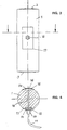
- the rod-like load cell 1 shown in FIGS. 1 and 2 has a circular cylindrical shape with spherical ends trained force application surfaces 2 and 3. However, you can also a polygonal, for example square, cross section exhibit. The adjacent end areas are set apart from the middle section by a smaller diameter.
- the load cell 1 has a bore 4 perpendicular to it Longitudinal axis.
- the end portions 5 of the bore 4 have something larger diameter, whereby circular end faces 6 formed for the support of disk-shaped covers 7, 8 are.
- the strain gauges 9 are inside the bore 4 arranged.
- the cover 8 is with a screw connection 10 provided for the implementation of a cable 11 through which Strain gauges 9 can be connected to an evaluation device.
- the covers 7, 8 are sealed in the bore by welding 4 attached.
- the load cell 1 To prevent the load cell 1 from rotating about its longitudinal axis is near the lower force introduction surface 3 with the Load cell 1 is provided in the form of an annular disk 12, which has an edge recess 13, in the assembled state the load cell 1 engages a stationary holder. Thereby is prevented that the load cell 1 can rotate and the Cable connection is damaged.
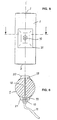
- the load cell is 1 continuously between the force introduction surfaces 2 and 3 circular cylindrical design. It shows two diametrically arranged recesses 14 on the bottom surfaces 15 strain gauges are attached.
- the recesses 14 are from Covers 16, 17 that arch the cylinder shape of the load cell 1 adapted and welded to their edges with this are.
- the cover 17 has a screw connection 10 for the Implementation of a cable 11.
- the recesses 14 are through a thin transverse bore 18 penetrating the load cell 1 with one another connected by an internal cable connection is led.
- the embodiment according to Figures 5 and 6 is special simply designed and therefore cheaper to manufacture.
- the between the force introduction surfaces 2 and 3 at the end continuous circular cylindrical load cell 1 requires mechanical Shaping only one transverse bore 18 because the areas 19 for the attachment of the strain gauges diametrically on the outer lateral surface of the load cell 1 are provided.
- the covers 20, 21 are hood-shaped and on its edges connected to the load cell 1 by welding.
- the cover 21 contains a screw connection 10 for the Implementation of a cable 11, which also via the transverse bore 18 connected to the strain gauges under the other cover is.
- load cells of FIGS. 3 can also be to 6 a safeguard against rotation about the longitudinal axis or a polygonal, e.g. square cross section can be provided.
- the load cells shown in Figures 1 to 6 are for determines the introduction of compressive forces.
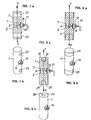
- An advantageous one Application of the invention to load cells for introducing tensile forces show the embodiments shown in Figures 7 to 9.
- the load cells 1 from a circular cylindrical rod, which is analog 1 to the cylinder axis to the load cell according to FIG has vertical bore 4 in which the strain gauges 9 are arranged.
- the bore 4 is with covers 7, 8 closed, the cover 8 a screw terminal 10 for carrying a cable 11.
- the force introduction surfaces are formed by transverse bores 22, 23 in the End sections of the load cells 1 parallel to each other and parallel are arranged to bore 8; however, they can too be perpendicular to the hole.
- the transverse bores 22, 23 are used to receive pins that the tensile forces F on the Transfer load cell 1.
- FIG. 8 shows an embodiment of the load cell 1 that for the introduction of force in the end faces 24, 25 coaxially Cylinder axis has threaded bores 26, 27 into which force is introduced suitable connecting elements, for example rods or Rod ends can be screwed in.
- 9a, 9b are for connection of force introduction components, the end sections of the load cell 1 each provided with an external thread 28, 29 on which the respective force introduction component can be screwed on.
- All embodiments according to the invention are very robust, in easy to manufacture and good against external interference secured.
- the metallic covers can be used in all Design cases and connect them to the load cell so that on the one hand good protection of the sensitive strain gauge assemblies is achieved and on the other hand that of the covers influences on the spring characteristic of the load cell to be neglected or simply to measure are compensating. Finally, attach the covers also connection methods applicable, which are not interfere with the measuring accuracy.
- the cable outlet of the Load cell is extremely simple using a commercially available tight cable gland accomplished that directly sits on the cover and in conjunction with the usual Potting compounds represent an effective seal. Internal Interconnections avoid the complex on the housing Load cell attached cable boxes.
- the invention Load cells can be manufactured very cheaply and everywhere applicable where weighing equipment with the lowest possible cost must be created.
Landscapes
- Physics & Mathematics (AREA)
- General Physics & Mathematics (AREA)
- Measurement Of Force In General (AREA)
- Fats And Perfumes (AREA)
- Force Measurement Appropriate To Specific Purposes (AREA)
- Sampling And Sample Adjustment (AREA)
Description
- Figur 1
- eine perspektivische Darstellung einer Wägezelle mit in einer Bohrung angeordneten Dehnungsmeßstreifen,
- Figur 2
- einen Längsschnitt durch die Wägezelle gemäß Figur 1,
- Figur 3
- eine Ansicht einer zylindrischen Wägezelle mit Ausnehmungen zur Aufnahme der Dehnungsmeßstreifen,
- Figur 4
- einen Querschnitt durch die Wägezelle gemäß Figur 3,
- Figur 5
- eine Ansicht einer zylindrischen Wägezelle mit auf der Mantelfläche angeordneten Dehnungsmeßstreifen,
- Figur 6
- einen Querschnitt durch die Wägezelle gemäß Figur 5,
- Figur 7a
- einen Längsschnitt durch eine Wägezelle mit Querbohrungen als Krafteinleitungsflächen,
- Figur 7b
- eine perspektivische Darstellung der Wägezelle gemäß Figur 7 a,
- Figur 8a
- einen Längsschnitt durch eine Wägezelle mit endseitigen Gewindebohrungen als Krafteinleitungsflächen,
- Figur 8b
- eine perspektivische Darstellung der Wägezelle gemäß Figur 8a,
- Figur 9a
- ein Längsschnitt durch eine Wägezelle mit endseitigen Außengewinden als Krafteinleitungsflächen und
- Figur 9b
- eine perspektivische Darstellung der Wägezelle gemäß Figur 9a.
Claims (15)
- Stabförmige Wägezelle (1) oder Kraftaufnehmer für im wesentlichen in Achsrichtung aufgebrachte Belastungen mit vorzugsweise sphärisch ausgebildeten, endseitigen Krafteinleitungsflächen (2, 3), sowie mit wenigstens einem zwischen den endseitigen Krafteinleitungsflächen (2, 3) angeordneten Bereich zum Anbringen von Dehnungsmeßstreifen (9), der unter einer metallischen Abdeckung (7, 8; 16, 17; 20, 21) liegt, die sich nur über einen kleineren Teil des Umfangs der Wägezelle (1) erstreckt und die randseitig mit der Wägezelle (1) abdichtend verbunden ist, dadurch gekennzeichnet, daß die Dehnungsmeßstreifen (9) unmittelbar am stabförmigen Wägezellenkörper (1) angebracht sind und daß die Abdeckung (7, 8; 16, 17; 20, 21) von den Dehnungsmeßstreifen (9) einen radialen Abstand aufweisen.
- Wägezelle nach Anspruch 1, dadurch gekennzeichnet, daß die Abdeckung (7, 8; 16, 17; 20, 21) durch Schweißen, insbesondere Laser-schweißen mit der Wägezelle (1) verbunden ist.
- Wägezelle nach Anspruch 1, dadurch gekennzeichnet, daß die Abdeckung (7, 8; 16, 17; 20, 21) durch Löten mit der Wägezelle (1) verbunden ist.
- Wägezelle nach Anspruch 1, dadurch gekennzeichnet, daß die Abdeckung (7, 8; 16, 17; 20, 21) durch Kleben mit der Wägezelle (1) verbunden ist.
- Wägezelle nach einem der Ansprüche 1 bis 4, dadurch gekennzeichnet, daß die stabförmige Wägezelle (1) zwischen den endseitigen Krafteinleitungsflächen (2, 3) einen im wesentlichen gleichbleibenden Querschnitt aufweist.
- Wägezelle nach Anspruch 5, dadurch gekennzeichnet, daß die Wägezelle (1) einen kreisförmigen oder vieleckigen Querschnitt aufweist.
- Wägezelle nach einem der Ansprüche 1, 5 oder 6, dadurch gekennzeichnet, daß die Wägezelle (1) etwa in der Mitte zwischen den endseitigen Krafteinleitungsflächen (2, 3) senkrecht zu ihrer Längsachse eine Bohrung (4) aufweist und daß die Dehnungsmeßstreifen (5) auf der Bohrungswandung angebracht sind.
- Wägezelle nach Anspruch 7, dadurch gekennzeichnet, daß die Bohrung (4) Endabschnitte (5) mit größerem Durchmesser aufweist, daß scheibenförmig oder napfförmig ausgebildete, metallische Abdeckungen (7, 8) in den Endabschnitten (5) angeordnet sind und auf den kreisringförmigen Stirnflächen (6) zwischen dem größeren und dem kleineren Durchmesser der Bohrung (4) aufliegen und an ihrem Rand mit der Wägezelle (1) verbunden sind.
- Wägezelle nach Anspruch 1, 5 oder 6, dadurch gekennzeichnet, daß die Wägezelle (1) etwa in der Mitte zwischen den endseitigen Krafteinleitungsflächen (2, 3) diametral angeordnete Ausnehmungen (14) aufweist, auf deren Basisflächen (15) die Dehnungsmeßstreifen angebracht sind und daß die Ausnehmungen (14) von Abdeckungen (16, 17) verschlossen sind, die diese übergreifen und an ihrem Rand mit der Wägezelle (1) verbunden sind.
- Wägezelle nach Anspruch 1, 5 oder 6, dadurch gekennzeichnet, daß die Dehnungsmeßstreifen (5) etwa in der Mitte zwischen den endseitigen Krafteinleitungsflächen (1, 2) diametral auf der Mantelfläche der Wägezelle (1) angebracht sind und daß die mit Dehnungsmeßstreifen versehenen Bereiche (19) mittels einer deckelartigen, an den Rändern mit der Wägezelle (1) verbundenen Abdeckung (20, 21) abgeschlossen sind.
- Wägezelle nach Anspruch 9 oder 10, dadurch gekennzeichnet, daß die Ausnehmungen (14) bzw. die Bereiche (19) mit Dehnungsmeßstreifen durch eine dünne Querbohrung (18) zur Durchführung von Kabeln untereinander verbunden sind.
- Wägezelle nach einem der Ansprüche 1 bis 11, dadurch gekennzeichnet, daß eine Abdeckung (8, 17, 21) einen Schraubanschluß (10) für die Durchführung eines Kabels (11) aufweist.
- Wägezelle nach einem der Ansprüche 1 bis 12, dadurch gekennzeichnet, daß die Wägezelle (1) eine mit einer ortsfesten Halterung zusammenwirkende Sicherung gegen Verdrehen um ihre Längsachse aufweist.
- Wägezelle nach einem der Ansprüche 1 bis 13, dadurch gekennzeichnet, daß zumindest eine der Krafteinleitungsflächen eben ausgebildet ist.
- Wägezelle nach Anspruch 14, dadurch gekennzeichnet, daß die Krafteinleitungsfläche mit Einrichtungen, vorzugsweise Gewindeeinrichtungen, zur Verbindung mit Krafteinleitungsbauteilen versehen ist.
Applications Claiming Priority (2)
| Application Number | Priority Date | Filing Date | Title |
|---|---|---|---|
| DE29510678U | 1995-07-07 | ||
| DE29510678U DE29510678U1 (de) | 1995-07-07 | 1995-07-07 | Wägezelle |
Publications (3)
| Publication Number | Publication Date |
|---|---|
| EP0752575A2 EP0752575A2 (de) | 1997-01-08 |
| EP0752575A3 EP0752575A3 (de) | 1998-03-04 |
| EP0752575B1 true EP0752575B1 (de) | 2002-08-07 |
Family
ID=8010007
Family Applications (1)
| Application Number | Title | Priority Date | Filing Date |
|---|---|---|---|
| EP96107329A Expired - Lifetime EP0752575B1 (de) | 1995-07-07 | 1996-05-09 | Wägezelle |
Country Status (5)
| Country | Link |
|---|---|
| US (1) | US5712432A (de) |
| EP (1) | EP0752575B1 (de) |
| AT (1) | ATE221987T1 (de) |
| DE (3) | DE29510678U1 (de) |
| ES (1) | ES2178689T3 (de) |
Cited By (1)
| Publication number | Priority date | Publication date | Assignee | Title |
|---|---|---|---|---|
| DE102004047508B3 (de) * | 2004-09-28 | 2006-04-20 | Hottinger Baldwin Messtechnik Gmbh | Messgrößenaufnehmer |
Families Citing this family (3)
| Publication number | Priority date | Publication date | Assignee | Title |
|---|---|---|---|---|
| DE102006025509A1 (de) * | 2006-05-30 | 2006-12-14 | Gtm Gassmann Testing And Metrology Gmbh | Druckkraftaufnehmer |
| WO2019032470A1 (en) * | 2017-08-05 | 2019-02-14 | Interface, Inc. | AXIAL FORCE PRESSURE TRANSDUCER |
| DE102020109799A1 (de) | 2020-04-08 | 2021-10-14 | IMES Intelligent Measuring Systems GmbH | Kraftmessdose |
Family Cites Families (19)
| Publication number | Priority date | Publication date | Assignee | Title |
|---|---|---|---|---|
| GB626206A (en) * | 1944-12-02 | 1949-07-12 | British Iron Steel Research | Improvements in or relating to stress indicators |
| US2488347A (en) * | 1945-09-12 | 1949-11-15 | Cox & Stevens Aireraft Corp | Electrical compression measuring device |
| US3037178A (en) * | 1959-08-10 | 1962-05-29 | Baldwin Lima Hamilton Corp | Load cell |
| US3100290A (en) * | 1961-01-04 | 1963-08-06 | Revere Corp America | Columnar stress sensing member |
| US3365689A (en) * | 1966-04-26 | 1968-01-23 | Kutsay Ali Umit | Strain gage apparatus |
| US3911737A (en) * | 1974-06-27 | 1975-10-14 | Ormond Alfred N | Heavy duty load cell |
| DE8030920U1 (de) * | 1980-11-19 | 1982-10-14 | Philips Patentverwaltung Gmbh, 2000 Hamburg | Kraftaufnehmer |
| DD218677A1 (de) * | 1981-12-23 | 1985-02-13 | Robotron Messelekt | Elektrischer kraftaufnehmer |
| DE3236532A1 (de) * | 1982-10-02 | 1984-04-05 | Philips Patentverwaltung Gmbh, 2000 Hamburg | Kraftaufnehmer |
| EP0107966B2 (de) * | 1982-10-26 | 1991-12-27 | Kabushiki Kaisha Ishida Koki Seisakusho | Lastmesszelle und Verfahren zu ihrer Herstellung |
| DE3405127A1 (de) * | 1984-02-14 | 1985-09-05 | Philips Patentverwaltung Gmbh, 2000 Hamburg | Kraftaufnehmer |
| DE3427573A1 (de) * | 1984-07-26 | 1986-02-06 | Philips Patentverwaltung Gmbh, 2000 Hamburg | Kraftaufnehmer |
| US4733571A (en) * | 1986-10-24 | 1988-03-29 | Ormond Alfred N | Linearization of column-type load cell |
| DE3730702A1 (de) * | 1987-09-12 | 1989-03-23 | Philips Patentverwaltung | Kraftaufnehmer |
| DE3730703A1 (de) * | 1987-09-12 | 1989-03-23 | Philips Patentverwaltung | Kraftaufnehmer |
| US4804053B1 (en) * | 1987-11-10 | 1996-09-03 | Flintab Ab | Rocker pin load cell |
| US5076375A (en) * | 1987-11-30 | 1991-12-31 | Mettler-Toledo, Inc. | Load cell |
| US4789035A (en) * | 1988-03-28 | 1988-12-06 | Eaton Corporation | Load cell |
| DE4009286C2 (de) * | 1990-03-22 | 2000-11-23 | Wiegand Gmbh & Co Alexander | Anordnung zum Messen der Torsion eines stabförmigen Hohlkörpers |
-
1995
- 1995-07-07 DE DE29510678U patent/DE29510678U1/de not_active Expired - Lifetime
- 1995-10-06 DE DE1995137288 patent/DE19537288A1/de not_active Withdrawn
- 1995-12-13 US US08/571,540 patent/US5712432A/en not_active Expired - Lifetime
-
1996
- 1996-05-09 DE DE59609527T patent/DE59609527D1/de not_active Expired - Lifetime
- 1996-05-09 ES ES96107329T patent/ES2178689T3/es not_active Expired - Lifetime
- 1996-05-09 EP EP96107329A patent/EP0752575B1/de not_active Expired - Lifetime
- 1996-05-09 AT AT96107329T patent/ATE221987T1/de not_active IP Right Cessation
Cited By (1)
| Publication number | Priority date | Publication date | Assignee | Title |
|---|---|---|---|---|
| DE102004047508B3 (de) * | 2004-09-28 | 2006-04-20 | Hottinger Baldwin Messtechnik Gmbh | Messgrößenaufnehmer |
Also Published As
| Publication number | Publication date |
|---|---|
| DE59609527D1 (de) | 2002-09-12 |
| EP0752575A3 (de) | 1998-03-04 |
| DE19537288A1 (de) | 1997-01-09 |
| US5712432A (en) | 1998-01-27 |
| ES2178689T3 (es) | 2003-01-01 |
| ATE221987T1 (de) | 2002-08-15 |
| DE29510678U1 (de) | 1995-08-17 |
| EP0752575A2 (de) | 1997-01-08 |
Similar Documents
| Publication | Publication Date | Title |
|---|---|---|
| DE102016010551B3 (de) | Drehmomentsensor mit radialelastischer Momentübertragung | |
| EP0351006B1 (de) | Druck- bzw. Kraftaufnehmer mit einer axialsymmetrischen, druck- bzw. kraftaufnehmenden Kreisplattenfeder | |
| EP3507582B1 (de) | Drehmomentsensor mit dichtungsmembran | |
| EP0745829B1 (de) | Messseil-Wegsensor mit schalenförmigem Gehäuse | |
| EP0542956A1 (de) | Vorrichtung zur elektrisch isolierten befestigung einer metallischen sondenelektrode in der öffnung eines gehäuses. | |
| EP0052257A2 (de) | Elektromechanischer Biegekraftaufnehmer, insbesondere für Wägezellen | |
| WO1994021992A1 (de) | Druckdifferenz-messumformer | |
| DE4234290A1 (de) | Drucksensor | |
| DE2744864B2 (de) | Vorrichtung zur Befestigung einer Sonde in einer öffnung eines Behälters | |
| CH682108A5 (de) | ||
| EP0342253B1 (de) | Kraftaufnehmer zum Einbau in Messplattformen | |
| EP0752575B1 (de) | Wägezelle | |
| DE10145566A1 (de) | Vorrichtung zum Messen der Strömungsgeschwindigkeit und/oder des Durchflusses eines Fluids | |
| DE3922331A1 (de) | Gasmessfuehler | |
| DE2818140A1 (de) | Kraftmesszelle, insbesondere waegezelle mit einem auf biegung beanspruchbaren messkoerper | |
| EP0179278A2 (de) | Drucksensor | |
| DE3608393C2 (de) | ||
| EP0875972B1 (de) | Vorrichtung zur optischen Erfassung von Störlichtbogen in Schaltgeräten und -anlagen | |
| EP0278227A2 (de) | Stelleinrichtung für ein hydraulisches, elektrisch steuerbares Proportionalventil | |
| DE19516326C2 (de) | Gerät zur Messung von Differenzdruck | |
| EP1922533A1 (de) | Modular aufgebaute messachse | |
| DE102008054942A1 (de) | Vorrichtung zur Bestimmung und/oder Überwachung einer Prozessgröße | |
| DE102016010546B3 (de) | Drehmomentsensor mit axialem Anschlagelement | |
| EP3945292B1 (de) | Messanordnung mit einem in einem gehäuseinnenraum angeordneten sensor | |
| DE3528768A1 (de) | Drucksensor |
Legal Events
| Date | Code | Title | Description |
|---|---|---|---|
| PUAI | Public reference made under article 153(3) epc to a published international application that has entered the european phase |
Free format text: ORIGINAL CODE: 0009012 |
|
| AK | Designated contracting states |
Kind code of ref document: A2 Designated state(s): AT BE CH DE ES FR GB IT LI NL SE |
|
| PUAL | Search report despatched |
Free format text: ORIGINAL CODE: 0009013 |
|
| AK | Designated contracting states |
Kind code of ref document: A3 Designated state(s): AT BE CH DE ES FR GB IT LI NL SE |
|
| 17P | Request for examination filed |
Effective date: 19980821 |
|
| 17Q | First examination report despatched |
Effective date: 20001116 |
|
| GRAG | Despatch of communication of intention to grant |
Free format text: ORIGINAL CODE: EPIDOS AGRA |
|
| GRAG | Despatch of communication of intention to grant |
Free format text: ORIGINAL CODE: EPIDOS AGRA |
|
| GRAH | Despatch of communication of intention to grant a patent |
Free format text: ORIGINAL CODE: EPIDOS IGRA |
|
| GRAH | Despatch of communication of intention to grant a patent |
Free format text: ORIGINAL CODE: EPIDOS IGRA |
|
| GRAA | (expected) grant |
Free format text: ORIGINAL CODE: 0009210 |
|
| AK | Designated contracting states |
Kind code of ref document: B1 Designated state(s): AT BE CH DE ES FR GB IT LI NL SE |
|
| PG25 | Lapsed in a contracting state [announced via postgrant information from national office to epo] |
Ref country code: NL Free format text: LAPSE BECAUSE OF FAILURE TO SUBMIT A TRANSLATION OF THE DESCRIPTION OR TO PAY THE FEE WITHIN THE PRESCRIBED TIME-LIMIT Effective date: 20020807 |
|
| REF | Corresponds to: |
Ref document number: 221987 Country of ref document: AT Date of ref document: 20020815 Kind code of ref document: T |
|
| REG | Reference to a national code |
Ref country code: GB Ref legal event code: FG4D Free format text: NOT ENGLISH |
|
| REG | Reference to a national code |
Ref country code: CH Ref legal event code: EP |
|
| GBT | Gb: translation of ep patent filed (gb section 77(6)(a)/1977) |
Effective date: 20020807 |
|
| REF | Corresponds to: |
Ref document number: 59609527 Country of ref document: DE Date of ref document: 20020912 |
|
| PG25 | Lapsed in a contracting state [announced via postgrant information from national office to epo] |
Ref country code: SE Free format text: LAPSE BECAUSE OF FAILURE TO SUBMIT A TRANSLATION OF THE DESCRIPTION OR TO PAY THE FEE WITHIN THE PRESCRIBED TIME-LIMIT Effective date: 20021107 |
|
| ET | Fr: translation filed | ||
| REG | Reference to a national code |
Ref country code: ES Ref legal event code: FG2A Ref document number: 2178689 Country of ref document: ES Kind code of ref document: T3 |
|
| NLV1 | Nl: lapsed or annulled due to failure to fulfill the requirements of art. 29p and 29m of the patents act | ||
| PLBI | Opposition filed |
Free format text: ORIGINAL CODE: 0009260 |
|
| PLBQ | Unpublished change to opponent data |
Free format text: ORIGINAL CODE: EPIDOS OPPO |
|
| PG25 | Lapsed in a contracting state [announced via postgrant information from national office to epo] |
Ref country code: LI Free format text: LAPSE BECAUSE OF NON-PAYMENT OF DUE FEES Effective date: 20030531 Ref country code: CH Free format text: LAPSE BECAUSE OF NON-PAYMENT OF DUE FEES Effective date: 20030531 Ref country code: BE Free format text: LAPSE BECAUSE OF NON-PAYMENT OF DUE FEES Effective date: 20030531 |
|
| PLBF | Reply of patent proprietor to notice(s) of opposition |
Free format text: ORIGINAL CODE: EPIDOS OBSO |
|
| 26 | Opposition filed |
Opponent name: GWT GLOBAL WEIGHING TECHNOLOGIES GMBH Effective date: 20030505 |
|
| PLAX | Notice of opposition and request to file observation + time limit sent |
Free format text: ORIGINAL CODE: EPIDOSNOBS2 |
|
| BERE | Be: lapsed |
Owner name: *HOTTINGER BALDWIN MESSTECHNIK G.M.B.H. Effective date: 20030531 |
|
| REG | Reference to a national code |
Ref country code: CH Ref legal event code: PL |
|
| PLBB | Reply of patent proprietor to notice(s) of opposition received |
Free format text: ORIGINAL CODE: EPIDOSNOBS3 |
|
| PLCK | Communication despatched that opposition was rejected |
Free format text: ORIGINAL CODE: EPIDOSNREJ1 |
|
| APBP | Date of receipt of notice of appeal recorded |
Free format text: ORIGINAL CODE: EPIDOSNNOA2O |
|
| APBQ | Date of receipt of statement of grounds of appeal recorded |
Free format text: ORIGINAL CODE: EPIDOSNNOA3O |
|
| APAA | Appeal reference recorded |
Free format text: ORIGINAL CODE: EPIDOS REFN |
|
| APAH | Appeal reference modified |
Free format text: ORIGINAL CODE: EPIDOSCREFNO |
|
| APBU | Appeal procedure closed |
Free format text: ORIGINAL CODE: EPIDOSNNOA9O |
|
| PLBN | Opposition rejected |
Free format text: ORIGINAL CODE: 0009273 |
|
| STAA | Information on the status of an ep patent application or granted ep patent |
Free format text: STATUS: OPPOSITION REJECTED |
|
| 27O | Opposition rejected |
Effective date: 20051219 |
|
| PGFP | Annual fee paid to national office [announced via postgrant information from national office to epo] |
Ref country code: AT Payment date: 20070510 Year of fee payment: 12 |
|
| PGFP | Annual fee paid to national office [announced via postgrant information from national office to epo] |
Ref country code: GB Payment date: 20070517 Year of fee payment: 12 |
|
| GBPC | Gb: european patent ceased through non-payment of renewal fee |
Effective date: 20080509 |
|
| PG25 | Lapsed in a contracting state [announced via postgrant information from national office to epo] |
Ref country code: AT Free format text: LAPSE BECAUSE OF NON-PAYMENT OF DUE FEES Effective date: 20080509 |
|
| PG25 | Lapsed in a contracting state [announced via postgrant information from national office to epo] |
Ref country code: GB Free format text: LAPSE BECAUSE OF NON-PAYMENT OF DUE FEES Effective date: 20080509 |
|
| REG | Reference to a national code |
Ref country code: DE Ref legal event code: R082 Ref document number: 59609527 Country of ref document: DE Representative=s name: SCHWEIZER, JOACHIM, DIPL.-ING., DE |
|
| REG | Reference to a national code |
Ref country code: FR Ref legal event code: PLFP Year of fee payment: 20 |
|
| PGFP | Annual fee paid to national office [announced via postgrant information from national office to epo] |
Ref country code: DE Payment date: 20150601 Year of fee payment: 20 Ref country code: ES Payment date: 20150520 Year of fee payment: 20 |
|
| PGFP | Annual fee paid to national office [announced via postgrant information from national office to epo] |
Ref country code: IT Payment date: 20150528 Year of fee payment: 20 Ref country code: FR Payment date: 20150519 Year of fee payment: 20 |
|
| REG | Reference to a national code |
Ref country code: DE Ref legal event code: R071 Ref document number: 59609527 Country of ref document: DE |
|
| REG | Reference to a national code |
Ref country code: ES Ref legal event code: FD2A Effective date: 20160826 |
|
| PG25 | Lapsed in a contracting state [announced via postgrant information from national office to epo] |
Ref country code: ES Free format text: LAPSE BECAUSE OF EXPIRATION OF PROTECTION Effective date: 20160510 |