EP0752575B1 - Load cell - Google Patents
Load cell Download PDFInfo
- Publication number
- EP0752575B1 EP0752575B1 EP96107329A EP96107329A EP0752575B1 EP 0752575 B1 EP0752575 B1 EP 0752575B1 EP 96107329 A EP96107329 A EP 96107329A EP 96107329 A EP96107329 A EP 96107329A EP 0752575 B1 EP0752575 B1 EP 0752575B1
- Authority
- EP
- European Patent Office
- Prior art keywords
- load cell
- cell according
- strain gauges
- cover
- force introduction
- Prior art date
- Legal status (The legal status is an assumption and is not a legal conclusion. Google has not performed a legal analysis and makes no representation as to the accuracy of the status listed.)
- Expired - Lifetime
Links
- 238000003466 welding Methods 0.000 claims abstract description 8
- 238000005476 soldering Methods 0.000 claims abstract description 3
- 229910052751 metal Inorganic materials 0.000 claims description 3
- 239000002184 metal Substances 0.000 claims description 3
- 238000004026 adhesive bonding Methods 0.000 claims description 2
- 210000004027 cell Anatomy 0.000 claims 30
- 210000005056 cell body Anatomy 0.000 claims 1
- 238000005303 weighing Methods 0.000 abstract description 2
- 239000000853 adhesive Substances 0.000 abstract 1
- 230000001070 adhesive effect Effects 0.000 abstract 1
- 238000007789 sealing Methods 0.000 abstract 1
- 238000004519 manufacturing process Methods 0.000 description 7
- 229910052782 aluminium Inorganic materials 0.000 description 4
- XAGFODPZIPBFFR-UHFFFAOYSA-N aluminium Chemical compound [Al] XAGFODPZIPBFFR-UHFFFAOYSA-N 0.000 description 4
- 238000013461 design Methods 0.000 description 4
- 239000002131 composite material Substances 0.000 description 3
- 238000000034 method Methods 0.000 description 3
- 230000006835 compression Effects 0.000 description 2
- 238000007906 compression Methods 0.000 description 2
- 230000006378 damage Effects 0.000 description 2
- 238000003754 machining Methods 0.000 description 2
- 238000007493 shaping process Methods 0.000 description 2
- 229910000831 Steel Inorganic materials 0.000 description 1
- 230000002411 adverse Effects 0.000 description 1
- 230000000712 assembly Effects 0.000 description 1
- 238000000429 assembly Methods 0.000 description 1
- 230000005540 biological transmission Effects 0.000 description 1
- 230000002860 competitive effect Effects 0.000 description 1
- 150000001875 compounds Chemical class 0.000 description 1
- 238000010276 construction Methods 0.000 description 1
- 230000007797 corrosion Effects 0.000 description 1
- 238000005260 corrosion Methods 0.000 description 1
- 230000001419 dependent effect Effects 0.000 description 1
- 238000011161 development Methods 0.000 description 1
- 230000018109 developmental process Effects 0.000 description 1
- 238000005553 drilling Methods 0.000 description 1
- 238000011156 evaluation Methods 0.000 description 1
- 210000004907 gland Anatomy 0.000 description 1
- 238000003801 milling Methods 0.000 description 1
- 238000011022 operating instruction Methods 0.000 description 1
- 230000000149 penetrating effect Effects 0.000 description 1
- 238000004382 potting Methods 0.000 description 1
- 230000035945 sensitivity Effects 0.000 description 1
- 229910000679 solder Inorganic materials 0.000 description 1
- 239000010959 steel Substances 0.000 description 1
- 238000012546 transfer Methods 0.000 description 1
- 230000003313 weakening effect Effects 0.000 description 1
Images

Classifications
-
- G—PHYSICS
- G01—MEASURING; TESTING
- G01L—MEASURING FORCE, STRESS, TORQUE, WORK, MECHANICAL POWER, MECHANICAL EFFICIENCY, OR FLUID PRESSURE
- G01L1/00—Measuring force or stress, in general
- G01L1/20—Measuring force or stress, in general by measuring variations in ohmic resistance of solid materials or of electrically-conductive fluids; by making use of electrokinetic cells, i.e. liquid-containing cells wherein an electrical potential is produced or varied upon the application of stress
- G01L1/22—Measuring force or stress, in general by measuring variations in ohmic resistance of solid materials or of electrically-conductive fluids; by making use of electrokinetic cells, i.e. liquid-containing cells wherein an electrical potential is produced or varied upon the application of stress using resistance strain gauges
- G01L1/2206—Special supports with preselected places to mount the resistance strain gauges; Mounting of supports
- G01L1/2218—Special supports with preselected places to mount the resistance strain gauges; Mounting of supports the supports being of the column type, e.g. cylindric, adapted for measuring a force along a single direction
-
- G—PHYSICS
- G01—MEASURING; TESTING
- G01G—WEIGHING
- G01G3/00—Weighing apparatus characterised by the use of elastically-deformable members, e.g. spring balances
- G01G3/12—Weighing apparatus characterised by the use of elastically-deformable members, e.g. spring balances wherein the weighing element is in the form of a solid body stressed by pressure or tension during weighing
- G01G3/14—Weighing apparatus characterised by the use of elastically-deformable members, e.g. spring balances wherein the weighing element is in the form of a solid body stressed by pressure or tension during weighing measuring variations of electrical resistance
- G01G3/1402—Special supports with preselected places to mount the resistance strain gauges; Mounting of supports
- G01G3/1408—Special supports with preselected places to mount the resistance strain gauges; Mounting of supports the supports being of the column type, e.g. cylindric
Definitions
- the invention relates to a rod-shaped load cell according to the Preamble of claim 1.
- Such a load cell is known from EP 0 315 846 B1. It is a dumbbell-shaped rod with a slim center part and much thicker end areas, the strain gauges including sensors for linearization of the measured values and for temperature compensation are arranged approximately in the middle of the center part.
- the known load cell is self-righting, i.e. the end Force application surfaces are designed so that inevitably a restoring moment is generated when the load cell is deflected from a vertical position.
- the entire center part is covered by a corrugated tube that ends with is connected to the thicker end areas of the load cell.
- a transverse bore is provided in an end region, the through thinner holes with the surface of the center part is connected and for receiving the outgoing from the sensors Cable is determined.
- This known load cell is very complex to manufacture and expensive and therefore not competitive in many applications, where it mainly relies on a sturdy construction and less on the highest measuring sensitivity and accuracy arrives.
- the cover is by means of a corrugated pipe technically complicated because they can only be realized is when the components to be connected are dimensionally accurate are coordinated.
- a force transducer is known from EP 0 307 998 A2, which via an axially extending cylindrical compression body has rounded ends at the ends of the force input and force transmission are arranged. Approximately axially in the middle of the The upsetting body is a large one transverse to the axial direction Through hole provided by two opposite arranged disc-shaped carrier plates sealed is. Thereby are on the inward facing flat surface Strain gauges for each carrier disc using the layering technique applied.
- the carrier disks are welded or welded Solder connection parallel to each other in the two opposite Fixed holes and close them, see above that the strain gauges are protected against corrosion.
- There the force to be measured mainly via the carrier plates is transferred depends on the durability and tightness of the Carrier plates strongly depend on the quality of the welded or soldered connection from which the carrier plates are connected to the compression body are.
- a load measuring cell is known from EP 0 107 966 B1, in which the strain gauges using a glued aluminum composite film are covered.
- Such covers have practically no influence on the spring characteristic of the load cell, but are only moisture-proof if the edges Cut edges of the aluminum composite film treated additionally, for example covered with a vapor-deposited aluminum seam become. This also makes this type of coverage pretty expensive, apart from the fact that it protects against mechanical damage is sensitive and therefore for many applications is out of the question. In addition, the Leading out the cables trouble.
- the invention has for its object a load cell create the kind mentioned above, which are simply constructed and is comparatively cheap to manufacture and in particular a safe and technically easy to implement cover which enables areas equipped with strain gauges.
- metallic cover Unlike the well-known aluminum composite film, it can metallic cover to any type of mechanical stress be adjusted so that for the respective application a sufficiently robust securing of the strain gauges can be achieved. Leave such metallic covers easy to manufacture and easy on the respective geometry adapt the load cell or the strain gauge arrangement. They can also be easily designed so that they only have one have little influence on the spring characteristic of the load cell or that their influence can be compensated for relatively easily. The shape of the cover and its connection to the load cell can be selected so that adverse repercussions are practically excluded.
- the cover can be connected to the load cell by Welding, especially laser welding, by soldering or gluing respectively. In all cases, a moisture-tight seal the areas with strain gauges reached without significantly affects the mechanical properties of the load cell become.
- the rod-shaped load cell itself can be between the end-face force application surfaces as a simple turned part with essentially the same, preferably uniform Cross section are produced and so the demand for meet lower manufacturing costs.
- a polygonal, e.g. square cross section the rod-shaped load cell or areas of the rod-shaped Load cell can be provided.
- the load cell is approximately in the middle between the ends Force application surfaces perpendicular to their longitudinal axis has a hole and that the strain gauges on the Bore wall are attached. So that is in the load cell in easily created a weakened cross-sectional area, the best for attaching the strain gauges suitable is. You also win a room in which the strain gauges against external mechanical destruction are largely secured. Suitable for closing the hole simply shaped sheets such as deep-drawn or pressed Sheets.
- the bore can also be easily done with end sections be provided of larger diameter, the circular end faces between larger and smaller Diameter as a support for a circular disk-shaped cover serve and a particularly good and easy to implement Allow connection between load cell and cover.
- the Shaping can be done by simple machining and contributes to the fact that the load cell is manufactured inexpensively can be.
- the load cell is approximately in the middle between the ends Force introduction surfaces diametrically opposite recesses has, on the base surfaces of the strain gauges are attached and that the recesses are closed by covers are that overlap these and with the Load cell are connected on the edge.
- dimensioning the Recesses by size and depth can be any desired cross-sectional weakening the load cell can be reached, also here just a simple, inexpensive milling and / or drilling process is required for manufacture.
- Can use as cover flat or preformed sheet metal sections can be used cover the recess and again very comfortably at the edge to be connected to the load cell.
- the idea of the invention can also be found in a Apply the cross-section of the weakened load cell using the Strain gauges simply on the preferably cylindrical Shell surface applied and with a lid-like edge cover connected to the load cell are completed.
- the load cell requires practically none machining to create areas on those the strain gauges can be attached.
- By appropriate Design of the covers can be ensured that the strain gauges are secured without the Covers come into contact with the strain gauges.
- the load cell can have a fixed one Have holder cooperating annular locking washer, which is attached to the load cell.
- the idea of the invention can of course also be used Use load cells in which at least one of the force application surfaces is just trained.
- the force application area can also be used with facilities e.g. in the form of thread devices be provided via a connection of the load cell with force introduction components, for example for application a tensile load is possible.
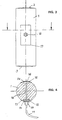
- the rod-like load cell 1 shown in FIGS. 1 and 2 has a circular cylindrical shape with spherical ends trained force application surfaces 2 and 3. However, you can also a polygonal, for example square, cross section exhibit. The adjacent end areas are set apart from the middle section by a smaller diameter.
- the load cell 1 has a bore 4 perpendicular to it Longitudinal axis.
- the end portions 5 of the bore 4 have something larger diameter, whereby circular end faces 6 formed for the support of disk-shaped covers 7, 8 are.
- the strain gauges 9 are inside the bore 4 arranged.
- the cover 8 is with a screw connection 10 provided for the implementation of a cable 11 through which Strain gauges 9 can be connected to an evaluation device.
- the covers 7, 8 are sealed in the bore by welding 4 attached.
- the load cell 1 To prevent the load cell 1 from rotating about its longitudinal axis is near the lower force introduction surface 3 with the Load cell 1 is provided in the form of an annular disk 12, which has an edge recess 13, in the assembled state the load cell 1 engages a stationary holder. Thereby is prevented that the load cell 1 can rotate and the Cable connection is damaged.
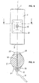
- the load cell is 1 continuously between the force introduction surfaces 2 and 3 circular cylindrical design. It shows two diametrically arranged recesses 14 on the bottom surfaces 15 strain gauges are attached.
- the recesses 14 are from Covers 16, 17 that arch the cylinder shape of the load cell 1 adapted and welded to their edges with this are.
- the cover 17 has a screw connection 10 for the Implementation of a cable 11.
- the recesses 14 are through a thin transverse bore 18 penetrating the load cell 1 with one another connected by an internal cable connection is led.
- the embodiment according to Figures 5 and 6 is special simply designed and therefore cheaper to manufacture.
- the between the force introduction surfaces 2 and 3 at the end continuous circular cylindrical load cell 1 requires mechanical Shaping only one transverse bore 18 because the areas 19 for the attachment of the strain gauges diametrically on the outer lateral surface of the load cell 1 are provided.
- the covers 20, 21 are hood-shaped and on its edges connected to the load cell 1 by welding.
- the cover 21 contains a screw connection 10 for the Implementation of a cable 11, which also via the transverse bore 18 connected to the strain gauges under the other cover is.
- load cells of FIGS. 3 can also be to 6 a safeguard against rotation about the longitudinal axis or a polygonal, e.g. square cross section can be provided.
- the load cells shown in Figures 1 to 6 are for determines the introduction of compressive forces.
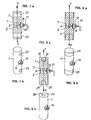
- An advantageous one Application of the invention to load cells for introducing tensile forces show the embodiments shown in Figures 7 to 9.
- the load cells 1 from a circular cylindrical rod, which is analog 1 to the cylinder axis to the load cell according to FIG has vertical bore 4 in which the strain gauges 9 are arranged.
- the bore 4 is with covers 7, 8 closed, the cover 8 a screw terminal 10 for carrying a cable 11.
- the force introduction surfaces are formed by transverse bores 22, 23 in the End sections of the load cells 1 parallel to each other and parallel are arranged to bore 8; however, they can too be perpendicular to the hole.
- the transverse bores 22, 23 are used to receive pins that the tensile forces F on the Transfer load cell 1.
- FIG. 8 shows an embodiment of the load cell 1 that for the introduction of force in the end faces 24, 25 coaxially Cylinder axis has threaded bores 26, 27 into which force is introduced suitable connecting elements, for example rods or Rod ends can be screwed in.
- 9a, 9b are for connection of force introduction components, the end sections of the load cell 1 each provided with an external thread 28, 29 on which the respective force introduction component can be screwed on.
- All embodiments according to the invention are very robust, in easy to manufacture and good against external interference secured.
- the metallic covers can be used in all Design cases and connect them to the load cell so that on the one hand good protection of the sensitive strain gauge assemblies is achieved and on the other hand that of the covers influences on the spring characteristic of the load cell to be neglected or simply to measure are compensating. Finally, attach the covers also connection methods applicable, which are not interfere with the measuring accuracy.
- the cable outlet of the Load cell is extremely simple using a commercially available tight cable gland accomplished that directly sits on the cover and in conjunction with the usual Potting compounds represent an effective seal. Internal Interconnections avoid the complex on the housing Load cell attached cable boxes.
- the invention Load cells can be manufactured very cheaply and everywhere applicable where weighing equipment with the lowest possible cost must be created.
Abstract
Description
Die Erfindung betrifft eine stabförmige Wägezelle gemäß dem
Oberbegriff des Patentanspruchs 1.The invention relates to a rod-shaped load cell according to the
Preamble of
Eine derartige Wägezelle ist aus der EP 0 315 846 B1 bekannt. Dabei handelt es sich um einen hantelförmig ausgebildeten Stab mit einem schlanken Zentrumsteil und wesentlich dickeren Endbereichen, wobei die Dehnungsmeßstreifen einschließlich Sensoren zur Linearisierung der Meßwerte und zur Temperaturkompensation etwa in der Mitte des Zentrumsteils angeordnet sind. Die bekannte Wägezelle ist selbstaufrichtend, d.h. die endseitigen Krafteinleitungsflächen sind so ausgeführt, daß zwangsläufig ein Rückstellmoment erzeugt wird, wenn die Wägezelle aus einer senkrechten Lage ausgelenkt wird. Der gesamte Zentrumsteil wird von einem Wellrohr überdeckt, das endseitig mit den dickeren Endbereichen der Wägezelle verbunden ist. Außerdem ist in einem Endbereich eine Querbohrung vorgesehen, die über dünnere Bohrungen mit der Oberfläche des Zentrumsteils verbunden ist und zur Aufnahme der von den Sensoren abgehenden Kabel bestimmt ist. Um die Beanspruchungen in der Wägezelle symmetrisch zu halten, ist es darüberhinaus erforderlich, weitere, für Verkabelungen nicht erforderliche Bohrungen im anderen Endbereich vorzusehen.Such a load cell is known from EP 0 315 846 B1. It is a dumbbell-shaped rod with a slim center part and much thicker end areas, the strain gauges including sensors for linearization of the measured values and for temperature compensation are arranged approximately in the middle of the center part. The known load cell is self-righting, i.e. the end Force application surfaces are designed so that inevitably a restoring moment is generated when the load cell is deflected from a vertical position. The entire center part is covered by a corrugated tube that ends with is connected to the thicker end areas of the load cell. Moreover a transverse bore is provided in an end region, the through thinner holes with the surface of the center part is connected and for receiving the outgoing from the sensors Cable is determined. To the stresses in the load cell keeping symmetrical, it is also necessary to Holes not required for wiring in the other Provide end area.
Diese bekannte Wägezelle ist in der Herstellung sehr aufwendig und teuer und daher in vielen Anwendungsfällen nicht wettbewerbsfähig, bei denen es vor allem auf einen robusten Aufbau und weniger auf höchste Meßempfindlichkeit und -genauigkeit ankommt. Insbesondere auch die Abdeckung mittels Wellrohr ist herstellungstechnisch kompliziert, weil sie nur realisierbar ist, wenn die zu verbindenden Bauteile maßlich genau aufeinander abgestimmt sind.This known load cell is very complex to manufacture and expensive and therefore not competitive in many applications, where it mainly relies on a sturdy construction and less on the highest measuring sensitivity and accuracy arrives. In particular, the cover is by means of a corrugated pipe technically complicated because they can only be realized is when the components to be connected are dimensionally accurate are coordinated.
Es sind weitere Bauformen von in der Funktion vergleichbaren selbstaufrichtenden Wägezellen bekannt, die ebenfalls aufwendige Gehäuse aufweisen. Bei der in der Firmendruckschrift "Wägezelle Reihe K, 7MH 3105, Betriebsanleitung" der Firma Siemens AG beschriebenen Wägezelle ist ein zweiteiliges Stahlblechgehäuse mit einer O-Ring Dichtung vorgesehen.There are other designs of comparable in function self-righting load cells known, which is also expensive Have housing. In the case of the "load cell Series K, 7MH 3105, operating instructions "from Siemens AG described load cell is a two-piece sheet steel housing provided with an O-ring seal.
Aus der EP 0 307 998 A2 ist ein Kraftaufnehmer bekannt, der über einen sich axial erstreckenden zylindrischen Stauchkörper verfügt, an dessen Enden abgerundete Kraftein- und Kraftausleitungsflächen angeordnet sind. Etwa axial in der Mitte des Stauchkörpers ist quer zur Axialrichtung eine groß dimensionierte Durchgangsbohrung vorgesehen, die durch zwei gegenüberliegend angeordnete scheibenförmige Trägerplatten abgedichtet ist. Dabei sind an der nach innen gerichteten ebenen Oberfläche jeder Trägerscheibe Dehnungsmeßstreifen in Schichttechnik aufgebracht. Die Trägerscheiben sind durch eine Schweiß- oder Lötverbindung parallel zueinander in den beiden gegenüberliegenden Bohrungsöffnungen befestigt und verschließen diese, so daß die Dehnungsmeßstreifen gegen Korrosion geschützt sind. Da die zu messende Kraft hauptsächlich über die Trägerplatten übertragen wird, hängt die Haltbarkeit und Dichtigkeit der Trägerplatten stark von der Güte der Schweiß- oder Lötverbindung ab, mit der die Trägerplatten mit dem Stauchkörper verbunden sind.A force transducer is known from EP 0 307 998 A2, which via an axially extending cylindrical compression body has rounded ends at the ends of the force input and force transmission are arranged. Approximately axially in the middle of the The upsetting body is a large one transverse to the axial direction Through hole provided by two opposite arranged disc-shaped carrier plates sealed is. Thereby are on the inward facing flat surface Strain gauges for each carrier disc using the layering technique applied. The carrier disks are welded or welded Solder connection parallel to each other in the two opposite Fixed holes and close them, see above that the strain gauges are protected against corrosion. There the force to be measured mainly via the carrier plates is transferred depends on the durability and tightness of the Carrier plates strongly depend on the quality of the welded or soldered connection from which the carrier plates are connected to the compression body are.
Aus der EP 0 107 966 B1 ist eine Lastmeßzelle bekannt, bei der die Dehnungsmeßstreifen mittels einer aufgeklebten Aluminiumverbundfolie abgedeckt sind. Derartige Abdeckungen haben zwar praktisch keinen Einfluß auf die Federkennlinie der Lastmeßzelle, sind aber nur feuchtigkeitsdicht, wenn die randseitigen Schnittkanten der Aluminium-Verbundfolie zusätzlich behandelt, beispielsweise mit einer aufgedampften Aluminiumnaht abgedeckt werden. Dadurch wird auch diese Art der Abdeckung ziemlich aufwendig, abgesehen davon, daß sie gegen mechanische Beschädigungen empfindlich ist und schon deswegen für viele Anwendungszwecke nicht in Betracht kommt. Außerdem bereitet die Herausführung der Kabel Schwierigkeiten.A load measuring cell is known from EP 0 107 966 B1, in which the strain gauges using a glued aluminum composite film are covered. Such covers have practically no influence on the spring characteristic of the load cell, but are only moisture-proof if the edges Cut edges of the aluminum composite film treated additionally, for example covered with a vapor-deposited aluminum seam become. This also makes this type of coverage pretty expensive, apart from the fact that it protects against mechanical damage is sensitive and therefore for many applications is out of the question. In addition, the Leading out the cables trouble.
Der Erfindung liegt die Aufgabe zugrunde, eine Wägezelle der eingangs genannten Art schaffen, die einfach aufgebaut und vergleichsweise billig herstellbar ist und die insbesondere eine sichere und technisch einfach zu realisierende Abdeckung der mit Dehnungsmeßstreifen bestückten Bereiche ermöglicht.The invention has for its object a load cell create the kind mentioned above, which are simply constructed and is comparatively cheap to manufacture and in particular a safe and technically easy to implement cover which enables areas equipped with strain gauges.
Diese Aufgabe wird durch die im Patentanspruch 1 angegebene
Erfindung gelöst. Weiterbildungen und vorteilhafte Ausführungsbeispiele
der Erfindung sind in den abhängigen Ansprüchen angegeben.This object is achieved by the specified in
Anders als die bekannte Aluminium-Verbundfolie kann eine solche metallische Abdeckung an jede Art von mechanischer Beanspruchung angepaßt werden, so daß für den jeweiligen Einsatzzweck eine ausreichend robuste Sicherung der Dehnungsmeßstreifen erreicht werden kann. Derartige metallische Abdeckungen lassen sich einfach herstellen und leicht an die jeweilige Geometrie der Wägezelle bzw. der Dehnungsmeßstreifenanordnung anpassen. Sie lassen sich außerdem leicht so gestalten, daß sie nur einen geringen Einfluß auf die Federkennlinie der Wägezelle haben bzw. daß ihr Einfluß verhältnismäßig leicht kompensierbar ist. Die Form der Abdeckung und ihre Verbindung mit der Wägezelle kann jeweils so ausgewählt werden, daß nachteilige Rückwirkungen praktisch auszuschließen sind.Unlike the well-known aluminum composite film, it can metallic cover to any type of mechanical stress be adjusted so that for the respective application a sufficiently robust securing of the strain gauges can be achieved. Leave such metallic covers easy to manufacture and easy on the respective geometry adapt the load cell or the strain gauge arrangement. They can also be easily designed so that they only have one have little influence on the spring characteristic of the load cell or that their influence can be compensated for relatively easily. The shape of the cover and its connection to the load cell can be selected so that adverse repercussions are practically excluded.
Die Verbindung der Abdeckung mit der Wägezelle kann durch Schweißen, insbesondere Laserschweißen, durch Löten oder Kleben erfolgen. In allen Fällen wird ein feuchtigkeitsdichter Abschluß der Bereiche mit Dehnungsmeßstreifen erreicht, ohne daß die mechanischen Eigenschaften der Wägezelle nennenswert beeinflußt werden. Die stabförmige Wägezelle selbst kann zwischen den endseitigen Krafteinleitungsflächen als einfaches Drehteil mit im wesentlichen gleichbleibendem, vorzugsweise gleichförmigem Querschnitt hergestellt werden und so die Forderung nach geringerem Herstellungsaufwand erfüllen. Selbstverständlich kann jedoch auch ein vieleckiger, z.B. quadratischer Querschnitt der stabförmigen Wägezelle oder von Bereichen der stabförmigen Wägezelle vorgesehen werden.The cover can be connected to the load cell by Welding, especially laser welding, by soldering or gluing respectively. In all cases, a moisture-tight seal the areas with strain gauges reached without significantly affects the mechanical properties of the load cell become. The rod-shaped load cell itself can be between the end-face force application surfaces as a simple turned part with essentially the same, preferably uniform Cross section are produced and so the demand for meet lower manufacturing costs. Of course However, a polygonal, e.g. square cross section the rod-shaped load cell or areas of the rod-shaped Load cell can be provided.
Bei einer vorteilhaften Ausführungsform der Erfindung ist vorgesehen, daß die Wägezelle etwa in der Mitte zwischen den endseitigen Krafteinleitungsflächen senkrecht zu ihrer Längsachse eine Bohrung aufweist und daß die Dehnungsmeßstreifen auf der Bohrungswandung angebracht sind. Damit ist in der Wägezelle in einfacher Weise ein geschwächter Querschnittsbereich geschaffen, der für das Anbringen der Dehnungsmeßstreifen bestens geeignet ist. Außerdem gewinnt man einen Raum, in dem die Dehnungsmeßstreifen gegen äußere mechanische Zerstörung bereits weitgehend gesichert sind. Zum Verschließen der Bohrung eignen sich einfach geformte Bleche wie tiefgezogene oder gedrückte Bleche. In an advantageous embodiment of the invention, that the load cell is approximately in the middle between the ends Force application surfaces perpendicular to their longitudinal axis has a hole and that the strain gauges on the Bore wall are attached. So that is in the load cell in easily created a weakened cross-sectional area, the best for attaching the strain gauges suitable is. You also win a room in which the strain gauges against external mechanical destruction are largely secured. Suitable for closing the hole simply shaped sheets such as deep-drawn or pressed Sheets.
Die Bohrung kann auch ohne großen Aufwand mit endseitigen Abschnitten von größerem Durchmesser versehen werden, wobei die kreisringförmigen Stirnflächen zwischen größerem und kleinerem Durchmesser als Auflage für eine kreisscheibenförmige Abdeckung dienen und eine besonders gute und leicht zu realisierende Verbindung zwischen Wägezelle und Abdeckung ermöglichen. Die Formgebung kann durch einfache spangebende Bearbeitung erfolgen und trägt dazu bei, daß die Wägezelle preisgünstig hergestellt werden kann.The bore can also be easily done with end sections be provided of larger diameter, the circular end faces between larger and smaller Diameter as a support for a circular disk-shaped cover serve and a particularly good and easy to implement Allow connection between load cell and cover. The Shaping can be done by simple machining and contributes to the fact that the load cell is manufactured inexpensively can be.
Bei einer anderen Ausführungsform der Erfindung ist vorgesehen, daß die Wägezelle etwa in der Mitte zwischen den endseitigen Krafteinleitungsflächen diametral gegenüberliegende Ausnehmungen aufweist, auf deren Basisflächen die Dehnungsmeßstreifen angebracht sind und daß die Ausnehmungen von Abdeckungen verschlossen sind, die diese randseitig übergreifen und mit der Wägezelle randseitig verbunden sind. Durch die Bemessung der Ausnehmungen nach Größe und Tiefe kann jede gewünschte Querschnittschwächung der Wägezelle erreicht werden, wobei auch hier lediglich ein einfacher, preiswerter Fräs- und/oder Bohrvorgang zur Herstellung erforderlich ist. Als Abdeckung können ebene oder vorgeformte Blechabschnitte verwendet werden, die die Ausnehmung überdecken und randseitig wiederum sehr bequem mit der Wägezelle zu verbinden sind.In another embodiment of the invention, that the load cell is approximately in the middle between the ends Force introduction surfaces diametrically opposite recesses has, on the base surfaces of the strain gauges are attached and that the recesses are closed by covers are that overlap these and with the Load cell are connected on the edge. By dimensioning the Recesses by size and depth can be any desired cross-sectional weakening the load cell can be reached, also here just a simple, inexpensive milling and / or drilling process is required for manufacture. Can use as cover flat or preformed sheet metal sections can be used cover the recess and again very comfortably at the edge to be connected to the load cell.
Schließlich kann man den Erfindungsgedanken auch bei einer im Querschnitt nicht geschwächten Wägezelle anwenden, indem die Dehnungsmeßstreifen einfach auf die vorzugsweise zylindrische Mantelfläche aufgebracht und mit einer deckelartigen, randseitig mit der Wägezelle verbundenen Abdeckung abgeschlossen sind. Bei dieser Ausführung erfordert die Wägezelle praktisch keine mechanische Bearbeitung zur Schaffung von Bereichen auf denen die Dehnungsmeßstreifen angebracht werden können. Durch entsprechende Gestaltung der Abdeckungen kann dafür gesorgt werden, daß die Dehnungsmeßstreifen gesichert werden, ohne daß die Abdeckungen mit den Dehnungsmeßstreifen in Berührung kommen. Finally, the idea of the invention can also be found in a Apply the cross-section of the weakened load cell using the Strain gauges simply on the preferably cylindrical Shell surface applied and with a lid-like edge cover connected to the load cell are completed. With this version, the load cell requires practically none machining to create areas on those the strain gauges can be attached. By appropriate Design of the covers can be ensured that the strain gauges are secured without the Covers come into contact with the strain gauges.
Bei den beiden letztgenannten Ausführungsformen ist es zweckmäßig, eine Querbohrung - bei Bedarf auch mehrere - vorzusehen, wodurch eine innenliegende Kabelführung zum Anschluß der Dehnungsmeßstreifen möglich und nur noch ein Kabelabgang nach außen erforderlich ist. Zu diesem Zweck weist auch eine der Abdeckungen wie bei der Ausführungsform nach den Figuren 1 und 2 einen Schraubanschluß für die Durchführung von Kabeln auf. Derartige Schraubanschlüsse sind für die verschiedensten Anwendungszwecke aus dem Stand der Technik bekannt. Ein separater Kabelkasten ist bei diesen Ausgestaltungen nicht erforderlich.In the latter two embodiments, it is expedient to to provide one cross hole - several if necessary - whereby an internal cable routing for connecting the strain gauges possible and only one cable outlet after outside is required. For this purpose, one of the Covers as in the embodiment of Figures 1 and 2 a screw connection for the passage of cables. Such screw connections are for a wide variety of applications known from the prior art. A separate one Cable box is not required in these configurations.
Um die Wägezelle gegen Verdrehen um ihre Längsachse zu sichern, kann erfindungsgemäß die Wägezelle eine mit einer ortsfesten Halterung zusammenwirkende ringförmige Sicherungsscheibe aufweisen, die an der Wägezelle befestigt ist.To prevent the load cell from rotating around its longitudinal axis, According to the invention, the load cell can have a fixed one Have holder cooperating annular locking washer, which is attached to the load cell.
Der Erfindungsgedanke läßt sich selbstverständlich auch bei Wägezellen anwenden, bei denen zumindest eine der Krafteinleitungsflächen eben ausgebildet ist. Die Krafteinleitungsfläche kann dabei auch mit Einrichtungen z.B. in Form von Gewindeeinrichtungen versehen sein, über die eine Verbindung der Wägezelle mit Krafteinleitungsbauteilen beispielsweise zur Aufbringung einer Zugbelastung möglich ist.The idea of the invention can of course also be used Use load cells in which at least one of the force application surfaces is just trained. The force application area can also be used with facilities e.g. in the form of thread devices be provided via a connection of the load cell with force introduction components, for example for application a tensile load is possible.
Die Erfindung wird nachfolgend anhand von Ausführungsbeispielen näher erläutert, die in der Zeichnung dargestellt sind. Es zeigen
Figur 1- eine perspektivische Darstellung einer Wägezelle mit in einer Bohrung angeordneten Dehnungsmeßstreifen,
Figur 2- einen Längsschnitt durch die Wägezelle gemäß
Figur 1, Figur 3- eine Ansicht einer zylindrischen Wägezelle mit Ausnehmungen zur Aufnahme der Dehnungsmeßstreifen,
Figur 4- einen Querschnitt durch die Wägezelle gemäß
Figur 3, Figur 5- eine Ansicht einer zylindrischen Wägezelle mit auf der Mantelfläche angeordneten Dehnungsmeßstreifen,
- Figur 6
- einen Querschnitt durch die Wägezelle gemäß
Figur 5, - Figur 7a
- einen Längsschnitt durch eine Wägezelle mit Querbohrungen als Krafteinleitungsflächen,
- Figur 7b
- eine perspektivische Darstellung der Wägezelle gemäß Figur 7 a,
- Figur 8a
- einen Längsschnitt durch eine Wägezelle mit endseitigen Gewindebohrungen als Krafteinleitungsflächen,
- Figur 8b
- eine perspektivische Darstellung der Wägezelle gemäß Figur 8a,
- Figur 9a
- ein Längsschnitt durch eine Wägezelle mit endseitigen Außengewinden als Krafteinleitungsflächen und
- Figur 9b
- eine perspektivische Darstellung der Wägezelle gemäß Figur 9a.
- Figure 1
- 1 shows a perspective illustration of a load cell with strain gauges arranged in a bore,
- Figure 2
- 2 shows a longitudinal section through the load cell according to FIG. 1,
- Figure 3
- 1 shows a view of a cylindrical load cell with recesses for receiving the strain gauges,
- Figure 4
- 3 shows a cross section through the load cell according to FIG. 3,
- Figure 5
- 1 shows a view of a cylindrical load cell with strain gauges arranged on the lateral surface,
- Figure 6
- 3 shows a cross section through the load cell according to FIG. 5,
- Figure 7a
- a longitudinal section through a load cell with transverse bores as force introduction surfaces,
- Figure 7b
- 6 shows a perspective illustration of the load cell according to FIG. 7 a,
- Figure 8a
- a longitudinal section through a load cell with threaded bores at the ends as force introduction surfaces,
- Figure 8b
- 6 shows a perspective illustration of the load cell according to FIG. 8a,
- Figure 9a
- a longitudinal section through a load cell with external threads as force introduction surfaces and
- Figure 9b
- a perspective view of the load cell according to Figure 9a.
Die in den Figuren 1 und 2 dargestellte stabartige Wägezelle 1
hat eine kreiszylindrische Form mit endseitigen, sphärisch
ausgebildeten Krafteinleitungsflächen 2 und 3. Sie kann jedoch
auch einen vieleckigen, beispielsweise quadratischen Querschnitt
aufweisen. Die diesen benachbarten Endbereiche sind
durch einen kleineren Durchmesser vom Mittelteil etwas abgesetzt.
In der Mitte zwischen den beiden Krafteinleitungsflächen
2 und 3 besitzt die Wägezelle 1 eine Bohrung 4 senkrecht zur
Längsachse. Die Endabschnitte 5 der Bohrung 4 haben einen etwas
größeren Durchmesser, wodurch kreisringförmige Stirnflächen 6
für die Auflage scheibenförmiger Abdeckungen 7, 8 gebildet
sind. Innerhalb der Bohrung 4 sind die Dehnungsmeßstreifen 9
angeordnet. Die Abdeckung 8 ist mit einem Schraubanschluß 10
für die Durchführung eines Kabels 11 versehen, über das die
Dehnungsmeßstreifen 9 an ein Auswertegerät anschließbar sind.
Die Abdeckungen 7, 8 sind durch Schweißen dicht in der Bohrung
4 befestigt.The rod-
Zur Sicherung gegen Verdrehen der Wägezelle 1 um ihre Längsachse
ist nahe der unteren Krafteinleitungfläche 3 eine mit der
Wägezelle 1 fest verbundene ringförmige Scheibe 12 vorgesehen,
die eine Randausnehmung 13 hat, in die in montiertem Zustand
der Wägezelle 1 eine ortsfeste Halterung eingreift. Dadurch
wird verhindert, daß sich die Wägezelle 1 drehen kann und der
Kabelanschluß beschädigt wird.To prevent the
Bei der Ausführungsform gemäß den Figuren 3 und 4 ist die Wägezelle
1 zwischen den Krafteinleitungsflächen 2 und 3 durchgehend
kreiszylindrisch ausgebildet. Sie weist zwei diametral
angeordnete Ausnehmungen 14 auf, an deren Bodenflächen 15 Dehnungsmeßstreifen
angebracht sind. Die Ausnehmungen 14 sind von
Abdeckungen 16, 17 überwölbt, die der Zylinderform der Wägezelle
1 angepaßt und an ihren Rändern mit dieser verschweißt
sind. Die Abdeckung 17 hat einen Schraubanschluß 10 für die
Durchführung eines Kabels 11. Die Ausnehmungen 14 sind durch
eine dünne, die Wägezelle 1 durchdringende Querbohrung 18 miteinander
verbunden, durch die eine innenliegende Kabelverbindung
geführt ist.In the embodiment according to FIGS. 3 and 4, the load cell is
1 continuously between the force introduction surfaces 2 and 3
circular cylindrical design. It shows two diametrically
arranged recesses 14 on the bottom surfaces 15 strain gauges
are attached. The
Die Ausführungsform gemäß den Figuren 5 und 6 ist besonders
einfach gestaltet und in der Herstellung daher noch günstiger.
Die zwischen den endseitigen Krafteinleitungsflächen 2 und 3
durchgehend kreiszylindrische Wägezelle 1 erfordert an mechanischer
Formgebung nur eine Querbohrung 18, weil die Bereiche 19
für die Anbringung der Dehnungsmeßstreifen diametral auf der
äußeren Mantelfläche der Wägezelle 1 vorgesehen sind. In diesem
Fall sind die Abdeckungen 20, 21 haubenartig ausgebildet und an
ihren Rändern durch Schweißen mit der Wägezelle 1 verbunden.
Die Abdeckung 21 enthält einen Schraubanschluß 10 für die
Durchführung eines Kabels 11, das über die Querbohrung 18 auch
mit den Dehnungsmeßstreifen unter der anderen Abdeckung verbunden
ist.The embodiment according to Figures 5 and 6 is special
simply designed and therefore cheaper to manufacture.
The between the force introduction surfaces 2 and 3 at the end
continuous circular
Selbstverständlich kann auch bei den Wägezellen der Figuren 3 bis 6 eine Sicherung gegen Verdrehen um die Längsachse oder ein vieleckiger, z.B. quadratischer Querschnitt vorgesehen werden. Of course, the load cells of FIGS. 3 can also be to 6 a safeguard against rotation about the longitudinal axis or a polygonal, e.g. square cross section can be provided.
Die in den Figuren 1 bis 6 dargestellten Wägezellen sind für
die Einleitung von Druckkräften bestimmt. Eine vorteilhafte
Anwendung der Erfindung bei Wägezellen zur Einleitung von Zugkräften
zeigen die in den Figuren 7 bis 9 dargestellten Ausführungsbeispiele.
Bei diesen Ausführungsbeispielen bestehen
die Wägezellen 1 aus einem kreiszylindrischen Stab, der analog
zu der Wägezelle gemäß Figur 1 in seiner Mitte eine zur Zylinderachse
senkrechte Bohrung 4 hat, in der die Dehnungsmeßstreifen
9 angeordnet sind. Die Bohrung 4 ist mit Abdeckungen 7, 8
verschlossen, wobei die Abdeckung 8 einen Schraubanschluß 10
zur Durchführung eines Kabels 11 aufweist.The load cells shown in Figures 1 to 6 are for
determines the introduction of compressive forces. An advantageous one
Application of the invention to load cells for introducing tensile forces
show the embodiments shown in Figures 7 to 9.
In these embodiments exist
the
Bei der Wägezelle gemäß den Figuren 7a, 7b werden die Krafteinleitungsflächen
durch Querbohrungen 22, 23 gebildet, die in den
Endabschnitten der Wägezellen 1 parallel zueinander und parallel
zur Bohrung 8 angeordnet sind; sie können jedoch auch
senkrecht zur Bohrung angeordnet sein. Die Querbohrungen 22, 23
dienen zur Aufnahme von Zapfen, die die Zugkräfte F auf die
Wägezelle 1 übertragen.In the load cell according to FIGS. 7a, 7b, the force introduction surfaces are
formed by
In Figur 8 ist eine Ausgestaltung der Wägezelle 1 gezeigt, die
zur Krafteinleitung in den Stirnflächen 24, 25 koaxial zur
Zylinderachse Gewindebohrungen 26, 27 hat, in die zur Krafteinleitung
geeignete Anschlußglieder, beispielsweise Stangen oder
Gelenkköpfe einschraubbar sind.FIG. 8 shows an embodiment of the
Bei der Wägezelle gemäß den Figuren 9a, 9b sind zum Anschluß
von Krafteinleitungsbauteilen die Endabschnitte der Wägezelle 1
jeweils mit einem Außengewinde 28, 29 versehen, auf das das
jeweilige Krafteinleitungsbauteil aufschraubbar ist.9a, 9b are for connection
of force introduction components, the end sections of the
Alle erfindungsgemäßen Ausführungsformen sind sehr robust, in der Herstellung einfach und gegen äußere Störeinflüsse gut gesichert. Die metallischen Abdeckungen lassen sich in allen Fällen so gestalten und mit der Wägezelle verbinden, daß einerseits ein guter Schutz der empfindlichen Dehnungsmeßstreifenanordnungen erreicht wird und andererseits die von den Abdekkungen ausgehenden Einflüsse auf die Federkennlinie der Wägezelle zu vernachlässigen oder aber meßtechnisch einfach zu kompensieren sind. Schließlich sind zur Befestigung der Abdekkungen auch Verbindungsmethoden anwendbar, die sich nicht störend auf die Meßgenauigkeit auswirken. Der Kabelabgang der Wägezelle wird in äußerst einfacher Weise über eine handelsübliche dichte Kabelverschraubung bewerkstelligt, die direkt auf der Abdeckung sitzt und in Verbindung mit den üblichen Vergußmassen eine wirkungsvolle Abdichtung darstellt. Interne Verschaltungen vermeiden die aufwendigen auf das Gehäuse einer Wägezelle aufgebrachten Kabelkästen. Die erfindungsgemäßen Wägezellen sind sehr preisgünstig herstellbar und überall dort anwendbar, wo Wägeeinrichtungen mit möglichst niedrigem Kostenaufwand erstellt werden müssen.All embodiments according to the invention are very robust, in easy to manufacture and good against external interference secured. The metallic covers can be used in all Design cases and connect them to the load cell so that on the one hand good protection of the sensitive strain gauge assemblies is achieved and on the other hand that of the covers influences on the spring characteristic of the load cell to be neglected or simply to measure are compensating. Finally, attach the covers also connection methods applicable, which are not interfere with the measuring accuracy. The cable outlet of the Load cell is extremely simple using a commercially available tight cable gland accomplished that directly sits on the cover and in conjunction with the usual Potting compounds represent an effective seal. internal Interconnections avoid the complex on the housing Load cell attached cable boxes. The invention Load cells can be manufactured very cheaply and everywhere applicable where weighing equipment with the lowest possible cost must be created.
Claims (15)
- Rod-shaped load cell (1) or force transducer for substantially axially applied loads having preferably spherically designed force introduction end faces (2, 3), as well as having at least one region for mounting strain gauges (9), which is disposed between the force introduction end faces (2, 3) and lies under a metal cover (7, 8; 16, 17; 20, 21), which extends only over a minor part of the periphery of the load cell (1) and which at the edge is connected sealingly to the load cell (1), characterized in that the strain gauges (9) are mounted directly on the rod-shaped load cell body (1) and that the cover (7, 8; 16, 17; 20, 21) are at a radial distance from the strain gauges (9).
- Load cell according to claim 1, characterized in that the cover (7, 8; 16, 17; 20, 21) is connected by welding, in particular laser welding, to the load cell (1).
- Load cell according to claim 1, characterized in that the cover (7, 8; 16, 17; 20, 21) is connected by soldering to the load cell (1).
- Load cell according to claim 1, characterized in that the cover (7, 8; 16, 17; 20, 21) is connected by gluing to the load cell (1).
- Load cell according to one of claims 1 to 4, characterized in that the rod-shaped load cell (1) between the force introduction end faces (2, 3) has a substantially constant cross section.
- Load cell according to claim 5, characterized in that the load cell (1) has a circular or polygonal cross section.
- Load cell according to one of claims 1, 5 or 6, characterized in that the load cell (1) approximately in the middle between the force introduction end faces (2, 3) and at right angles to its longitudinal axis has a bore (4) and that the strain gauges (5) are mounted on the bore wall.
- Load cell according to claim 7, characterized in that the bore (4) has end portions (5) of larger diameter, that disk-shaped or cup-shaped metal covers (7, 8) are disposed in the end portions (5) and are supported against the annular end faces (6) between the larger and the smaller diameter of the bore (4) and are connected at their edge to the load cell (1).
- Load cell according to claim 1, 5 or 6, characterized in that the load cell (1) approximately in the middle between the force introduction end faces (2, 3) has diametrically disposed recesses (14), on the base surfaces (15) of which the strain gauges are mounted, and that the recesses (14) are closed by covers (16, 17), which overlap said recesses and are connected at their edge to the load cell (1).
- Load cell according to claim 1, 5 or 6, characterized in that the strain gauges (5) are mounted approximately in the middle between the force introduction end faces (1, 2) diametrically on the lateral surface of the load cell (1) and that the regions (19) provided with strain gauges are closed off by means of a lid-like cover (20, 21), which is connected at the edges to the load cell (1).
- Load cell according to claim 9 or 10, characterized in that the recesses (14) and/or the regions (19) having strain gauges are connected to one another by a narrow transverse bore (18) for the passing through of cables.
- Load cell according to one of claims 1 to 11, characterized in that one cover (8, 17, 21) has a screw-type connection (10) for the passing through of a cable (11).
- Load cell according to one of claims 1 to 12, characterized in that the load cell (1) has a device, which locks the load cell against rotation about its longitudinal axis and cooperates with a stationary holding device.
- Load cell according to one of claims 1 to 13, characterized in that at least one of the force introduction faces is flat.
- Load cell according to claim 14, characterized in that the force introduction face is provided with devices, preferably threaded devices, for connection to force introduction components.
Applications Claiming Priority (2)
| Application Number | Priority Date | Filing Date | Title |
|---|---|---|---|
| DE29510678U | 1995-07-07 | ||
| DE29510678U DE29510678U1 (en) | 1995-07-07 | 1995-07-07 | Load cell |
Publications (3)
| Publication Number | Publication Date |
|---|---|
| EP0752575A2 EP0752575A2 (en) | 1997-01-08 |
| EP0752575A3 EP0752575A3 (en) | 1998-03-04 |
| EP0752575B1 true EP0752575B1 (en) | 2002-08-07 |
Family
ID=8010007
Family Applications (1)
| Application Number | Title | Priority Date | Filing Date |
|---|---|---|---|
| EP96107329A Expired - Lifetime EP0752575B1 (en) | 1995-07-07 | 1996-05-09 | Load cell |
Country Status (5)
| Country | Link |
|---|---|
| US (1) | US5712432A (en) |
| EP (1) | EP0752575B1 (en) |
| AT (1) | ATE221987T1 (en) |
| DE (3) | DE29510678U1 (en) |
| ES (1) | ES2178689T3 (en) |
Cited By (1)
| Publication number | Priority date | Publication date | Assignee | Title |
|---|---|---|---|---|
| DE102004047508B3 (en) * | 2004-09-28 | 2006-04-20 | Hottinger Baldwin Messtechnik Gmbh | Transducers |
Families Citing this family (3)
| Publication number | Priority date | Publication date | Assignee | Title |
|---|---|---|---|---|
| DE102006025509A1 (en) * | 2006-05-30 | 2006-12-14 | Gtm Gassmann Testing And Metrology Gmbh | Pressure detector having expandable measuring strips on a deformable hollow cylindrical body |
| WO2019032470A1 (en) * | 2017-08-05 | 2019-02-14 | Interface, Inc. | Axial force pressure transducer |
| DE102020109799A1 (en) | 2020-04-08 | 2021-10-14 | IMES Intelligent Measuring Systems GmbH | Load cell |
Family Cites Families (19)
| Publication number | Priority date | Publication date | Assignee | Title |
|---|---|---|---|---|
| GB626206A (en) * | 1944-12-02 | 1949-07-12 | British Iron Steel Research | Improvements in or relating to stress indicators |
| US2488347A (en) * | 1945-09-12 | 1949-11-15 | Cox & Stevens Aireraft Corp | Electrical compression measuring device |
| US3037178A (en) * | 1959-08-10 | 1962-05-29 | Baldwin Lima Hamilton Corp | Load cell |
| US3100290A (en) * | 1961-01-04 | 1963-08-06 | Revere Corp America | Columnar stress sensing member |
| US3365689A (en) * | 1966-04-26 | 1968-01-23 | Kutsay Ali Umit | Strain gage apparatus |
| US3911737A (en) * | 1974-06-27 | 1975-10-14 | Ormond Alfred N | Heavy duty load cell |
| DE8030920U1 (en) * | 1980-11-19 | 1982-10-14 | Philips Patentverwaltung Gmbh, 2000 Hamburg | Force transducer |
| DD218677A1 (en) * | 1981-12-23 | 1985-02-13 | Robotron Messelekt | ELECTRIC POWER ENGINE |
| DE3236532A1 (en) * | 1982-10-02 | 1984-04-05 | Philips Patentverwaltung Gmbh, 2000 Hamburg | Force transducer |
| AU547838B2 (en) * | 1982-10-26 | 1985-11-07 | Ishida Koki Seisakusho K.K. | Load cell |
| DE3405127A1 (en) * | 1984-02-14 | 1985-09-05 | Philips Patentverwaltung Gmbh, 2000 Hamburg | Force transducer |
| DE3427573A1 (en) * | 1984-07-26 | 1986-02-06 | Philips Patentverwaltung Gmbh, 2000 Hamburg | Force transducer |
| US4733571A (en) * | 1986-10-24 | 1988-03-29 | Ormond Alfred N | Linearization of column-type load cell |
| DE3730703A1 (en) * | 1987-09-12 | 1989-03-23 | Philips Patentverwaltung | Force transducer |
| DE3730702A1 (en) * | 1987-09-12 | 1989-03-23 | Philips Patentverwaltung | Force transducer |
| US4804053B1 (en) * | 1987-11-10 | 1996-09-03 | Flintab Ab | Rocker pin load cell |
| US5076375A (en) * | 1987-11-30 | 1991-12-31 | Mettler-Toledo, Inc. | Load cell |
| US4789035A (en) * | 1988-03-28 | 1988-12-06 | Eaton Corporation | Load cell |
| DE4009286C2 (en) * | 1990-03-22 | 2000-11-23 | Wiegand Gmbh & Co Alexander | Arrangement for measuring the torsion of a rod-shaped hollow body |
-
1995
- 1995-07-07 DE DE29510678U patent/DE29510678U1/en not_active Expired - Lifetime
- 1995-10-06 DE DE1995137288 patent/DE19537288A1/en not_active Withdrawn
- 1995-12-13 US US08/571,540 patent/US5712432A/en not_active Expired - Lifetime
-
1996
- 1996-05-09 EP EP96107329A patent/EP0752575B1/en not_active Expired - Lifetime
- 1996-05-09 DE DE59609527T patent/DE59609527D1/en not_active Expired - Lifetime
- 1996-05-09 ES ES96107329T patent/ES2178689T3/en not_active Expired - Lifetime
- 1996-05-09 AT AT96107329T patent/ATE221987T1/en not_active IP Right Cessation
Cited By (1)
| Publication number | Priority date | Publication date | Assignee | Title |
|---|---|---|---|---|
| DE102004047508B3 (en) * | 2004-09-28 | 2006-04-20 | Hottinger Baldwin Messtechnik Gmbh | Transducers |
Also Published As
| Publication number | Publication date |
|---|---|
| DE19537288A1 (en) | 1997-01-09 |
| ES2178689T3 (en) | 2003-01-01 |
| DE29510678U1 (en) | 1995-08-17 |
| US5712432A (en) | 1998-01-27 |
| EP0752575A3 (en) | 1998-03-04 |
| EP0752575A2 (en) | 1997-01-08 |
| ATE221987T1 (en) | 2002-08-15 |
| DE59609527D1 (en) | 2002-09-12 |
Similar Documents
| Publication | Publication Date | Title |
|---|---|---|
| EP3507580B1 (en) | Torque sensor with a radially elastic torque transfer | |
| EP0351006B1 (en) | Pressure or force transducer using an axial-symmetric circular spring | |
| EP3507582B1 (en) | Torque sensor with seal membrane | |
| WO1994021992A1 (en) | Pressure difference measurement converter | |
| EP0542956A1 (en) | Device for securing in an electrically insulated manner a metallic probe electrode in the opening of a housing. | |
| EP0052257A2 (en) | Electromechanical flexure force sensor, especially for weighing devices | |
| EP0745829B1 (en) | Measuring cable-transducer having a shell housing | |
| EP0090872A1 (en) | High pressure detector | |
| DE2744864B2 (en) | Device for fastening a probe in an opening of a container | |
| CH682108A5 (en) | ||
| DE4234290A1 (en) | Crystalline membrane pressure sensor assemmbly has flush sealed face - uses tapered sensor fixing hole to compress gasket suited for food and medical processing | |
| EP0342253B1 (en) | Mounting of a force transducer in a measuring platform | |
| EP0752575B1 (en) | Load cell | |
| DE10360941A1 (en) | Tubular pressure sensor | |
| DE3833364A1 (en) | VIBRATION DETECTING DEVICE | |
| DE4444922C1 (en) | Sensor fixing arrangement for measuring or counting sensor fixed in wall opening | |
| EP1922533A1 (en) | Modular construction measurement axle | |
| DE10145566A1 (en) | Device for measuring the flow rate and / or the flow of a fluid | |
| DE3922331A1 (en) | GAS DETECTOR | |
| DE2818140A1 (en) | FORCE MEASURING CELL, IN PARTICULAR WEIGHT CELL WITH A MEASURING BODY THAT CAN BE STRESSED ON BENDING | |
| EP0179278A2 (en) | Pressure sensor | |
| EP3818601B1 (en) | Explosion-proof housing with pressure relief | |
| DE3608393C2 (en) | ||
| EP0875972B1 (en) | Device for optical detection of arcing in switchgear | |
| DE19516326C2 (en) | Device for measuring differential pressure |
Legal Events
| Date | Code | Title | Description |
|---|---|---|---|
| PUAI | Public reference made under article 153(3) epc to a published international application that has entered the european phase |
Free format text: ORIGINAL CODE: 0009012 |
|
| AK | Designated contracting states |
Kind code of ref document: A2 Designated state(s): AT BE CH DE ES FR GB IT LI NL SE |
|
| PUAL | Search report despatched |
Free format text: ORIGINAL CODE: 0009013 |
|
| AK | Designated contracting states |
Kind code of ref document: A3 Designated state(s): AT BE CH DE ES FR GB IT LI NL SE |
|
| 17P | Request for examination filed |
Effective date: 19980821 |
|
| 17Q | First examination report despatched |
Effective date: 20001116 |
|
| GRAG | Despatch of communication of intention to grant |
Free format text: ORIGINAL CODE: EPIDOS AGRA |
|
| GRAG | Despatch of communication of intention to grant |
Free format text: ORIGINAL CODE: EPIDOS AGRA |
|
| GRAH | Despatch of communication of intention to grant a patent |
Free format text: ORIGINAL CODE: EPIDOS IGRA |
|
| GRAH | Despatch of communication of intention to grant a patent |
Free format text: ORIGINAL CODE: EPIDOS IGRA |
|
| GRAA | (expected) grant |
Free format text: ORIGINAL CODE: 0009210 |
|
| AK | Designated contracting states |
Kind code of ref document: B1 Designated state(s): AT BE CH DE ES FR GB IT LI NL SE |
|
| PG25 | Lapsed in a contracting state [announced via postgrant information from national office to epo] |
Ref country code: NL Free format text: LAPSE BECAUSE OF FAILURE TO SUBMIT A TRANSLATION OF THE DESCRIPTION OR TO PAY THE FEE WITHIN THE PRESCRIBED TIME-LIMIT Effective date: 20020807 |
|
| REF | Corresponds to: |
Ref document number: 221987 Country of ref document: AT Date of ref document: 20020815 Kind code of ref document: T |
|
| REG | Reference to a national code |
Ref country code: GB Ref legal event code: FG4D Free format text: NOT ENGLISH |
|
| REG | Reference to a national code |
Ref country code: CH Ref legal event code: EP |
|
| GBT | Gb: translation of ep patent filed (gb section 77(6)(a)/1977) |
Effective date: 20020807 |
|
| REF | Corresponds to: |
Ref document number: 59609527 Country of ref document: DE Date of ref document: 20020912 |
|
| PG25 | Lapsed in a contracting state [announced via postgrant information from national office to epo] |
Ref country code: SE Free format text: LAPSE BECAUSE OF FAILURE TO SUBMIT A TRANSLATION OF THE DESCRIPTION OR TO PAY THE FEE WITHIN THE PRESCRIBED TIME-LIMIT Effective date: 20021107 |
|
| ET | Fr: translation filed | ||
| REG | Reference to a national code |
Ref country code: ES Ref legal event code: FG2A Ref document number: 2178689 Country of ref document: ES Kind code of ref document: T3 |
|
| NLV1 | Nl: lapsed or annulled due to failure to fulfill the requirements of art. 29p and 29m of the patents act | ||
| PLBI | Opposition filed |
Free format text: ORIGINAL CODE: 0009260 |
|
| PLBQ | Unpublished change to opponent data |
Free format text: ORIGINAL CODE: EPIDOS OPPO |
|
| PG25 | Lapsed in a contracting state [announced via postgrant information from national office to epo] |
Ref country code: LI Free format text: LAPSE BECAUSE OF NON-PAYMENT OF DUE FEES Effective date: 20030531 Ref country code: CH Free format text: LAPSE BECAUSE OF NON-PAYMENT OF DUE FEES Effective date: 20030531 Ref country code: BE Free format text: LAPSE BECAUSE OF NON-PAYMENT OF DUE FEES Effective date: 20030531 |
|
| PLBF | Reply of patent proprietor to notice(s) of opposition |
Free format text: ORIGINAL CODE: EPIDOS OBSO |
|
| 26 | Opposition filed |
Opponent name: GWT GLOBAL WEIGHING TECHNOLOGIES GMBH Effective date: 20030505 |
|
| PLAX | Notice of opposition and request to file observation + time limit sent |
Free format text: ORIGINAL CODE: EPIDOSNOBS2 |
|
| BERE | Be: lapsed |
Owner name: *HOTTINGER BALDWIN MESSTECHNIK G.M.B.H. Effective date: 20030531 |
|
| REG | Reference to a national code |
Ref country code: CH Ref legal event code: PL |
|
| PLBB | Reply of patent proprietor to notice(s) of opposition received |
Free format text: ORIGINAL CODE: EPIDOSNOBS3 |
|
| PLCK | Communication despatched that opposition was rejected |
Free format text: ORIGINAL CODE: EPIDOSNREJ1 |
|
| APBP | Date of receipt of notice of appeal recorded |
Free format text: ORIGINAL CODE: EPIDOSNNOA2O |
|
| APBQ | Date of receipt of statement of grounds of appeal recorded |
Free format text: ORIGINAL CODE: EPIDOSNNOA3O |
|
| APAA | Appeal reference recorded |
Free format text: ORIGINAL CODE: EPIDOS REFN |
|
| APAH | Appeal reference modified |
Free format text: ORIGINAL CODE: EPIDOSCREFNO |
|
| APBU | Appeal procedure closed |
Free format text: ORIGINAL CODE: EPIDOSNNOA9O |
|
| PLBN | Opposition rejected |
Free format text: ORIGINAL CODE: 0009273 |
|
| STAA | Information on the status of an ep patent application or granted ep patent |
Free format text: STATUS: OPPOSITION REJECTED |
|
| 27O | Opposition rejected |
Effective date: 20051219 |
|
| PGFP | Annual fee paid to national office [announced via postgrant information from national office to epo] |
Ref country code: AT Payment date: 20070510 Year of fee payment: 12 |
|
| PGFP | Annual fee paid to national office [announced via postgrant information from national office to epo] |
Ref country code: GB Payment date: 20070517 Year of fee payment: 12 |
|
| GBPC | Gb: european patent ceased through non-payment of renewal fee |
Effective date: 20080509 |
|
| PG25 | Lapsed in a contracting state [announced via postgrant information from national office to epo] |
Ref country code: AT Free format text: LAPSE BECAUSE OF NON-PAYMENT OF DUE FEES Effective date: 20080509 |
|
| PG25 | Lapsed in a contracting state [announced via postgrant information from national office to epo] |
Ref country code: GB Free format text: LAPSE BECAUSE OF NON-PAYMENT OF DUE FEES Effective date: 20080509 |
|
| REG | Reference to a national code |
Ref country code: DE Ref legal event code: R082 Ref document number: 59609527 Country of ref document: DE Representative=s name: SCHWEIZER, JOACHIM, DIPL.-ING., DE |
|
| REG | Reference to a national code |
Ref country code: FR Ref legal event code: PLFP Year of fee payment: 20 |
|
| PGFP | Annual fee paid to national office [announced via postgrant information from national office to epo] |
Ref country code: DE Payment date: 20150601 Year of fee payment: 20 Ref country code: ES Payment date: 20150520 Year of fee payment: 20 |
|
| PGFP | Annual fee paid to national office [announced via postgrant information from national office to epo] |
Ref country code: IT Payment date: 20150528 Year of fee payment: 20 Ref country code: FR Payment date: 20150519 Year of fee payment: 20 |
|
| REG | Reference to a national code |
Ref country code: DE Ref legal event code: R071 Ref document number: 59609527 Country of ref document: DE |
|
| REG | Reference to a national code |
Ref country code: ES Ref legal event code: FD2A Effective date: 20160826 |
|
| PG25 | Lapsed in a contracting state [announced via postgrant information from national office to epo] |
Ref country code: ES Free format text: LAPSE BECAUSE OF EXPIRATION OF PROTECTION Effective date: 20160510 |