EP0751795B1 - Verfahren und vorrichtung zum befüllem von pulverbehältern - Google Patents
Verfahren und vorrichtung zum befüllem von pulverbehältern Download PDFInfo
- Publication number
- EP0751795B1 EP0751795B1 EP95918690A EP95918690A EP0751795B1 EP 0751795 B1 EP0751795 B1 EP 0751795B1 EP 95918690 A EP95918690 A EP 95918690A EP 95918690 A EP95918690 A EP 95918690A EP 0751795 B1 EP0751795 B1 EP 0751795B1
- Authority
- EP
- European Patent Office
- Prior art keywords
- particulate material
- plate
- apertures
- container
- hopper
- Prior art date
- Legal status (The legal status is an assumption and is not a legal conclusion. Google has not performed a legal analysis and makes no representation as to the accuracy of the status listed.)
- Expired - Lifetime
Links
Images


Classifications
-
- A—HUMAN NECESSITIES
- A61—MEDICAL OR VETERINARY SCIENCE; HYGIENE
- A61M—DEVICES FOR INTRODUCING MEDIA INTO, OR ONTO, THE BODY; DEVICES FOR TRANSDUCING BODY MEDIA OR FOR TAKING MEDIA FROM THE BODY; DEVICES FOR PRODUCING OR ENDING SLEEP OR STUPOR
- A61M15/00—Inhalators
- A61M15/0028—Inhalators using prepacked dosages, one for each application, e.g. capsules to be perforated or broken-up
- A61M15/0045—Inhalators using prepacked dosages, one for each application, e.g. capsules to be perforated or broken-up using multiple prepacked dosages on a same carrier, e.g. blisters
-
- A—HUMAN NECESSITIES
- A61—MEDICAL OR VETERINARY SCIENCE; HYGIENE
- A61M—DEVICES FOR INTRODUCING MEDIA INTO, OR ONTO, THE BODY; DEVICES FOR TRANSDUCING BODY MEDIA OR FOR TAKING MEDIA FROM THE BODY; DEVICES FOR PRODUCING OR ENDING SLEEP OR STUPOR
- A61M15/00—Inhalators
- A61M15/0028—Inhalators using prepacked dosages, one for each application, e.g. capsules to be perforated or broken-up
- A61M15/003—Inhalators using prepacked dosages, one for each application, e.g. capsules to be perforated or broken-up using capsules, e.g. to be perforated or broken-up
- A61M15/0033—Details of the piercing or cutting means
-
- B—PERFORMING OPERATIONS; TRANSPORTING
- B65—CONVEYING; PACKING; STORING; HANDLING THIN OR FILAMENTARY MATERIAL
- B65B—MACHINES, APPARATUS OR DEVICES FOR, OR METHODS OF, PACKAGING ARTICLES OR MATERIALS; UNPACKING
- B65B1/00—Packaging fluent solid material, e.g. powders, granular or loose fibrous material, loose masses of small articles, in individual containers or receptacles, e.g. bags, sacks, boxes, cartons, cans, or jars
- B65B1/04—Methods of, or means for, filling the material into the containers or receptacles
- B65B1/16—Methods of, or means for, filling the material into the containers or receptacles by pneumatic means, e.g. by suction
-
- A—HUMAN NECESSITIES
- A61—MEDICAL OR VETERINARY SCIENCE; HYGIENE
- A61M—DEVICES FOR INTRODUCING MEDIA INTO, OR ONTO, THE BODY; DEVICES FOR TRANSDUCING BODY MEDIA OR FOR TAKING MEDIA FROM THE BODY; DEVICES FOR PRODUCING OR ENDING SLEEP OR STUPOR
- A61M2202/00—Special media to be introduced, removed or treated
- A61M2202/06—Solids
- A61M2202/064—Powder
Definitions
- the invention relates to a method of loading a container and a plurality of individual doses of particulate material, particularly powdered medicament, contained therein, and to apparatus for performing the method.
- the invention is of particular application to devices for administering single doses of powdered medicament by inhalation.
- Such compounds can be provided in containers, each of which has a number of compartments, each containing a respective dose of the compound. Such containers are used in conjunction with an inhaler which releases each dose of the compound in turn.
- European Patent specification No EPO 211595 shows an inhaler in which particular material is administered from a disc-shaped blister pack.
- the blisters of the disc are loaded with powder by means of a filling head which separates individual doses of compound from a reservoir and allows those doses to pour into the blisters.
- a filling head which separates individual doses of compound from a reservoir and allows those doses to pour into the blisters.
- FR-A-2 667 790 discloses a method and an apparatus having the features of the first part of claim 1 or 11.
- a method of loading a container having a plurality of compartments, with a plurality of doses of a predetermined amount of particulate material comprising the steps of:
- the particulate material is a powdered medicament which may to advantage be of a type which is self administered by inhalation using an inhaler.
- the container can be configured to hold a relatively large number of doses, and the user does not have to inhale a large amount of particulate material when self administering one such dose.
- the compartments are all simultaneously brought into a position in which they communicate with a common reservoir.
- gas provides additional control over the force with which the particulate material is urged into the apertures, and hence the density of the material therein.
- the bed comprises a perforated base plate and a sheet of finely porous material, for example filter paper, interposed, in use, between the base plate and the container.
- a sheet of finely porous material for example filter paper
- the apertures, once filled, are preferably sealed so that each dose is individually encapsulated in its respective aperture, and said sealing is conveniently achieved by bonding a respective sheet of material to each face of the plate.
- the sheet material which seals the apertures comprises a laminated foil which is attached to the body by being heat sealed thereto.
- the laminated foil tends to resist any tendency for fragments of the sheet to be broken off the rest of the sheet when the seal for a given compartment is ruptured to allow material to be discharged from that compartment.
- the plate may be flexible, in which case the method preferably includes the steps of rolling or otherwise forming the plate into a cylinder once it has been filled.
- the container may be retained in its cylindrical configuration by applying an annular end cap thereto, typically two said end caps are used one at each end.
- Such a plate preferably comprises an array of elongated flat, substantially rigid strips, adjacent pairs of which are hingeable relative to each other, such that the strips are substantially parallel to the axis of the cylinder in the finished container.
- the plate can constitute one of a number of strips which are fitted together to form a cylindrical composite container.
- the reservoir is contained in a hopper having an array of outlet holes, each of which is in registry with a respective aperture when the apertures are in said position relative to the reservoir, and said gas is supplied to the hopper under sufficient pressure for the particulate material to pass through the outlet holes and into the apertures.
- the dimensions of the outlet holes are such that substantially none of the particulate material passes therethrough when gas is not being supplied to the hopper.
- apparatus for performing the method of the first aspect of the invention comprises a porous bed on which the plate can be laid out flat; a filling head for supplying particulate material to the upper surface of the plate and means for moving air or a gas through the apertures in the plate and the bed to draw particulate material thereinto.
- the filling head comprises a hopper having a series of outlet holes, the relative positions of which correspond to those of the aperture in the plate so that, with the plate in position under the hopper, each hole is in registry with a respective aperture.
- the apparatus includes level detection means for determining the level of particulate material remaining in the hopper, and supply means for supplying further particulate material thereto.
- the supply means and level detection means are preferably so arranged that material is supplied to one end of the hopper, and the level detection means detects the level of the material at the opposite end of the hopper, the apparatus including distribution means for levelling the particulate material in the hopper.
- a container comprises a body 201 which includes a number of through-bores, eg 202, for containing a respective dose of medicament.
- a body 201 which includes a number of through-bores, eg 202, for containing a respective dose of medicament.
- the body illustrated in Figures 1A-1H has only 16 such through bores, although in practice a larger number of through bores may be present in the body 201.
- the body 201 is of a generally cylindrical shape, and the bores are radially disposed, and are sealed by an outer sheet 204 and an inner sheet 206 of laminated foil heat sealed to the body 201.
- the body 201 comprises a rectangular plate of a plastics material, the underside of which includes a number of grooves 208 arranged in a regular parallel array.
- the grooves 208 divide the member into a number of parallel rigid strips, such as strip 210 running across the width of the plate. Adjacent pairs of strips are connected by corresponding reduced thickness-portions, such as portion 212.
- the thickness of the plastics material constituting those portions is such that the adjacent strips are hingeable relative to each other.
- the through bores in the body 201 are all provided in the strips.
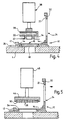
- the plate 201 is laid flat on a bed 214 of a porous material, with the non grooved face of the body upper most, and the upper surface of the plate 201 is covered with a layer of powdered medicament 216, which covers one end of each of the through bores.
- nitrogen is then passed down through the layer 216 of the through bores through the bed 214, causing the material 216 to pass into each of the through bores.
- the porosity of the bed 214 is such that it is impervious to the material 216. As a result, the bed 214 prevents material 216 being discharged from the bottom of the through bores.
- any excess material which has not been drawn into a through bore is removed by drawing a resiliently flexible blade 218 across the upper surface of the plate 201 ( Figure 1D).
- the sheet 204 is then heat sealed onto the upper surface of the plate 1 ( Figure 1E), which is then inverted so that the sheet 206 can be similarly applied to the opposite face of the plate 1 ( Figure 1F).
- the flexibility provided by the reduced thickness portions between the strips of the plate 201 enable the latter to be rolled (Figure 1G) into a generally cylindrical shape, with the strips extending axially along the cylinder, and the grooves 208 on the inner surface thereof.
- the container comprises a body 231 which is formed by rolling a plate (also referenced 231), and which has a number of through-bores eg 232 which are filled with powdered medicament by means of the same method as illustrated in Figure 1, and are sealed on one side by a first sheet of laminated foil 234 and on the other side by a second sheet of laminated foil 236 applied to the plate 231 after it has been inverted.
- the body 231 contains a larger number of through-bores, eg 232, than the body 201, and can therefore contain a greater number of doses of medicament than the body 201.
- each of the grooves in the plate 231, eg groove 238, is tapered so as to facilitate rolling.
- the caps 250 and 252 each include diametrically opposed inner slot arrangements, for example 256 and 258 which enable the container to be rotationally keyed to the rotational core or an inhaler in which the container is to be used.
- the through-bores are so arranged as to lie on a helical path on the body 231, when the container is assembled.
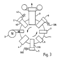
- the apparatus shown in Figure 3 comprises a carousel 1 and eight stations 2 - 9 positioned around the periphery thereof.
- the carousel rotates in an anti-clockwise direction to transport components on the carousel to each of the stations in turn, as described below.
- the apparatus includes a holder 10 for releasably retaining a container in the form of a rectangular plate.
- the holder 10 has a first rectangular frame portion 12 having an inner peripheral rectangular flange 14 which bounds a rectangular central opening 16. That gap accommodates a perforated metal block 18.
- the holder 10 also includes a second rectangular frame 20 which is pivotally mounted on the frame 12, and which also has a peripheral flange 22 and a central aperture 24.
- the holder 10 is releasably attached to the carousel 1 through an apertured plate 26.
- the station 2 includes a block 28 which has a central passage 30 which communicates with two feet 32 and 34.
- the passage 30 is selectably connected to a source of vacuum, and the block 28 is mounted on a pneumatic piston and cylinder assembly 38 which is operable to raise and lower the block 28.
- the piston and cylinder assembly 38 is, in turn, suspended from an upper plate 40 ( Figure 3) through drive means (not shown) operable to move the assembly 38, and hence the block 28, radially.
- a reel 42 of filter paper is provided at the radial outer end of the station 2, which includes a punch and die mechanism (not shown) for cutting the filter paper to length.
- the block 28 in use, retrieves a cut-out for filter paper from the radial outer end of the station 2, a vacuum being applied to the passage 30 to retain the cut-out on the feet 32 and 34, conveys it radially inwards to the position shown in Figure 4, and then lowers the filter paper onto the block 18. The vacuum is then disconnected so that when the block is raised, the filter paper remains in the holder 10.
- the holder 10 is then conveyed on the carousel 1 to the station 3, which is shown in more detail in Figure 5.
- the station 3 has a pneumatic gripper 44 which is mounted on an upper plate 46 through a pneumatic piston and cylinder assembly 48, which, use, the gripper 44 collects a container 50 from a magazine 52 at the radial outer end of the station 3, conveys the container 50 to the position shown in Figure 5 and places it in the holder 10 on the filter paper (referenced 54).
- the gripper 44 is then removed and the frame 20 is lowered onto the frame 12 so that the filter paper 54 and container 50 are clamped between the flanges 14 and 22.
- the container 50 comprises a flexible plate having an array of apertures, one of which is referenced 56.
- the container is similar to the containers shown in Figures 1A and 2A.
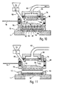
- the filling station 4 comprises a filling head 59 having a rectangular inlet manifold 58 which communicates with a pipe 60 through which pressurised nitrogen can be selectively supplied to the manifold.
- the manifold 58 is sealed against a rectangular upper frame portion 62 by an o-ring seal 64.
- the portion 62 includes a central rectangular opening which accommodates a diffuser 64a in the form of a perforated block, a peripheral rectangular frame portion 66 surrounds the portion 62, and defines, with the portion 62, a first end aperture which accommodates an inlet chute 68, along which powdered medicament is supplied, in use, from an auger 70 via valve 72.
- the frames 62 and 66 also define an aperture opposite said chute 68 for accommodating an ultrasonic level sensor 74.
- the peripheral frame includes a further aperture in one side thereof through which a rod 76 extends. The end of the rod is attached to a rectangular plate 79, the elongate axis of which extends substantially perpendicular
- a hopper 78 is sealed against the base of the frame 66 to an o-ring seal 80.
- the bottom of the hopper 78 includes a linear array of holes, one of which is denoted 82 which are in positions corresponding to the positions of the apertures in the container 50.
- the assembly positioned above the holder 10 in container 50 can be lowered into the position shown in Figures 8 and 9, in which the bottom of the hopper 78 closely abuts the contained 50, and the holes in the hopper 78 register with the apertures in the container 50.
- Powdered medicament 84 is then introduced into the hopper through the chute 68.
- the detector 74 then senses the level of the medicament 84 at the end of the hopper opposite the chute 68, and if that level is insufficient, the rod 76 is extended, causing the plate 79 to redistribute the medicament 84 over the holes in the hopper.
- Nitrogen is then introduced through the pipe 60, and passes through the diffuser 64a (which prevents the flow of nitrogen adversely affecting the distribution of the particulate material 84) through the material 84, the holes in the bottom of the hopper 78 and through the apertures in the container 50. Nitrogen exiting the apertures in the container 50 passes through the block 18 via the filter paper 54. This passage of nitrogen urges the powdered medicament 84 through the holes in the hopper 78 and into the apertures in the container 50, whilst the filter paper 54 prevents the powdered medicament being expelled through the bottom of the apertures.
- the filling head 59 is then raised from the container 50 as shown in Figure 11, and a further charge of powdered medicament is poured into the hopper for the next filling, and if necessary levelled by the plate 79.
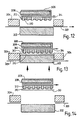
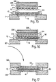
- the filled container 50 and its holder 10 are then transported by the carousel 1 to the station 5 which includes, at its radial outer end, a reel 300 of a web 302 of foil laminate, and feed-means (not shown) for feeding foil from the reel past a punch 302 and a die 304, which die defines a rectangular aperture.
- a sealing head 306 is mounted at the same end of the station 5, in registry with the aperture defined by the die 304 by means of a pneumatic piston and cylinder assembly (not shown) which is operable to raise and lower the head 306.
- the head 306 includes a heater 308 and a number of feet, one of which is referenced 310, arranged in a rectangular array at the underside of the head 306.
- Each foot is in the form of a short hollow cylinder, the interior of which communicates with a vertical passage, for example 312.
- the vertical passages in turn, communicate with a horizontal common passage 314 which is selectively connectable to a vacuum source (not shown).
- the punch 302 is also mounted on a pneumatic piston cylinder arrangement (not shown) which is operable to raise the punch 302, causing it to cut from the length of foil 301 a rectangular piece 313 which is moved up into contact with the head 306.
- the passage 314 is connected to the vacuum source which causes the feet on the head 306 to hold the piece 313 thereon.
- the web of foil 301 is wider than the cut-out 313, and as a result, when the punch 302 is returned to the position shown in Figure 13, a fresh piece of foil can be drawn into position above the punch 302 by means of a reel assembly (not shown) positioned to the right of the components shown in Figure 12, which is on the opposite side of those components from the reel 300.
- the piston and cylinder assembly on which the head 306 is mounted is mounted on a top plate 316 ( Figure 3) via a drive mechanism for moving the head 306 in either radial direction.
- a drive mechanism for moving the head 306 in either radial direction.
- the head 306 is then lowered onto the container 50 as shown in Figure 16.
- the foil laminate of the cut-out 313 has an upper layer (in contact with the feet on the head 306) which is substantially unaffected by the heat from the heater. However, the lowermost layer of the laminate is partially fused by the heat from the heater 308, causing the cut-out 313 to be heat-sealed to the container 50.
- the passage 314 is then disconnected from the vacuum supply, and the head 306 is raised and returned to the position shown in Figure 12, leaving the contained 50 with a foil laminate seal on one face.
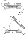
- the container 50 and its holder 10 are then transported to the station 6 at which the container 50, the support 10 and the plate 18 are removed from the carousel 1 and placed on a support block 320.
- a similar support block 322 and perforated plate 324 are then placed on top of the container 50 and holder 10.
- the supports 320 and 322 are connected to a mechanism (not shown) which inverts the elements shown in Figure 17 in the way indicated by the arrows 326 in Figure 18 so that the block 320 is then uppermost.
- the components shown in Figure 18 are then transported to the station 7 which includes a head (not shown) which releasably grips the top of the support 320 and which has a suction mechanism which seals against the plate 324, to cause the filter paper 54 to be held against the plate 18.
- the head is then moved away from the container 50, taking the block 320, the plate 18 and the paper 54 with it, as shown in Figure 19.
- the remaining elements shown in Figure 19 are then transported to the station 8 which is similar in form and function to the station 5, and which thus includes a reel 326 of foil laminate which is fed to a punch and die assembly similar to the punch and die 304 and 302.
- the punch and die cut out a piece of the foil laminate which is then applied to a head 328 of the same kind as the head 306.
- the head 328 is mounted at the station 7 by a similar arrangement used to mount the head 306 on the station 5, so that the head 328 can move radially into the position shown in Figure 20 in which is is directly above the container 50.
- the head is then lowered, sealing the cut out piece of foil laminate to the container 50.
- Figure 21 shows the container 50 in its filled and sealed form, still in its holder 10.
- the sheets of foil laminate are referenced 321 and 323.
- the container 50 and holder 10 are fed to the station 9 at which the container 50 is removed from the holder 10 and rolled into the form of a cylinder in a similar fashion to the method previously described.
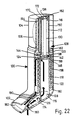
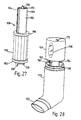
- an inhaler in which the container 50 can be used comprises a housing 100 which has a generally cylindrical portion and which is connected at its lower end to a mouth piece 102 extending substantially radially to the main body of the housing 100.
- the opposite end of the housing 100 includes a rotary member in the form of a cap 104 rotably mounted on the rest of the housing 100.
- the cap 104 incorporates a window 106 through which a cartridge 108 contained within the body 100 can be viewed.
- the cartridge 108 comprises a hollow cylindrical core 110 which has a reduced diameter upper portion 112 in which there is provided an upper aperture 114 and an integral tang 116.
- the core 110 also includes a lower portion 118 which is of a larger diameter than the portion 112, and which defines an annular shoulder 120 where it meets the portion 112.
- the portion 118 includes an external screw thread 122, a radial aperture 124 in its upper region, and two axially extending lower lugs 126 and 128.
- the core 110 accommodates a vertical shaft 130, the upper part of which protrudes through the aperture 114.
- the top of the shaft 130 includes a slot 132 for engaging a protuberance 136 on the underside of the top of the cap 104 so as to provide a rotational key between the shaft 130 and the cap 104.
- the bottom of the shaft 130 is provided with a radial crank arm 138 which incorporates a radial slot 140 which slidably engages a boss 142 connected to a pin 144 positioned above a plate 146.
- the pin is in registry with an aperture (not shown) in the case 110 angularly spaced from the aperture 124.
- the plate 146 is, with the cartridge assembled, attached to the interior of the core by suitable means (not shown), and the pin 144 and plate 146 include guide means (not shown) so arranged that rotation of the shaft 132 causes axial motion of the pin 144.
- the shoulder 120 supports a sleeve 150 which is rotably mounted on the core 110 and which surrounds the upper part 112.
- the sleeve 150 includes internal longitudinal serrations 152 and two diametrically opposed sets of external longitudinal ribs 154 and 156.
- the medicament to be dispensed is contained in a cylindrical container 158 which has side walls which include a number of helically arranged radial through bores such as 159 ( Figures 5 and 13), each of which contains a respective dose of material.
- the internal and external surfaces of the side walls are coated with corresponding sheets of a laminated foil which seals both ends of each bore.
- the container 158 is made by any one of the methods previously described.
- the core 110 extends through the centre of the container 158 which includes a lower end cap 160 having a part helical groove (not shown) for engaging the thread 122, and an upper cap 162 which includes two diametrically opposed sets of slots 164 and 166 which engage the sets of ribs 154 and 156 to provide a rotational key between the sleeve 150 and the container 158.
- the upper portion of the shaft 130 includes a shoulder 133 which supports a ratchet member 168 which is rotatable with respect to the shaft 130.
- the ratchet member 168 includes an upper boss 170 which engages in an arcuate track 172 ( Figure 28A) in the underside of the cap 104 to provide a lost motion connection between the cap 104 and the ratchet member 168.
- the cap 104 is removable from the rest of the housing 100 to enable the assembled cartridge 108 (as shown in Figure 10) to be inserted into the housing 100 until the lower lugs 126 and 128 of the core 110 engage in corresponding sockets 174, 176 ( Figure 23) in the bottom of the housing 100 to provide a rotational key between the core 110 and the housing 100.
- the housing 100 includes an upper rebate 178 which cooperates with a downwardly projecting lug (not shown) in the cap 104 to provide stops which define the limits of allowable rotational movement of the cap 104 relative to the rest of the housing 100.
- the lugs 126 and 128 space the lower end of the core 110 from the housing 100, thereby enabling the interior of the core 110 to communicate with an air inlet 180 provided in the underside of the mouthpiece 102, which includes an air outlet 182 partitioned from the inlet 180.
- the container 158 is spaced from the housing 100 so as to provide an outlet passage between vertical inner ribs 182 and 184 ( Figure 29A) which communicates with the outlet 182.
- the inhaler includes an airway, indicated by the marked arrows, extending from the air inlet 180 up through the core 110, through the aperture 124 and a dose containing through-bore in registry therewith and then through the outlet passage down to the outlet 182.
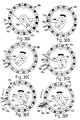
- the user In order to take a dose of medicament from the inhaler, the user must rotate the cap 104 from one to the other of its end positions and back again, causing the pin 144 to rupture the foil seal for a through bore and causing the through bore subsequently to be moved into registry with the outlet passage. This operation will now be described in greater detail with reference to Figures 29A-29F, and Figures 30A-30F.
- Figure 29A shows the dispenser in a initial condition in which the pin 144 is retracted and all the compartments are sealed.
- Rotation of the knob 104 in a clockwise direction as indicated by the arrow 184 of Figure 29B causes a corresponding rotation of the shaft 130 which, in turn, rotates the crank arm 138 so as to extend the pin 144 until it penetrates the inner seal of a cavity 186 ( Figure 30B).
- the slot 172 travels relative to the pin 170 so as to prevent rotation of the ratchet member 168 until the pin 170 engages the trailing end of the slot 172.
- the knob 104 is then rotated in the opposite direction as shown in Figure 30d, causing the pin 144 to be withdrawn from the bore 186.
- the slot 172 moves relative to the boss 170 so as to prevent corresponding movement of the sleeve 150 (and hence the container 158) until the pin 144 has been fully withdrawn.
- Further anticlockwise rotation of the knob 104 rotates the member 168, through the engagement of the boss 117 slot 172, in turn causing rotation of the sleeve 150.
- the mouthpiece 102 also includes a grille 190 for capturing any loose fragments of the sealing foil which come adrift during inhalation.
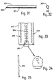
- the pin 144 is of the kind shown in Figures 31 and 32, and is so shaped as to create flaps in the foil seals whilst minimising the amount of material ejected from compartments during insertion. Those flaps are able to move, to allow material to be discharged, but are connected to the rest of the foil so as to reduce the chances of foil fragments breaking free during inhalation.
- FIG 33 An alternative type of container for powdered medicament is shown in Figure 33, and comprises a single rigid plate 350 having a central line of ten apertures such as the aperture 352, each of which contains a respective dose of medicament.
- the apertures are sealed by two strips of foil, one of which is denoted by reference 354 which extend along opposite of the plate 350.
- the medicament containing holes are flanked by two 356 and 358 of further holes which help to locate the plate 350 in use.
- the central holes in the plate 350 can be filled by the apparatus shown in Figures 3 - 21, when modified so that the number and position of holes in the hopper at the filling station correspond to the number and position of holes in the central line in the container 350.
- the modified apparatus lacks the rolling station 9 of the previously described apparatus.
Landscapes
- Health & Medical Sciences (AREA)
- Engineering & Computer Science (AREA)
- Public Health (AREA)
- General Health & Medical Sciences (AREA)
- Pulmonology (AREA)
- Anesthesiology (AREA)
- Biomedical Technology (AREA)
- Heart & Thoracic Surgery (AREA)
- Hematology (AREA)
- Life Sciences & Earth Sciences (AREA)
- Animal Behavior & Ethology (AREA)
- Bioinformatics & Cheminformatics (AREA)
- Veterinary Medicine (AREA)
- Mechanical Engineering (AREA)
- Medical Preparation Storing Or Oral Administration Devices (AREA)
- Basic Packing Technique (AREA)
- Processes Of Treating Macromolecular Substances (AREA)
- Containers And Packaging Bodies Having A Special Means To Remove Contents (AREA)
- Vacuum Packaging (AREA)
- Glass Compositions (AREA)
- Filling Or Emptying Of Bunkers, Hoppers, And Tanks (AREA)
- Superconductors And Manufacturing Methods Therefor (AREA)
- Transition And Organic Metals Composition Catalysts For Addition Polymerization (AREA)
- Supplying Of Containers To The Packaging Station (AREA)
- Physical Or Chemical Processes And Apparatus (AREA)
- Materials For Medical Uses (AREA)
- Closures For Containers (AREA)
Claims (14)
- Verfahren zum Befüllen eines Behälters (201; 231; 350), der mehrere Fächer (56; 202; 232; 352) hat, mit mehreren Dosen einer festgelegten Menge eines teilchenförmigen Materials, wobei das Verfahren die Schritte unfasst, dass manA. jedes der Fächer (56; 202; 232; 352) in eine Lage bringt, in der sie mit einem Vorrat (216; 84) einer mehr als ausreichenden Menge an teilchenförmigem Material in Verbindung stehen;B. das Material (216; 84) in die Fächer (56; 202; 232; 352) eintreten und diese füllen lässt; undC. die gefüllten Fächer (56; 202; 232; 352) von dem Vorrat (216; 84) trennt, wobei jede Dosis in einem entsprechenden Fach enthalten ist und das Volumen eines jeden Faches die Größe der darin enthaltenen Dosis bestimmt; dadurch gekennzeichnet, dass das teilchenförmige Material durch einen Gasdruck, der auf das teilchenförmige Material im Vorrat einwirkt, in die Fächer gedrückt wird, die durch Öffnungen in einer Platte gebildet werden, während der Behälter auf einer porösen Unterlage (214; 54; 18) ruht, die Gas aus den Öffnungen entweichen lässt, gleichzeitig aber verhindert, dass teilchenförmiges Material durch die Öffnungen ausgestoßen wird.
- Verfahren nach Anspruch 1, in dem das teilchenförmige Material ein pulverförmiges Arzneimittel ist, das durch Inhalieren verabreicht werden soll.
- Verfahren nach einem der vorhergehenden Ansprüche, in dem die Fächer (56; 202; 232; 352) vor dem Füllen in eine Lage gebracht werden, in der sie gleichzeitig mit einem gemeinsamen Vorrat (216; 84) in Verbindung stehen.
- Verfahren nach den vorhergehenden Ansprüchen, in dem die Fächer (56; 202; 232; 352) durch besagte Öffnungen in besagter Platte gebildet werden und Relativbewegung zwischen der Platte und dem Vorrat das Fach mit dem Vorrat in Verbindung bringt.
- Verfahren nach den vorhergehenden Ansprüchen, in dem die Unterlage (54; 18) eine perforierte Bodenplatte (18) mit darauf einem Blatt (54) eines feinporösen Materials umfasst, wobei das Blatt nach Gebrauch verworfen wird.
- Verfahren nach den vorhergehenden Ansprüchen, in dem die Fächer (56; 202; 232; 352) nach dem Füllen versiegelt werden, so dass jede Dosis einzeln in ihrem jeweiligen Fach eingeschlossen ist.
- Verfahren nach Anspruch 6 wenn abhängig von Anspruch 4, in dem die besagte Versiegelung durch das Auflaminieren von Blattmaterial (204; 206; 313; 321) auf beide Seiten der Platte erreicht wird.
- Verfahren nach Anspruch 7, in dem die Platte biegsam ist und nach dem Füllen aufgerollt oder auf andere Weise zu einem Zylinder geformt wird.
- Verfahren nach den vorhergehenden Ansprüchen, in dem sich der Vorrat in einem Vorratsbehälter (78) mit einer Reihe von Ausgabelöchern (82) befindet, die zum Füllen jeweils mit einem entsprechenden Fach (56) im Register sind, und das besagte Gas dem Vorratsbehälter unter einem ausreichenden Druck zugeführt wird, um das teilchenförmige Material durch die Ausgabelöcher (82) in die Öffnungen (56) zu drücken.
- Verfahren nach Anspruch 9, in dem die Abmessungen der Ausgabelöcher (82) so gewählt sind, dass sie das teilchenförmige Material im Wesentlichen daran hindern, die Löcher zu passieren, wenn es nicht durch Gasdruck hindurchgedrückt wird.
- Vorrichtung zur Durchführung eines Verfahrens nach Anspruch 1, wobei die Vorrichtung eine Unterlage (214; 54; 18) aus porösem Material, auf der die Platte glatt aufliegen kann, einen Füllkopf (59) für die Zufuhr von teilchenförmigem Material (84) zur Oberseite der Platte und Mittel zum Durchleiten von Luft oder einem Gas durch die Öffnungen in der Platte und die Unterlage, um teilchenförmiges Material in besagte Öffnungen zu drücken, umfasst.
- Vorrichtung nach Anspruch 11, in der der Füllkopf (59) einen Vorratsbehälter (78) mit einer Reihe von Ausgabelöchern (82) umfasst, deren relative Lage der der Öffnungen in der Platte (50) entspricht, so dass, wenn sich die Platte unter dem Vorratsbehälter befindet, jedes Ausgabeloch an einer entsprechenden Öffnung (56) ausgerichtet ist.
- Vorrichtung nach Anspruch 12, in der die Vorrichtung Mittel zur Füllstandserfassung (74) zur Feststellung des Füllstands des noch im Vorratsbehälter vorhandenen teilchenförmigen Materials und Zufuhrmittel (70; 72) für die Zufuhr von weiterem teilchenförmigen Material zum Vorratsbehälter beinhaltet.
- Vorrichtung nach Anspruch 13, in der der Vorratsbehälter länglich ist und die Mittel zur Füllstandserfassung (74) und die Zufuhrmittel (70, 72) so angebracht sind, dass Material an einem Ende des Vorratsbehälters (78) zugeführt wird und der Materialfüllstand in einem entfernten Bereich des Vorratsbehälters erfasst wird, wobei die Vorrichtung weiterhin Mittel (76) zur Verteilung von teilchenförmigem Material innerhalb des Vorratsbehälters beinhaltet, um darin eine im Wesentlichen gleichmäßige Tiefe zu erzielen.
Priority Applications (1)
| Application Number | Priority Date | Filing Date | Title |
|---|---|---|---|
| SI9530634T SI0751795T1 (en) | 1994-05-17 | 1995-05-16 | Method and apparatus for loading containers of particulate material |
Applications Claiming Priority (3)
| Application Number | Priority Date | Filing Date | Title |
|---|---|---|---|
| GB9409851A GB9409851D0 (en) | 1994-05-17 | 1994-05-17 | Improvements in and relating to containers of particulate material |
| GB9409851 | 1994-05-17 | ||
| PCT/GB1995/001105 WO1995031239A1 (en) | 1994-05-17 | 1995-05-16 | Improvements in and relating to containers of particulate material |
Publications (3)
| Publication Number | Publication Date |
|---|---|
| EP0751795A1 EP0751795A1 (de) | 1997-01-08 |
| EP0751795B1 true EP0751795B1 (de) | 2002-10-16 |
| EP0751795B8 EP0751795B8 (de) | 2003-03-19 |
Family
ID=10755262
Family Applications (1)
| Application Number | Title | Priority Date | Filing Date |
|---|---|---|---|
| EP95918690A Expired - Lifetime EP0751795B8 (de) | 1994-05-17 | 1995-05-16 | Verfahren und vorrichtung zum befüllem von pulverbehältern |
Country Status (18)
| Country | Link |
|---|---|
| US (1) | US6226962B1 (de) |
| EP (1) | EP0751795B8 (de) |
| JP (1) | JP3597197B2 (de) |
| KR (1) | KR100347467B1 (de) |
| CN (1) | CN1098713C (de) |
| AT (1) | ATE226101T1 (de) |
| AU (1) | AU697927B2 (de) |
| BR (1) | BR9507731A (de) |
| CA (1) | CA2190497C (de) |
| DE (1) | DE69528579T2 (de) |
| DK (1) | DK0751795T3 (de) |
| ES (1) | ES2187558T3 (de) |
| FI (1) | FI964594L (de) |
| GB (1) | GB9409851D0 (de) |
| HU (1) | HU219111B (de) |
| PT (1) | PT751795E (de) |
| RU (1) | RU2141914C1 (de) |
| WO (1) | WO1995031239A1 (de) |
Families Citing this family (40)
| Publication number | Priority date | Publication date | Assignee | Title |
|---|---|---|---|---|
| GB9911770D0 (en) * | 1999-05-21 | 1999-07-21 | Glaxo Group Ltd | Powder loading method |
| GB9523555D0 (en) * | 1995-11-17 | 1996-01-17 | Cambridge Consultants | Filling containers with particulate material |
| US5794613A (en) * | 1997-01-09 | 1998-08-18 | Sepracor, Inc. | Multiple-dose dispenser for dry powder inhalers |
| FR2768123B1 (fr) * | 1997-09-09 | 1999-11-26 | Soc Generale Pour Les Techniques Nouvelles Sgn | Procede et dispositif de conditionnement de produits, tel des poudres, notamment magnetiques |
| GB0023653D0 (en) * | 2000-09-27 | 2000-11-08 | Cambridge Consultants | Device for dispensing particulate material |
| US7621300B2 (en) * | 2001-04-20 | 2009-11-24 | Glaxo Group Limited | Metering method for particulate material |
| GB0202912D0 (en) * | 2002-02-07 | 2002-03-27 | Meridica Ltd | Method and apparatus for introducing powder into a pocket |
| GB0207769D0 (en) | 2002-04-04 | 2002-05-15 | Glaxo Group Ltd | Method and apparatus for loading a container with a product |
| SI1535349T1 (sl) | 2002-06-27 | 2014-10-30 | Oriel Therapeutics, Inc. | Naprave, sistemi in ustrezni postopki za predelavo, izdajo in/ali vrednotenje nefarmacevtskih suhih praškov |
| GB0227128D0 (en) * | 2002-11-20 | 2002-12-24 | Glaxo Group Ltd | A capsule |
| RU2363502C2 (ru) * | 2004-02-06 | 2009-08-10 | Майкродоуз Текнолоджиз, Инк. | Блистерная упаковка, предназначенная для применения с ингаляционным устройством |
| DE202005004188U1 (de) * | 2005-03-14 | 2005-05-19 | Harro Höfliger Verpackungsmaschinen GmbH | Vorrichtung zum Abfüllen von jeweils vorbestimmt großen Mengen an pulvrigem Füllgut |
| US9485917B2 (en) | 2006-12-15 | 2016-11-08 | Ecovative Design, LLC | Method for producing grown materials and products made thereby |
| WO2009008832A1 (en) * | 2007-07-12 | 2009-01-15 | Astrazeneca Ab | Medicament containing structure, method and inhalation device comprising such structure |
| ES2702753T3 (es) | 2010-01-05 | 2019-03-05 | Microdose Therapeutx Inc | Dispositivo de inhalación |
| US8720497B2 (en) | 2010-02-19 | 2014-05-13 | Oriel Therapeutics, Inc. | Direct fill dry powder systems with dosing heads configured for on/off controlled flow |
| US8776840B2 (en) * | 2010-02-23 | 2014-07-15 | Oriel Therapeutics, Inc. | Tubular dry powder feeders with axially applied vibration for dry powder filling systems |
| CN102161384B (zh) * | 2011-03-07 | 2012-07-04 | 汪明霞 | 一种颗粒谷物收储器 |
| US20140056653A1 (en) * | 2012-08-22 | 2014-02-27 | Christopher Scully | Method and Machine for Filling 3D Cavities with Bulk Material |
| CN102795588A (zh) * | 2012-08-31 | 2012-11-28 | 常熟市百联自动机械有限公司 | 一种充绒机的充绒方法 |
| CN102815656B (zh) * | 2012-08-31 | 2014-07-16 | 常熟市百联自动机械有限公司 | 一种充绒机的精确充绒方法 |
| US11277979B2 (en) | 2013-07-31 | 2022-03-22 | Ecovative Design Llc | Mycological biopolymers grown in void space tooling |
| US20150101509A1 (en) | 2013-10-14 | 2015-04-16 | Gavin R. McIntyre | Method of Manufacturing a Stiff Engineered Composite |
| WO2016168563A1 (en) | 2015-04-15 | 2016-10-20 | Ecovative Design Llc | Process for production of mycelial composite surfaces in a roll-to-roll format |
| CN105030544B (zh) * | 2015-06-20 | 2019-02-15 | 浙江天龙胶丸有限公司 | 一种胶囊自动填充套合一体机 |
| CN109153964B (zh) | 2016-03-01 | 2023-06-13 | 芬德集团公司 | 丝状真菌生物垫、及其生产方法和使用方法 |
| DE102016119191A1 (de) * | 2016-10-10 | 2018-04-12 | Haver & Boecker Ohg | Fülleinrichtung für eine Packmaschine zum Füllen von Schüttgütern in Gebinde |
| WO2018090902A1 (zh) * | 2016-11-15 | 2018-05-24 | 正大天晴药业集团股份有限公司 | 用于粉末填充的设备及方法 |
| US10414148B2 (en) | 2016-11-16 | 2019-09-17 | United Technologies Corporation | Selective powder dosing for an additively manufacturing system |
| CN117987277A (zh) | 2017-03-31 | 2024-05-07 | 生态创新设计有限责任公司 | 用于真菌生物聚合物材料的基于溶液的后加工方法和由此制备的真菌产品 |
| US11266085B2 (en) | 2017-11-14 | 2022-03-08 | Ecovative Design Llc | Increased homogeneity of mycological biopolymer grown into void space |
| RU2759489C1 (ru) * | 2018-01-31 | 2021-11-15 | Синтегон Текнолоджи Гмбх | Устройство для дозирования продукта |
| US11920126B2 (en) | 2018-03-28 | 2024-03-05 | Ecovative Design Llc | Bio-manufacturing process |
| US11293005B2 (en) | 2018-05-07 | 2022-04-05 | Ecovative Design Llc | Process for making mineralized mycelium scaffolding and product made thereby |
| US20190359931A1 (en) | 2018-05-24 | 2019-11-28 | Ecovative Design Llc | Process and Apparatus for Producing Mycelium Biomaterial |
| CN109010065A (zh) * | 2018-07-30 | 2018-12-18 | 吴霞 | 一种多功能肿瘤科用碎药装置 |
| US11359174B2 (en) | 2018-10-02 | 2022-06-14 | Ecovative Design Llc | Bioreactor paradigm for the production of secondary extra-particle hyphal matrices |
| EP3990353A1 (de) * | 2019-06-25 | 2022-05-04 | Mylan Pharma UK Limited | Füllkopf für die angetriebene schichtung eines trockenpulverinhalators |
| EP4334432A1 (de) | 2021-05-04 | 2024-03-13 | Ecovative Design LLC | Luftmyzelien und verfahren zur herstellung davon |
| CN113859656B (zh) * | 2021-09-17 | 2023-06-13 | 湖北亿家艾生物科技有限公司 | 眼罩原料封装单元及眼罩制造设备 |
Family Cites Families (25)
| Publication number | Priority date | Publication date | Assignee | Title |
|---|---|---|---|---|
| US2550070A (en) * | 1945-06-29 | 1951-04-24 | Hilliard Corp | Method of making filter units |
| US3103774A (en) * | 1961-12-22 | 1963-09-17 | Tibor H Wall | Packaging means |
| US3208192A (en) * | 1962-09-06 | 1965-09-28 | Procter & Gamble | Formation of firm flat packets of granular substance |
| US3349814A (en) * | 1965-05-12 | 1967-10-31 | James E Webb | Method and apparatus for making a heat insulating and ablative structure |
| US3324902A (en) * | 1965-05-26 | 1967-06-13 | Bartelt Engineering Co Inc | Method of filling capsules |
| US3686822A (en) * | 1970-09-14 | 1972-08-29 | Young William E | Apparatus and method for skin packaging |
| US4219987A (en) * | 1979-03-26 | 1980-09-02 | Diversified Packaging, Incorporated | Method for skin packaging using platen forming of the film, and packages produced thereby |
| US4418511A (en) * | 1980-06-13 | 1983-12-06 | Nordson Corporation | Apparatus and method for film packaging |
| US4415085A (en) * | 1981-12-21 | 1983-11-15 | Eli Lilly And Company | Dry pharmaceutical system |
| NO160330C (no) * | 1982-10-08 | 1989-04-12 | Glaxo Group Ltd | Anordning for aa administrere medikamenter til pasienter og medikamentpakning for anordningen. |
| CA1259966A (en) * | 1985-02-27 | 1989-09-26 | Taizo Yamamoto | Capsule filling apparatus |
| CA1264705A (en) * | 1985-03-15 | 1990-01-23 | Luigi Bertolotti | Wrapper for ribbon type metal coils, and procedure for forming it |
| US4733449A (en) * | 1985-07-15 | 1988-03-29 | Spearman Michael R | Spin connection adsorption filter and method of making same |
| US4811731A (en) * | 1985-07-30 | 1989-03-14 | Glaxo Group Limited | Devices for administering medicaments to patients |
| LU86048A1 (fr) * | 1985-08-21 | 1987-03-06 | Wurth Paul Sa | Dispositif pour l'injection pneumatique de matieres pulverulentes dans une enceinte sous pression et application a l'injection de combustibles solides dans un four a cuve |
| DE3708933A1 (de) * | 1987-03-19 | 1988-09-29 | Heinrich Prof Dr Ing Reents | Verfahren mit den dazu gehoerigen vorrichtungen zur dosierung feiner und fester werkstoff- und wirkstoffteilchen mit hilfe schwingungserzeugender systeme |
| US4955412A (en) * | 1989-03-29 | 1990-09-11 | Continental American Corporation | Apparatus for injecting confetti into a balloon |
| US5271209A (en) * | 1990-05-11 | 1993-12-21 | Gradual Pty. Ltd. | Packaging process and apparatus |
| IT1243344B (it) * | 1990-07-16 | 1994-06-10 | Promo Pack Sa | Inalatore plurimonodose per medicamenti in polvere |
| FR2667790A1 (fr) * | 1990-10-04 | 1992-04-17 | Valois | Cassette de conditionnement de microdoses de poudre sous forme de bandes adaptees a etre utilisees dans un inhalateur a poudre, et son procede de fabrication. |
| IT1248059B (it) * | 1991-06-14 | 1995-01-05 | Miat Spa | Insufflatore multidose per farmaci in polvere |
| GB9203761D0 (en) * | 1992-02-21 | 1992-04-08 | Innovata Biomed Ltd | Inhaler |
| US5769073A (en) * | 1993-12-18 | 1998-06-23 | Merck Patent Gesellschaft Mit Beschrankter Haftung | Powder inhalator |
| GB9409852D0 (en) * | 1994-05-17 | 1994-07-06 | Cambridge Consultants | Device for administering single doses of a medicament |
| GB9523555D0 (en) * | 1995-11-17 | 1996-01-17 | Cambridge Consultants | Filling containers with particulate material |
-
1994
- 1994-05-17 GB GB9409851A patent/GB9409851D0/en active Pending
-
1995
- 1995-05-16 DE DE69528579T patent/DE69528579T2/de not_active Expired - Fee Related
- 1995-05-16 WO PCT/GB1995/001105 patent/WO1995031239A1/en not_active Ceased
- 1995-05-16 KR KR1019960706496A patent/KR100347467B1/ko not_active Expired - Fee Related
- 1995-05-16 AU AU24520/95A patent/AU697927B2/en not_active Ceased
- 1995-05-16 DK DK95918690T patent/DK0751795T3/da active
- 1995-05-16 CN CN95193074A patent/CN1098713C/zh not_active Expired - Fee Related
- 1995-05-16 ES ES95918690T patent/ES2187558T3/es not_active Expired - Lifetime
- 1995-05-16 RU RU96123902A patent/RU2141914C1/ru not_active IP Right Cessation
- 1995-05-16 EP EP95918690A patent/EP0751795B8/de not_active Expired - Lifetime
- 1995-05-16 FI FI964594A patent/FI964594L/fi not_active Application Discontinuation
- 1995-05-16 CA CA002190497A patent/CA2190497C/en not_active Expired - Fee Related
- 1995-05-16 JP JP52946395A patent/JP3597197B2/ja not_active Expired - Fee Related
- 1995-05-16 BR BR9507731A patent/BR9507731A/pt not_active IP Right Cessation
- 1995-05-16 HU HU9603159A patent/HU219111B/hu not_active IP Right Cessation
- 1995-05-16 AT AT95918690T patent/ATE226101T1/de not_active IP Right Cessation
- 1995-05-16 PT PT95918690T patent/PT751795E/pt unknown
- 1995-05-17 US US08/442,676 patent/US6226962B1/en not_active Expired - Fee Related
Also Published As
| Publication number | Publication date |
|---|---|
| KR100347467B1 (ko) | 2003-01-29 |
| MX9605602A (es) | 1998-05-31 |
| FI964594A0 (fi) | 1996-11-15 |
| AU2452095A (en) | 1995-12-05 |
| DK0751795T3 (da) | 2003-01-06 |
| EP0751795B8 (de) | 2003-03-19 |
| HU9603159D0 (en) | 1997-01-28 |
| BR9507731A (pt) | 1997-08-19 |
| FI964594A7 (fi) | 1996-11-15 |
| HU219111B (hu) | 2001-02-28 |
| ATE226101T1 (de) | 2002-11-15 |
| WO1995031239A1 (en) | 1995-11-23 |
| AU697927B2 (en) | 1998-10-22 |
| PT751795E (pt) | 2003-03-31 |
| ES2187558T3 (es) | 2003-06-16 |
| CN1098713C (zh) | 2003-01-15 |
| EP0751795A1 (de) | 1997-01-08 |
| GB9409851D0 (en) | 1994-07-06 |
| DE69528579D1 (de) | 2002-11-21 |
| RU2141914C1 (ru) | 1999-11-27 |
| CA2190497A1 (en) | 1995-11-23 |
| CA2190497C (en) | 2005-06-28 |
| HUT76307A (en) | 1997-08-28 |
| JP3597197B2 (ja) | 2004-12-02 |
| CN1170368A (zh) | 1998-01-14 |
| US6226962B1 (en) | 2001-05-08 |
| JPH10503393A (ja) | 1998-03-31 |
| DE69528579T2 (de) | 2003-06-05 |
| FI964594L (fi) | 1996-11-15 |
Similar Documents
| Publication | Publication Date | Title |
|---|---|---|
| EP0751795B1 (de) | Verfahren und vorrichtung zum befüllem von pulverbehältern | |
| US5769073A (en) | Powder inhalator | |
| KR100430188B1 (ko) | 미립자물질의주입방법및장치 | |
| KR100264805B1 (ko) | 계량 장치 | |
| KR100352514B1 (ko) | 분말흡입기 | |
| US9974909B2 (en) | Inhalation device and method | |
| EP0759306B1 (de) | Vorrichtung zum Verabreichen von Medikamenten | |
| US6698425B1 (en) | Powder inhaler | |
| WO2005030305A1 (en) | Assembly for opening medicament containers, particularly containers for a powdered medicament | |
| MXPA96005602A (en) | Improvements related to particulate material containers | |
| HK1260175A1 (en) | Inhalation device and method | |
| HK1023076A (en) | An inhaler for delivering a substance in a finely divided form |
Legal Events
| Date | Code | Title | Description |
|---|---|---|---|
| PUAI | Public reference made under article 153(3) epc to a published international application that has entered the european phase |
Free format text: ORIGINAL CODE: 0009012 |
|
| 17P | Request for examination filed |
Effective date: 19961031 |
|
| AK | Designated contracting states |
Kind code of ref document: A1 Designated state(s): AT BE CH DE DK ES FR GB GR IE IT LI LU NL PT SE |
|
| RAP1 | Party data changed (applicant data changed or rights of an application transferred) |
Owner name: MERCK PATENT GMBH |
|
| GRAG | Despatch of communication of intention to grant |
Free format text: ORIGINAL CODE: EPIDOS AGRA |
|
| RTI1 | Title (correction) |
Free format text: METHOD AND APPARATUS FOR LOADING CONTAINERS OF PARTICULATE MATERIAL |
|
| 17Q | First examination report despatched |
Effective date: 20020228 |
|
| GRAG | Despatch of communication of intention to grant |
Free format text: ORIGINAL CODE: EPIDOS AGRA |
|
| GRAH | Despatch of communication of intention to grant a patent |
Free format text: ORIGINAL CODE: EPIDOS IGRA |
|
| RAP1 | Party data changed (applicant data changed or rights of an application transferred) |
Owner name: MERCK PATENT GMBH |
|
| GRAH | Despatch of communication of intention to grant a patent |
Free format text: ORIGINAL CODE: EPIDOS IGRA |
|
| GRAA | (expected) grant |
Free format text: ORIGINAL CODE: 0009210 |
|
| AK | Designated contracting states |
Kind code of ref document: B1 Designated state(s): AT BE CH DE DK ES FR GB GR IE IT LI LU NL PT SE |
|
| REF | Corresponds to: |
Ref document number: 226101 Country of ref document: AT Date of ref document: 20021115 Kind code of ref document: T |
|
| REG | Reference to a national code |
Ref country code: GB Ref legal event code: FG4D |
|
| REG | Reference to a national code |
Ref country code: CH Ref legal event code: EP |
|
| REG | Reference to a national code |
Ref country code: IE Ref legal event code: FG4D |
|
| REF | Corresponds to: |
Ref document number: 69528579 Country of ref document: DE Date of ref document: 20021121 |
|
| REG | Reference to a national code |
Ref country code: CH Ref legal event code: NV Representative=s name: BOVARD AG PATENTANWAELTE |
|
| REG | Reference to a national code |
Ref country code: DK Ref legal event code: T3 |
|
| DAX | Request for extension of the european patent (deleted) | ||
| REG | Reference to a national code |
Ref country code: GR Ref legal event code: EP Ref document number: 20030400096 Country of ref document: GR |
|
| RAX | Requested extension states of the european patent have changed |
Extension state: SI Payment date: 19961030 Extension state: LV Payment date: 19961030 Extension state: LT Payment date: 19961030 |
|
| REG | Reference to a national code |
Ref country code: PT Ref legal event code: SC4A Free format text: AVAILABILITY OF NATIONAL TRANSLATION Effective date: 20030115 |
|
| ET | Fr: translation filed | ||
| REG | Reference to a national code |
Ref country code: ES Ref legal event code: FG2A Ref document number: 2187558 Country of ref document: ES Kind code of ref document: T3 |
|
| PLBE | No opposition filed within time limit |
Free format text: ORIGINAL CODE: 0009261 |
|
| STAA | Information on the status of an ep patent application or granted ep patent |
Free format text: STATUS: NO OPPOSITION FILED WITHIN TIME LIMIT |
|
| 26N | No opposition filed |
Effective date: 20030717 |
|
| REG | Reference to a national code |
Ref country code: SI Ref legal event code: IF |
|
| PGFP | Annual fee paid to national office [announced via postgrant information from national office to epo] |
Ref country code: GR Payment date: 20050329 Year of fee payment: 11 |
|
| PGFP | Annual fee paid to national office [announced via postgrant information from national office to epo] |
Ref country code: FR Payment date: 20050427 Year of fee payment: 11 |
|
| PGFP | Annual fee paid to national office [announced via postgrant information from national office to epo] |
Ref country code: NL Payment date: 20050503 Year of fee payment: 11 |
|
| PGFP | Annual fee paid to national office [announced via postgrant information from national office to epo] |
Ref country code: ES Payment date: 20050504 Year of fee payment: 11 |
|
| PGFP | Annual fee paid to national office [announced via postgrant information from national office to epo] |
Ref country code: PT Payment date: 20050505 Year of fee payment: 11 |
|
| PGFP | Annual fee paid to national office [announced via postgrant information from national office to epo] |
Ref country code: SE Payment date: 20050506 Year of fee payment: 11 |
|
| PGFP | Annual fee paid to national office [announced via postgrant information from national office to epo] |
Ref country code: CH Payment date: 20050509 Year of fee payment: 11 |
|
| PGFP | Annual fee paid to national office [announced via postgrant information from national office to epo] |
Ref country code: IE Payment date: 20050511 Year of fee payment: 11 Ref country code: GB Payment date: 20050511 Year of fee payment: 11 Ref country code: AT Payment date: 20050511 Year of fee payment: 11 |
|
| PGFP | Annual fee paid to national office [announced via postgrant information from national office to epo] |
Ref country code: DE Payment date: 20050512 Year of fee payment: 11 |
|
| PGFP | Annual fee paid to national office [announced via postgrant information from national office to epo] |
Ref country code: DK Payment date: 20050513 Year of fee payment: 11 |
|
| PGFP | Annual fee paid to national office [announced via postgrant information from national office to epo] |
Ref country code: LU Payment date: 20050520 Year of fee payment: 11 |
|
| PGFP | Annual fee paid to national office [announced via postgrant information from national office to epo] |
Ref country code: BE Payment date: 20050715 Year of fee payment: 11 |
|
| PG25 | Lapsed in a contracting state [announced via postgrant information from national office to epo] |
Ref country code: IE Free format text: LAPSE BECAUSE OF NON-PAYMENT OF DUE FEES Effective date: 20060516 Ref country code: GB Free format text: LAPSE BECAUSE OF NON-PAYMENT OF DUE FEES Effective date: 20060516 Ref country code: AT Free format text: LAPSE BECAUSE OF NON-PAYMENT OF DUE FEES Effective date: 20060516 |
|
| PG25 | Lapsed in a contracting state [announced via postgrant information from national office to epo] |
Ref country code: SE Free format text: LAPSE BECAUSE OF NON-PAYMENT OF DUE FEES Effective date: 20060517 Ref country code: ES Free format text: LAPSE BECAUSE OF NON-PAYMENT OF DUE FEES Effective date: 20060517 |
|
| PG25 | Lapsed in a contracting state [announced via postgrant information from national office to epo] |
Ref country code: LI Free format text: LAPSE BECAUSE OF NON-PAYMENT OF DUE FEES Effective date: 20060531 Ref country code: DK Free format text: LAPSE BECAUSE OF NON-PAYMENT OF DUE FEES Effective date: 20060531 Ref country code: CH Free format text: LAPSE BECAUSE OF NON-PAYMENT OF DUE FEES Effective date: 20060531 Ref country code: BE Free format text: LAPSE BECAUSE OF NON-PAYMENT OF DUE FEES Effective date: 20060531 |
|
| PGFP | Annual fee paid to national office [announced via postgrant information from national office to epo] |
Ref country code: IT Payment date: 20060531 Year of fee payment: 12 |
|
| PG25 | Lapsed in a contracting state [announced via postgrant information from national office to epo] |
Ref country code: PT Free format text: LAPSE BECAUSE OF NON-PAYMENT OF DUE FEES Effective date: 20061116 |
|
| PG25 | Lapsed in a contracting state [announced via postgrant information from national office to epo] |
Ref country code: NL Free format text: LAPSE BECAUSE OF NON-PAYMENT OF DUE FEES Effective date: 20061201 Ref country code: DE Free format text: LAPSE BECAUSE OF NON-PAYMENT OF DUE FEES Effective date: 20061201 |
|
| REG | Reference to a national code |
Ref country code: CH Ref legal event code: PL Ref country code: DK Ref legal event code: EBP |
|
| EUG | Se: european patent has lapsed | ||
| GBPC | Gb: european patent ceased through non-payment of renewal fee |
Effective date: 20060516 |
|
| LTLA | Lt: lapse of european patent or patent extension |
Effective date: 20060516 |
|
| REG | Reference to a national code |
Ref country code: PT Ref legal event code: MM4A Free format text: LAPSE DUE TO NON-PAYMENT OF FEES Effective date: 20061116 |
|
| NLV4 | Nl: lapsed or anulled due to non-payment of the annual fee |
Effective date: 20061201 |
|
| REG | Reference to a national code |
Ref country code: FR Ref legal event code: ST Effective date: 20070131 |
|
| REG | Reference to a national code |
Ref country code: SI Ref legal event code: KO00 Effective date: 20070126 |
|
| REG | Reference to a national code |
Ref country code: ES Ref legal event code: FD2A Effective date: 20060517 |
|
| BERE | Be: lapsed |
Owner name: *MERCK PATENT G.M.B.H. Effective date: 20060531 |
|
| PG25 | Lapsed in a contracting state [announced via postgrant information from national office to epo] |
Ref country code: FR Free format text: LAPSE BECAUSE OF NON-PAYMENT OF DUE FEES Effective date: 20060531 |
|
| PG25 | Lapsed in a contracting state [announced via postgrant information from national office to epo] |
Ref country code: LU Free format text: LAPSE BECAUSE OF NON-PAYMENT OF DUE FEES Effective date: 20060516 |
|
| PG25 | Lapsed in a contracting state [announced via postgrant information from national office to epo] |
Ref country code: GR Free format text: LAPSE BECAUSE OF NON-PAYMENT OF DUE FEES Effective date: 20061205 |
|
| PG25 | Lapsed in a contracting state [announced via postgrant information from national office to epo] |
Ref country code: IT Free format text: LAPSE BECAUSE OF NON-PAYMENT OF DUE FEES Effective date: 20070516 |