EP0751060B1 - Deichsel für kraftgetriebene Flurförderzeuge - Google Patents
Deichsel für kraftgetriebene Flurförderzeuge Download PDFInfo
- Publication number
- EP0751060B1 EP0751060B1 EP96109729A EP96109729A EP0751060B1 EP 0751060 B1 EP0751060 B1 EP 0751060B1 EP 96109729 A EP96109729 A EP 96109729A EP 96109729 A EP96109729 A EP 96109729A EP 0751060 B1 EP0751060 B1 EP 0751060B1
- Authority
- EP
- European Patent Office
- Prior art keywords
- horn
- steering bar
- bar according
- grip
- switch
- Prior art date
- Legal status (The legal status is an assumption and is not a legal conclusion. Google has not performed a legal analysis and makes no representation as to the accuracy of the status listed.)
- Expired - Lifetime
Links
Images


Classifications
-
- G—PHYSICS
- G05—CONTROLLING; REGULATING
- G05G—CONTROL DEVICES OR SYSTEMS INSOFAR AS CHARACTERISED BY MECHANICAL FEATURES ONLY
- G05G1/00—Controlling members, e.g. knobs or handles; Assemblies or arrangements thereof; Indicating position of controlling members
- G05G1/01—Arrangements of two or more controlling members with respect to one another
-
- B—PERFORMING OPERATIONS; TRANSPORTING
- B62—LAND VEHICLES FOR TRAVELLING OTHERWISE THAN ON RAILS
- B62B—HAND-PROPELLED VEHICLES, e.g. HAND CARTS OR PERAMBULATORS; SLEDGES
- B62B3/00—Hand carts having more than one axis carrying transport wheels; Steering devices therefor; Equipment therefor
- B62B3/04—Hand carts having more than one axis carrying transport wheels; Steering devices therefor; Equipment therefor involving means for grappling or securing in place objects to be carried; Loading or unloading equipment
- B62B3/06—Hand carts having more than one axis carrying transport wheels; Steering devices therefor; Equipment therefor involving means for grappling or securing in place objects to be carried; Loading or unloading equipment for simply clearing the load from the ground
-
- B—PERFORMING OPERATIONS; TRANSPORTING
- B62—LAND VEHICLES FOR TRAVELLING OTHERWISE THAN ON RAILS
- B62B—HAND-PROPELLED VEHICLES, e.g. HAND CARTS OR PERAMBULATORS; SLEDGES
- B62B5/00—Accessories or details specially adapted for hand carts
- B62B5/06—Hand moving equipment, e.g. handle bars
-
- B—PERFORMING OPERATIONS; TRANSPORTING
- B62—LAND VEHICLES FOR TRAVELLING OTHERWISE THAN ON RAILS
- B62D—MOTOR VEHICLES; TRAILERS
- B62D51/00—Motor vehicles characterised by the driver not being seated
- B62D51/001—Motor vehicles characterised by the driver not being seated characterised by the vehicle control device
-
- B—PERFORMING OPERATIONS; TRANSPORTING
- B66—HOISTING; LIFTING; HAULING
- B66F—HOISTING, LIFTING, HAULING OR PUSHING, NOT OTHERWISE PROVIDED FOR, e.g. DEVICES WHICH APPLY A LIFTING OR PUSHING FORCE DIRECTLY TO THE SURFACE OF A LOAD
- B66F9/00—Devices for lifting or lowering bulky or heavy goods for loading or unloading purposes
- B66F9/06—Devices for lifting or lowering bulky or heavy goods for loading or unloading purposes movable, with their loads, on wheels or the like, e.g. fork-lift trucks
- B66F9/075—Constructional features or details
- B66F9/20—Means for actuating or controlling masts, platforms, or forks
-
- B—PERFORMING OPERATIONS; TRANSPORTING
- B62—LAND VEHICLES FOR TRAVELLING OTHERWISE THAN ON RAILS
- B62B—HAND-PROPELLED VEHICLES, e.g. HAND CARTS OR PERAMBULATORS; SLEDGES
- B62B2501/00—Manufacturing; Constructional features
- B62B2501/06—Materials used
- B62B2501/065—Plastics
-
- B—PERFORMING OPERATIONS; TRANSPORTING
- B62—LAND VEHICLES FOR TRAVELLING OTHERWISE THAN ON RAILS
- B62B—HAND-PROPELLED VEHICLES, e.g. HAND CARTS OR PERAMBULATORS; SLEDGES
- B62B5/00—Accessories or details specially adapted for hand carts
- B62B5/06—Hand moving equipment, e.g. handle bars
- B62B5/063—Hand moving equipment, e.g. handle bars for low-lift hand trucks
-
- H—ELECTRICITY
- H01—ELECTRIC ELEMENTS
- H01H—ELECTRIC SWITCHES; RELAYS; SELECTORS; EMERGENCY PROTECTIVE DEVICES
- H01H9/00—Details of switching devices, not covered by groups H01H1/00 - H01H7/00
- H01H9/02—Bases, casings, or covers
- H01H9/06—Casing of switch constituted by a handle serving a purpose other than the actuation of the switch, e.g. by the handle of a vacuum cleaner
- H01H2009/068—Casing of switch constituted by a handle serving a purpose other than the actuation of the switch, e.g. by the handle of a vacuum cleaner with switches mounted on a handlebar, e.g. for motorcycles, fork lift trucks, etc.
Definitions
- the invention relates to a drawbar for power-driven Industrial trucks according to the preamble of the claim 1.
- Pallet trucks or pallet trucks have a drawbar with which the conveyor is steered.
- the linkage the drawbar is on the bracket for the pivotable Drive wheel of the conveyor.
- a tiller head is provided, which has several actuators has to operate the conveyor.
- the latter include a travel switch, buttons for lifting and lowering, the horn and a body protection switch.
- Atlet Elektro-Deichselhubwagen has become known in an area of the horn that is in the area the support sections are turned towards the driver two opposite switch buttons to operate the To provide lifting and lowering operations.
- the shift buttons are actuated with the fingertip by applying pressure by stretching the finger is exercised (opening the hand on Handle).
- a drawbar for power-driven industrial trucks here a lift truck
- a drawbar for power-driven industrial trucks, here a lift truck
- They comprise rod-like handles extending on both sides of a horn in the extension of the drawbar, a drive switch handle pivotally mounted on the horn, which has a recess facing away from the handle for actuation with the thumb, the handles being connected to the outer ends of the handles and approximately parallel to the handle Horn-extending leg sections and are connected to the horn or the stem via support sections connected to the leg sections.
- the leg and support sections form a protective bracket with handle openings.
- Switching buttons are attached to both sides of the horn on a surface of the carrier sections, which slope at an angle to the vertical in the direction of the handles.
- the switch buttons for lifting and lowering are one above the other, so that the operator has to release the handle more or less when pressing one of these function buttons.
- the arrangement of the switch buttons is also such that they are by a Bump "or Drilling "must be actuated with the finger in the direction of the switch button. Such an actuation is ergonomically unfavorable and tiring.
- the invention has for its object a drawbar for power-driven industrial trucks to create, in which the tiller head is designed so that all operating functions can be operated easily and with one hand. About that In addition, a simultaneous actuation of several operating functions with only one Hand can be made without the operator's hand released from the handle must become.
- the switching buttons are arranged in a row next to one another in a surface that slopes away from the horn so that they can be ergonomically actuated by extending the finger of a hand gripping the handle in the direction of the natural gripping movement of the fingertip.
- three control buttons are arranged on each side of the horn, the control buttons preferably being rectangular buttons that protrude only slightly from the surface immediately adjacent.
- the switch button rows are not arranged parallel to the handle, but at an angle, enclosing an obtuse angle on both sides of the horn such that they diverge away from the handles.
- the surface containing the switch buttons is formed by a trough, which is between a leg portion and the Horn or the stem extends.
- the trough has both to the side, i. H. from the horn away, a slope as well as an inclination towards the operator.
- the switch buttons are preferably applied the preferably straight edge of the trough, which the handle opening in this area limited.
- the upper section is the horn raised compared to the plane which is formed from the handle and leg section, so that the switch button closest to the horn is slightly above the handle lies.
- the support sections are in cross section rounded what is known per se. According to the invention, however, taper the support sections in the direction of the leg section. In this way there is a curved course of the support sections in the area of the handle openings, which therefore narrow towards the horn.
- the support sections are on the outside arched, thus forming a repellent and distracting surface when striking on an obstacle. This area is also rounded in cross section.
- the leg sections are also preferred towards the handle opening. provided with a rounded cross-section, but have according to an embodiment of the invention, a flattening on the outside on. This allows the total width of the Reduce the tiller head.
- the handles on a curved line, the center of its circle is on the side facing the handle.
- the plane from the handle and leg section of the handle be inclined downwards, which is natural Hand position in the working position of the drawbar.
- the Top side and the driver's side of the driving switch handle a shelf for the index finger of the the hand on the handle.
- the shelf is in Direction of rotation of the throttle switch handle curved.
- the drive switch forms a continuation of the handle in Direction Deichselhorn.
- the handle opening can therefore continue be laid in the direction of the horn, which means that the width of the Tiller head can be reduced. So that an obstacle-free Preserve transition between handle and shelf is formed with a slope towards the handle.
- the grip surface can be concave in cross section be to better adapt to the index finger too enable.
- the throttle switch handle points towards the driver Side of a thumb well so that it can be operated while the hand grips the handle.
- This characteristic is on known.
- the upper floor section is now the thumb recess narrower than the lower one. To this The operation of the drive switch handle is facilitated especially when the driver moves away from the tiller head turns away. With this movement, the thumb becomes automatic further away from the throttle, even if the Hand still gripped the handle. Because the lower The area of the recessed grip is wider nevertheless an ergonomically favorable operation by the thumb possible.
- the tiller head according to the invention consists of another Embodiment of the invention preferably from two Share with a lower part and an upper part, the Division in one from the front to the rear end Level of the horn occurs.
- the bottom part is as carrying part and has the handles, the leg sections, load-bearing parts of the support sections as well Holders for the travel switch and the protective button or the supporting part of the horn.
- the lower part and / or the upper part is preferably made in one piece from plastic material shaped.
- handles, angular sections and / or supporting parts of the carrier sections are hollow trained what saves material. Especially the hollow one Execution of the handles avoids unsightly and for gripping uncomfortable seams that inevitably with multi-part Molds are created.
- the hollow formation of the parts takes place in a known manner by gas pressure.
- the main one Part of the horn or the receptacles for circuit breakers and Travel switches are according to an embodiment of the invention by two spaced webs on the supporting part of the Support sections molded on. On the one hand, this creates a receive sufficient rigid connection, on the other hand material saved.
- the upper part is designed as a shell Covering a part of the support sections and the horn and has the trough-like surfaces that the key arrangement records. Lower and upper part can be simple screw attachment to be connected.
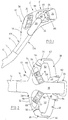
- the tiller head 10 shown in FIGS. 1 to 3 does not belong to the drawbar not shown shown truck or the like.
- the drawbar is indicated by the end of her stem 12. How recognizable an upward bend is made at 14 at the end of the stem.
- the stem-side also extends in this direction Section approximately rectangular in cross section 16 of the tiller head, which in a suitable manner with the Stem 12 is connected.
- the tiller head 10 has an extension of the handle side Section 16 has a horn 18 that is approximately in plan view Rectangular shape, but upwards in side view a hump shape, as indicated by the contour line 20.
- the horn is concave at the bottom in side view, as indicated by the contour line 22. This gives the horn 18 in the rear, facing the operator Part of an orientation that is approximately the axis of the stem 12 is parallel.
- Grasping the sides of the free end of the horn 18, above but exempt from the horn below is a box-shaped one Switch button 24 provided a body protection switch operated.
- the key 24 is stored in this way (not shown) that a touch from a variety of directions leads to a switch actuation.
- leg sections 34, 36 are connected, which are approximately extend parallel to the horn 18 towards the operator side and connected with rod-like handles 38, 40 are.
- the leg sections 34, 36 are on the horn 18 facing side in cross section approximately circular arc-shaped, while they are flattened on the outside like indicated at 42, 44 in Figures 2 and 3.
- the handles 38, 40 which lie on a circular arc line, whose center of circle lies on the side of the stem 12, extend in the direction of horn 18 up to throttle handles 46, 48 which are about an axis perpendicular to the horn the vertically running outside of the horn by a horizontal Axis are rotatably mounted.
- the axis of rotation corresponds approximately the axis of the handles 38, 40 near the Handles 46, 48.
- On the shape of the throttle handles 46, 48 will be discussed in more detail below.
- handle parts through the described parts 50, 52 are created for the fingers of one hand, which grips the handle 38 or 40 from behind and diagonally above.
- the handle openings 50, 52 have the greatest width in the plane of leg sections 34, 36 and handles 38, 40 approximately in the longitudinal center of support section 26, 28 or handle 38, 40, where they face the horn 18 back and forth towards the leg portions 34, 36 gradually arcuate narrow.
- the arch shape results from the curvature the handles 38, 40 and the corresponding concave curvature the support sections, as indicated by the contour lines 54, 56.
- a further curvature results from the contour line 58 or 60 of the travel switch handle 46 or 48 in Area of an index finger support surface 62 or 64 (on the latter will be discussed in more detail below).
- Troughs 66, 68 are formed in the support sections 26, 28. They extend at the foot of the horn 18 and from it Top side along the support sections 26, 28 in the direction Leg sections 34, 36. As can be seen in Fig. 1, have the troughs 66, 68 a slope towards the leg sections 34, 36. They also have a slope towards Handles 38, 40. Adjacent to the handle openings 50, 52, the troughs 66, 68 have an approximately straight edge 70 or 72, which has a substantially rectangular recess 74, 78 limited to the handle opening 50 and 52 respectively. In the Recess 70, 72 are immediately adjacent three switch buttons 80, 82 arranged in a row next to each other.
- the course of the series is the Switch buttons 80 and 82 approximately the course of the trough bottom adjusted, and the switch buttons 80, 82 are only slightly above the bottom of the trough 66 or 68.
- the Row of switch buttons 80, 82 therefore makes the slope in Direction of leg sections 34, 36 with.
- the switch buttons 80, 82 lie on an arc, the center of which is outside the trough 66, 68 lies with the axes of the keys 80, 82 intersect approximately in the center.
- leg portions 34, 36 and the handles 38, 40 lie in a plane that approximately coincides with the axis of the stem end portion 14 and forms an angle to the axis of the stem 12, which is directed downwards, approximately by an amount of 20 °.
- the angle that the handles 38, 40 form is about 160 °.
- the drive switch handles 46, 48 both a switch for regulating the driving speed of the conveyor not shown.
- the switch buttons 80, 82 are used for lifting and lowering and for honking, whereby how anyway recognizable, the functions on both sides of the Head 10 are designed redundantly. Of course it is also possible to "blind" one side of the tiller head to execute.
- the horn is preferably the farthest external switch button 80 or 82 actuated.
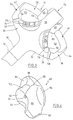
- the drive switch 48 is enlarged in FIGS shown. It has a disc shape on one side Section 84 on that of the corresponding flat surface facing the side of the horn 18. Back in A recessed grip 86 is formed towards the operator, which through approximately radially projecting sections 88 or 90 is limited. The projections 88, 90 close an angle of about 70 to 80 °. When capturing a Handle 40 the associated thumb of the hand gets into the Recessed grip 86 and can therefore handle 48 in both directions of rotation actuate. As is apparent from Figs. 4 and 6, is the axial extension of the projection 90 is significantly larger than that of the upper projection 88 so that the bottom of the Trough 86 gradually increases from lower projection 90 to upper 88 narrowed.
- the grip body 48 On the disc section 84 opposite side, the grip body 48 has a spherical recess 92 into which the spherical end the handles 38, 40 (see also FIG. 7) protrude, however with distance.
- the lower edge of the recess 92 faces on the one hand a recess 94 through which the assembly of the handle body 48 is made possible.
- a bore 91 is used to hold a bearing pin.
- the projection follows 88 on a flat surface 96 against which an index finger storage recess is located 98 connects.
- An inclined surface 100 extends in the direction from the upper flat surface 96 Recess 92 corresponding to the widening of the bottom the thumb recess 86.
- the finger recess extends 98 approximately over 180 ° of the handle body 48. It is in Cross section slightly concave and falls from the height of the disc section 84 continuously in the direction of the recess 92 from.
- the finger rest surface 98 (in FIGS. 2 and 3 position 62, 64) is shaped so that when gripping a handle, for example handle 40 from one hand the index finger itself place more or less curved on the surface 98 can.
- the bearing surface 98 therefore forms an extension of the handle 40 in the direction of the horn 18.
- the contact surface 98 shaped to be a continuation of the The contour of the handle 40 forms, as can be seen from FIGS. 1 to 3 results.
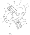
- the contours of the shown in Figures 1 to 3 Drawbar handle are such that when gripping a handle 38, 40 the switching buttons 80 and 82 with one hand one finger can be easily operated in a gripping position, without releasing the handle 38 or 40.
- the drive switch handle can also be operated by thumb 46 or 48 actuated in one or the other direction of rotation become. The actuation of the drive switch handle 46, 48 is ergonomically optimal even when the operator is comfortable turns away from the drawbar.
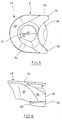
- the tiller head according to Figures 1 to 3 consists of two Parts, namely a lower part 104 and an upper part 106, which are described in more detail below with reference to FIGS. 7 and 8 should be. As far as in Figures 1 to 3 reproduced parts are shown, the same reference numerals used.
- the lower part is 104 designed as a supporting part with the horn lower part 18 ', the molded support section lower parts 26', 28 ', the leg portions 34, 36 and the handles 38, 40.
- Das Horn lower part 18 ' is over two itself in the direction of support sections 26 ', 28' triangular webs 27, 25 attached to the latter. Ice forms corresponding ones Holders for the travel switches 46, 48 and the body protection buttons 24.
- the handles 38, 40, the leg sections 34, 36 and also the support sections 26 ', 28' are in the Forming hollow in the plastic injection mold. This happens with the help of building up a corresponding gas pressure.
- the handles 38, 40 no annoying form seam and therefore do not need any special coating to make the handle manageable.
- a mounting lug 108 is formed with which the tiller head on the handle 12 of the drawbar not shown in the rest is attachable.
- a fastening bush is on the lower part of the tiller head 110 or 112 shaped for a fastening screw, not shown.
- the tiller head lower part 104 shown in FIG. 7 is made in one piece from plastic.
- the upper part 106 can be seen in FIG. It is bowl-like shaped and covered neck 108, lower part 18 ' of the horn. These parts are in Fig. 8 with 18 "and 108" designated. It also covers the lower part of the support section 26 ', 28'. The corresponding sections are shown in Fig. 8 labeled 26 "and 28". Lower part 104 and upper part 106 are screwed into the lugs 110, 112 by means of two Screws connected together.
- the upper part 106 is also made in one piece from plastic shaped.
Landscapes
- Engineering & Computer Science (AREA)
- Transportation (AREA)
- Mechanical Engineering (AREA)
- Chemical & Material Sciences (AREA)
- Combustion & Propulsion (AREA)
- Structural Engineering (AREA)
- Automation & Control Theory (AREA)
- Civil Engineering (AREA)
- Physics & Mathematics (AREA)
- Life Sciences & Earth Sciences (AREA)
- Geology (AREA)
- General Physics & Mathematics (AREA)
- Mechanical Control Devices (AREA)
Description

- Fig. 1
- zeigt perspektivisch die Seitenansicht eines Deichselkopfs nach der Erfindung.
- Fig. 2
- zeigt die Ansicht des Deichselkopfes nach Fig. 1 in Richtung Pfeil 2.
- Fig. 3
- zeigt die Ansicht des Deichselkopfes nach Fig. 1 in Richtung Pfeil 3.
- Fig. 4
- zeigt perspektivisch einen Fahrschaltergriff des Deichselkopfes nach den Figuren 1 bis 3.
- Fig. 5
- zeigt die Seitenansicht des Griffes nach Fig. 4
- Fig. 6
- zeigt die Ansicht des Griffes nach Fig. 5 in Richtung Pfeil 6.
- Fig. 7
- zeigt die Draufsicht auf das Unterteil des Deichselkopfes nach den Figuren 1 bis 3.
- Fig. 8
- zeigt die Draufsicht auf das Oberteil des Deichselkopfes nach den Figuren 1 bis 3.
- Fig. 9
- zeigt perspektivisch den Deichselkopf nach den Fig. 1 bis 3 bei der Betätigung von einer Hand.
Claims (25)
- Deichsel für kraftgetriebene Flurförderzeuge, mit einem Deichselstiel (12), einem am freien Ende des Deichselstiels (12) angeordneten Deichselkopf (10), bestehend aus einem in Verlängerung des Deichselstiels (12) angeordneten Horn (18), beidseits des Horns (18) sich annähernd quer zum Horn (18) erstreckenden stangenartigen Griffen (38, 40), einem am Horn schwenkbar gelagerten Fahrschaltergriff (46, 48), der eine vom Griff fortweisende Mulde (86) zur Betätigung mit dem Daumen aufweist, wobei die Griffe (38, 40) über an den äußeren Enden der Griffe (38, 40) angebundene und sich annähernd parallel zum Horn (18) erstreckende Schenkelabschnitte (34, 36) und über mit den Schenkelabschnitten (34, 36) verbundene Trägerabschnitte (26, 28) mit dem Horn (18) bzw. dem Stiel (12) verbunden sind und die Schenkel- und Trägerabschnitte einen Schutzbügel mit Grifföffnungen (50, 52) bilden, mindestens zwei Schalttasten (80, 82) auf jeder Seite des Horns (18), die in Flächen (66, 68) der Trägerabschnitte (26, 28) angebracht sind, die zur Vertikalen geneigt schräg in Richtung der Griffe (38, 40) hin abfallen, dadurch gekennzeichnet, daß die Flächen (66, 68) der Trägerabschnitte (26, 28) auch zur Seite hin abfallen, die Schalttasten (80, 82) in Reihe nebeneinander angeordnet sind und die Schalttastenreihen (80, 82) beidseits des Horns (18) im stumpfen Winkel angeordnet sind derart, daß sie in Richtung der Griffe (38, 40) konvergieren, um eine ergonomisch günstige Betätigung zu ermöglichen.
- Deichsel nach Anspruch 1, dadurch gekennzeichnet, daß rechteckige Tastknöpfe (80, 82) vorgesehen sind, die unmittelbar benachbart geringfügig aus der Fläche (66, 68) hervorstehen.
- Deichsel nach Anspruch 1 oder 2, dadurch gekennzeichnet, daß drei Schalttasten (80, 82) auf jeder Seite des Horns (18) angeordnet sind.
- Deichsel nach einem der Ansprüche 1 bis 3, dadurch gekennzeichnet, daß die Flächen von einer sich zwischen dem Horn (18) bzw. dem Stiel (12) und Schenkelabschnitt (34, 36) erstreckenden Mulde (66, 68) gebildet sind.
- Deichsel nach Anspruch 4, dadurch gekennzeichnet, daß die dem Griff (38, 40) zugewandte annähernd gerade Muldenkante (70, 72) zugleich die Grifföffnung (50, 52) auf seiten des Trägerabschnitts (26, 28) begrenzt und die Schalttasten (80,82) nahe der Muldenkante (70, 72) angeordnet sind.
- Deichsel nach einem der Ansprüche 1 bis 5, dadurch gekennzeichnet, daß die Achsen der Schalttasten auf einer Seite des Horns (18) nach oben konvergieren, vorzugsweise in einem Punkt, der dem Kreismittelpunkt für den Kreis entspricht, auf dem die Taste liegt bzw. den die Mulde beschreibt.
- Deichsel nach einem der Ansprüche 1 bis 6, dadurch gekennzeichnet, daß der obere Abschnitt (20) des Horns (18) über der aus Griff (38, 40) und Schenkelabschnitten (34, 36) gebildeten Ebene erhaben ist und die dem Horn (18) nächstgelegene Schalttaste (80, 82) annähernd an die Oberseite (20) des Horns (18) angrenzt.
- Deichsel nach einem der Ansprüche 1 bis 7, dadurch gekennzeichnet, daß die Trägerabschnitte (26, 28) als im Querschnitt gerundete Ansätze des Horns (18) gebildet sind, die sich vom Horn (18) fort stetig verjüngen.
- Deichsel nach Anspruch 8, dadurch gekennzeichnet, daß die Trägerabschnitte (26, 28) auf der der Grifföffnung (50, 52) gegenüberliegenden Seite konvex gebogen und im Querschnitt annähernd kreisförmig gerundet sind.
- Deichsel nach einem der Ansprüche 1 bis 8, dadurch gekennzeichnet, daß die Schenkelabschnitte (34, 36) zur Grifföffnung (50, 52) hin einen gerundeten Querschnitt aufweisen, der nach außen eine Abflachung (42, 44) aufweist.
- Deichsel nach einem der Ansprüche 1 bis 10, dadurch gekennzeichnet, daß die Trägerabschnitte (26, 28) zur Grifföffnung (50, 52) hin einen gerundeten Querschnitt aufweisen.
- Deichsel nach einem der Ansprüche 1 bis 11, dadurch gekennzeichnet, daß die außen liegenden Abschnitte der Trägerabschnitte (26,28) im stumpfen Winkel so zueinander angeordnet sind, daß sie in Richtung der Griffe (38, 40) divergieren.
- Deichsel nach einem der Ansprüche 1 bis 12, dadurch gekennzeichnet, daß die Griffe (38, 40) auf einer gebogenen Linie verlaufen, deren Kreismittelpunkt auf der dem Stiel (12) zugekehrten Seite liegt.
- Deichsel nach einem der Ansprüche 1 bis 13, dadurch gekennzeichnet, daß die Ebene aus Griff (38, 40) und Schenkelabschnitt (34, 36) in der Arbeitsstellung des Stiels (12) vom Griff (38, 40) fort schräg nach unten geneigt ist.
- Deichsel nach einem der Ansprüche 1 bis 14, dadurch gekennzeichnet, daß die Oberseite und die vom Bediener fortweisende Seite des Fahrschaltergriffes (46, 48) eine in Drehrichtung des Fahrschaltergriffes gekrümmte Ablagefläche (98) für den Zeigefinger der den Griff (38, 40) umfassenden Hand aufweist.
- Deichsel nach Anspruch 15, dadurch gekennzeichnet, daß die Ablagefläche (98) eine zum Horn (18) hin ansteigende Verlängerung des Griffes (38, 40) bildet.
- Deichsel nach einem der Ansprüche 1 bis 16, dadurch gekennzeichnet, daß der Fahrschaltergriff (46, 48) auf der dem Bediener zugekehrten Seite eine Daumenmulde (86) aufweist, deren nach oben weisender Bodenwandabschnitt schmaler als der nach unten weisende Bodenabschnitt ist und die seitliche Begrenzung des Fahrschaltergriffes (46, 48) im Bereich des schmalen Bodenwandabschnitts von einer Schrägfläche (100) gebildet ist mit einem Gefälle in Richtung Griff (38, 40).
- Deichsel nach einem der Ansprüche 1 bis 16, dadurch gekennzeichnet, daß das freie Ende des Griffes (38, 40) halbkugelförmig ist und in eine annähernd halbkugelförmige Ausnehmung des Fahrschaltergriffs (46, 48) hineinsteht.
- Deichsel nach einem der Ansprüche 1 bis 18, dadurch gekennzeichnet, daß ein Abschnitt des Horns (18) über die Fahrschaltergriffe (46, 48) vorsteht und in die Stirnseite des vorstehenden Abschnitts eine Schaltkappe (24) für einen Körperschutzschalter eingesetzt ist.
- Deichsel nach einem der Ansprüche 1 bis 19, dadurch gekennzeichnet, daß der Deichselkopf (10) aus einem über Schraubverbindungen verbindbaren Ober- und Unterteil (106, 104) zusammengesetzt ist, wobei das Unterteil (104) die Griffe (38, 40), die Schenkelabschnitte (34, 36), tragende Teile (26', 28') der Trägerabschnitte (26, 28) sowie Aufnahmen für die Fahrschalter (34, 36) und der Schutztaste (24) bzw. den tragenden Teil (18') des Horns (18) aufweist und das schalenartige Oberteil (106) die Oberseite des Horns (18) bildet sowie einen Teil (26'', 28") der Tragabschnitte (26, 28) einschließlich der die Schalttasten (80, 82) tragenden Fläche (66, 68).
- Deichsel nach Anspruch 20, dadurch gekennzeichnet, daß Unterteil (104) und/oder Oberteil (106) einteilig aus Kunststoff geformt sind.
- Deichsel nach Anspruch 20 oder 21, dadurch gekennzeichnet, daß Griffe (38, 40), Schenkelabschnitte (34, 36) und/oder tragende Teile (26', 28') der Trägerabschnitte hohl sind.
- Deichsel nach einem der Ansprüche 20 bis 22, dadurch gekennzeichnet, daß der tragende Teil (18') des Horns einen buchsenförmigen Ansatz (112) zur Aufnahme einer Verbindungsschraube aufweist.
- Deichsel nach einem der Ansprüche 20 bis 23, dadurch gekennzeichnet, daß der tragende Teil (18') des Horns über zwei beabstandete Stege (25, 27) an den tragenden Teilen (26', 28') der Trägerabschnitte angebunden ist.
- Deichsel nach einem der Ansprüche 1 bis 24, dadurch gekennzeichnet, daß die von den Schalttasten (80, 82) betätigten Schalter Proportionalschalter sind.
Applications Claiming Priority (2)
| Application Number | Priority Date | Filing Date | Title |
|---|---|---|---|
| DE19523921A DE19523921C2 (de) | 1995-06-30 | 1995-06-30 | Deichsel für kraftgetriebene Flurförderzeuge |
| DE19523921 | 1995-06-30 |
Publications (2)
| Publication Number | Publication Date |
|---|---|
| EP0751060A1 EP0751060A1 (de) | 1997-01-02 |
| EP0751060B1 true EP0751060B1 (de) | 1999-11-17 |
Family
ID=7765725
Family Applications (1)
| Application Number | Title | Priority Date | Filing Date |
|---|---|---|---|
| EP96109729A Expired - Lifetime EP0751060B1 (de) | 1995-06-30 | 1996-06-18 | Deichsel für kraftgetriebene Flurförderzeuge |
Country Status (2)
| Country | Link |
|---|---|
| EP (1) | EP0751060B1 (de) |
| DE (2) | DE19523921C2 (de) |
Families Citing this family (15)
| Publication number | Priority date | Publication date | Assignee | Title |
|---|---|---|---|---|
| DE19601694C2 (de) * | 1996-01-18 | 2001-11-08 | Still Wagner Gmbh & Co Kg | Deichsel für ein Flurförderzeug |
| SE521739C2 (sv) * | 1999-11-19 | 2003-12-02 | Bt Ind Ab | Förfarande för anpassining av reglage vid maskiner samt reglage för utövande av förfarandet |
| DE20008550U1 (de) | 2000-05-12 | 2000-08-10 | Jungheinrich Ag, 22047 Hamburg | Deichsel für kraftgetriebene Flurförderzeuge |
| DE20013656U1 (de) * | 2000-08-09 | 2001-01-11 | REMA Lipprandt GmbH & Co. KG, 53175 Bonn | Deichselkopf mit einem Fahrschalter für ein deichselgelenktes Flurförderzeug |
| DE10352695B4 (de) | 2003-11-12 | 2019-07-18 | Jungheinrich Aktiengesellschaft | Deichsel für kraftgetriebenes Flurförderzeug |
| DE102004042226A1 (de) * | 2004-09-01 | 2006-03-02 | Jungheinrich Ag | Deichsel für einen Mitgeh- und Mitfahrstapler |
| EP1867549B1 (de) | 2006-06-16 | 2013-07-24 | Atlet AB | Deichselkopf für ein kraftbetriebenes Flurförderzeug |
| DE102006031967A1 (de) * | 2006-07-11 | 2008-01-17 | Jungheinrich Aktiengesellschaft | Bedienanordnung in einem Flurförderzeug |
| DE102007047838A1 (de) | 2007-11-21 | 2009-05-28 | Zf Friedrichshafen Ag | Antrieb für ein Flurförderzeug |
| DE102008030554A1 (de) * | 2008-06-27 | 2009-12-31 | Still Wagner Gmbh | Bedienkonsole für ein Flurförderzeug |
| CN103149968B (zh) * | 2013-03-13 | 2015-04-29 | 浙江诺力机械股份有限公司 | 一种工业车辆的通用手柄 |
| DE102013006721A1 (de) * | 2013-04-19 | 2014-10-23 | Jungheinrich Aktiengesellschaft | Deichselgeführtes Flurförderzeug |
| DE102019101863A1 (de) | 2019-01-25 | 2020-07-30 | Jungheinrich Aktiengesellschaft | Bedienkopf für ein Flurförderzeug |
| CN112340657A (zh) * | 2020-11-04 | 2021-02-09 | 合肥德通电驱动系统有限公司 | 一种电动叉车手柄与操纵杆的连接安装结构 |
| WO2022222072A1 (en) | 2021-04-21 | 2022-10-27 | Crown Equipment Corporation | Tiller head |
Family Cites Families (5)
| Publication number | Priority date | Publication date | Assignee | Title |
|---|---|---|---|---|
| US4444284A (en) * | 1979-05-18 | 1984-04-24 | Big Joe Manufacturing Company | Control system |
| DE3840801A1 (de) * | 1988-12-01 | 1990-06-07 | Porsche Ag | Deichsel fuer von hand gefuehrte hubwagen und -lader |
| DE3840800A1 (de) * | 1988-12-01 | 1990-06-07 | Porsche Ag | Flurfoerderfahrzeug |
| US5245144A (en) * | 1991-10-25 | 1993-09-14 | Crown Equipment Corporation | Walk along hand grip switch control for pallet truck |
| DE4141270C2 (de) * | 1991-12-14 | 2001-06-07 | Philips Corp Intellectual Pty | Vorrichtung zur direkten und indirekten Betätigung insbesondere eines Kraftfahrzeugtürschlosses |
-
1995
- 1995-06-30 DE DE19523921A patent/DE19523921C2/de not_active Expired - Lifetime
-
1996
- 1996-06-18 EP EP96109729A patent/EP0751060B1/de not_active Expired - Lifetime
- 1996-06-18 DE DE59603656T patent/DE59603656D1/de not_active Expired - Lifetime
Also Published As
| Publication number | Publication date |
|---|---|
| DE59603656D1 (de) | 1999-12-23 |
| DE19523921A1 (de) | 1997-01-02 |
| DE19523921C2 (de) | 2001-11-29 |
| EP0751060A1 (de) | 1997-01-02 |
Similar Documents
| Publication | Publication Date | Title |
|---|---|---|
| EP0712062B1 (de) | Handbetätigte Stellvorrichtung für einen Bedienungsstand bzw. -sitz | |
| DE19523921C2 (de) | Deichsel für kraftgetriebene Flurförderzeuge | |
| DE3728373C2 (de) | Handbetätigbare Stellvorrichtung für Steuerventile | |
| DE10352695B4 (de) | Deichsel für kraftgetriebenes Flurförderzeug | |
| EP0750836B1 (de) | Heckenschere | |
| DE60225212T2 (de) | Nutzfahrzeug und Bedienfeld | |
| DE10104430A1 (de) | Verschiebbarer Sonnenschirmfuß | |
| EP3686152B1 (de) | Bedienkopf für ein flurförderzeug | |
| DE102019128145B4 (de) | Lenkrad | |
| EP1693334B1 (de) | Handbetätigte Bedienvorrichtung für einen Bedienplatz eines Flurförderzeugs | |
| DE102004042226A1 (de) | Deichsel für einen Mitgeh- und Mitfahrstapler | |
| EP1153815B1 (de) | Deichsel für kraftgetriebene Flurförderzeuge | |
| DE9417838U1 (de) | Handbetätigte Stellvorrichtung für einen Bedienungsstand bzw. -sitz | |
| EP1155939A2 (de) | Lenker für ein Flurförderzeug | |
| DE4206515C1 (de) | ||
| DE4006296C2 (de) | ||
| DE29511337U1 (de) | Deichsel für kraftgetriebene Flurförderzeuge | |
| DE4238414C2 (de) | Geh-geführter Rasenmäher | |
| EP2880503B1 (de) | Handbedienelement, insbesondere für eine baumaschine | |
| DE3418871A1 (de) | Bedienungsvorrichtung fuer eine baumaschine | |
| EP2628376B1 (de) | Landwirtschaftliches Arbeitsfahrzeug | |
| DE4413631C2 (de) | Deichsel eines Gabelhubwagens | |
| DE69422695T2 (de) | Fahrerkabine für Hebefahrzeuge | |
| EP0755666B1 (de) | Gehhilfe | |
| DE69617115T2 (de) | Tragbares Gartengerät mit einstellbarem Sicherheitsführungsgriff |
Legal Events
| Date | Code | Title | Description |
|---|---|---|---|
| PUAI | Public reference made under article 153(3) epc to a published international application that has entered the european phase |
Free format text: ORIGINAL CODE: 0009012 |
|
| AK | Designated contracting states |
Kind code of ref document: A1 Designated state(s): DE FR GB IT SE |
|
| 17P | Request for examination filed |
Effective date: 19961212 |
|
| 17Q | First examination report despatched |
Effective date: 19971125 |
|
| GRAG | Despatch of communication of intention to grant |
Free format text: ORIGINAL CODE: EPIDOS AGRA |
|
| GRAG | Despatch of communication of intention to grant |
Free format text: ORIGINAL CODE: EPIDOS AGRA |
|
| GRAH | Despatch of communication of intention to grant a patent |
Free format text: ORIGINAL CODE: EPIDOS IGRA |
|
| GRAH | Despatch of communication of intention to grant a patent |
Free format text: ORIGINAL CODE: EPIDOS IGRA |
|
| GRAA | (expected) grant |
Free format text: ORIGINAL CODE: 0009210 |
|
| AK | Designated contracting states |
Kind code of ref document: B1 Designated state(s): DE FR GB IT SE |
|
| GBT | Gb: translation of ep patent filed (gb section 77(6)(a)/1977) |
Effective date: 19991117 |
|
| REF | Corresponds to: |
Ref document number: 59603656 Country of ref document: DE Date of ref document: 19991223 |
|
| ITF | It: translation for a ep patent filed | ||
| ET | Fr: translation filed | ||
| PLBE | No opposition filed within time limit |
Free format text: ORIGINAL CODE: 0009261 |
|
| STAA | Information on the status of an ep patent application or granted ep patent |
Free format text: STATUS: NO OPPOSITION FILED WITHIN TIME LIMIT |
|
| 26N | No opposition filed | ||
| REG | Reference to a national code |
Ref country code: GB Ref legal event code: IF02 |
|
| REG | Reference to a national code |
Ref country code: FR Ref legal event code: PLFP Year of fee payment: 20 |
|
| PGFP | Annual fee paid to national office [announced via postgrant information from national office to epo] |
Ref country code: GB Payment date: 20150630 Year of fee payment: 20 |
|
| PGFP | Annual fee paid to national office [announced via postgrant information from national office to epo] |
Ref country code: DE Payment date: 20150831 Year of fee payment: 20 |
|
| PGFP | Annual fee paid to national office [announced via postgrant information from national office to epo] |
Ref country code: SE Payment date: 20150630 Year of fee payment: 20 Ref country code: FR Payment date: 20150630 Year of fee payment: 20 |
|
| PGFP | Annual fee paid to national office [announced via postgrant information from national office to epo] |
Ref country code: IT Payment date: 20150625 Year of fee payment: 20 |
|
| REG | Reference to a national code |
Ref country code: DE Ref legal event code: R071 Ref document number: 59603656 Country of ref document: DE |
|
| REG | Reference to a national code |
Ref country code: GB Ref legal event code: PE20 Expiry date: 20160617 |
|
| PG25 | Lapsed in a contracting state [announced via postgrant information from national office to epo] |
Ref country code: GB Free format text: LAPSE BECAUSE OF EXPIRATION OF PROTECTION Effective date: 20160617 |
|
| REG | Reference to a national code |
Ref country code: SE Ref legal event code: EUG |