EP0750657B9 - Vergasser - Google Patents
Vergasser Download PDFInfo
- Publication number
- EP0750657B9 EP0750657B9 EP95912813A EP95912813A EP0750657B9 EP 0750657 B9 EP0750657 B9 EP 0750657B9 EP 95912813 A EP95912813 A EP 95912813A EP 95912813 A EP95912813 A EP 95912813A EP 0750657 B9 EP0750657 B9 EP 0750657B9
- Authority
- EP
- European Patent Office
- Prior art keywords
- gas
- chamber
- reaction chamber
- gasifier
- conditioner
- Prior art date
- Legal status (The legal status is an assumption and is not a legal conclusion. Google has not performed a legal analysis and makes no representation as to the accuracy of the status listed.)
- Expired - Lifetime
Links
Images


Classifications
-
- C—CHEMISTRY; METALLURGY
- C10—PETROLEUM, GAS OR COKE INDUSTRIES; TECHNICAL GASES CONTAINING CARBON MONOXIDE; FUELS; LUBRICANTS; PEAT
- C10K—PURIFYING OR MODIFYING THE CHEMICAL COMPOSITION OF COMBUSTIBLE GASES CONTAINING CARBON MONOXIDE
- C10K3/00—Modifying the chemical composition of combustible gases containing carbon monoxide to produce an improved fuel, e.g. one of different calorific value, which may be free from carbon monoxide
- C10K3/06—Modifying the chemical composition of combustible gases containing carbon monoxide to produce an improved fuel, e.g. one of different calorific value, which may be free from carbon monoxide by mixing with gases
-
- C—CHEMISTRY; METALLURGY
- C10—PETROLEUM, GAS OR COKE INDUSTRIES; TECHNICAL GASES CONTAINING CARBON MONOXIDE; FUELS; LUBRICANTS; PEAT
- C10J—PRODUCTION OF PRODUCER GAS, WATER-GAS, SYNTHESIS GAS FROM SOLID CARBONACEOUS MATERIAL, OR MIXTURES CONTAINING THESE GASES; CARBURETTING AIR OR OTHER GASES
- C10J3/00—Production of combustible gases containing carbon monoxide from solid carbonaceous fuels
- C10J3/02—Fixed-bed gasification of lump fuel
- C10J3/20—Apparatus; Plants
- C10J3/34—Grates; Mechanical ash-removing devices
- C10J3/40—Movable grates
- C10J3/42—Rotary grates
-
- C—CHEMISTRY; METALLURGY
- C10—PETROLEUM, GAS OR COKE INDUSTRIES; TECHNICAL GASES CONTAINING CARBON MONOXIDE; FUELS; LUBRICANTS; PEAT
- C10J—PRODUCTION OF PRODUCER GAS, WATER-GAS, SYNTHESIS GAS FROM SOLID CARBONACEOUS MATERIAL, OR MIXTURES CONTAINING THESE GASES; CARBURETTING AIR OR OTHER GASES
- C10J3/00—Production of combustible gases containing carbon monoxide from solid carbonaceous fuels
- C10J3/46—Gasification of granular or pulverulent flues in suspension
- C10J3/48—Apparatus; Plants
- C10J3/482—Gasifiers with stationary fluidised bed
-
- C—CHEMISTRY; METALLURGY
- C10—PETROLEUM, GAS OR COKE INDUSTRIES; TECHNICAL GASES CONTAINING CARBON MONOXIDE; FUELS; LUBRICANTS; PEAT
- C10J—PRODUCTION OF PRODUCER GAS, WATER-GAS, SYNTHESIS GAS FROM SOLID CARBONACEOUS MATERIAL, OR MIXTURES CONTAINING THESE GASES; CARBURETTING AIR OR OTHER GASES
- C10J3/00—Production of combustible gases containing carbon monoxide from solid carbonaceous fuels
- C10J3/46—Gasification of granular or pulverulent flues in suspension
- C10J3/48—Apparatus; Plants
- C10J3/52—Ash-removing devices
- C10J3/523—Ash-removing devices for gasifiers with stationary fluidised bed
-
- C—CHEMISTRY; METALLURGY
- C10—PETROLEUM, GAS OR COKE INDUSTRIES; TECHNICAL GASES CONTAINING CARBON MONOXIDE; FUELS; LUBRICANTS; PEAT
- C10J—PRODUCTION OF PRODUCER GAS, WATER-GAS, SYNTHESIS GAS FROM SOLID CARBONACEOUS MATERIAL, OR MIXTURES CONTAINING THESE GASES; CARBURETTING AIR OR OTHER GASES
- C10J3/00—Production of combustible gases containing carbon monoxide from solid carbonaceous fuels
- C10J3/72—Other features
- C10J3/82—Gas withdrawal means
- C10J3/84—Gas withdrawal means with means for removing dust or tar from the gas
-
- C—CHEMISTRY; METALLURGY
- C10—PETROLEUM, GAS OR COKE INDUSTRIES; TECHNICAL GASES CONTAINING CARBON MONOXIDE; FUELS; LUBRICANTS; PEAT
- C10K—PURIFYING OR MODIFYING THE CHEMICAL COMPOSITION OF COMBUSTIBLE GASES CONTAINING CARBON MONOXIDE
- C10K1/00—Purifying combustible gases containing carbon monoxide
- C10K1/02—Dust removal
- C10K1/024—Dust removal by filtration
-
- C—CHEMISTRY; METALLURGY
- C10—PETROLEUM, GAS OR COKE INDUSTRIES; TECHNICAL GASES CONTAINING CARBON MONOXIDE; FUELS; LUBRICANTS; PEAT
- C10K—PURIFYING OR MODIFYING THE CHEMICAL COMPOSITION OF COMBUSTIBLE GASES CONTAINING CARBON MONOXIDE
- C10K3/00—Modifying the chemical composition of combustible gases containing carbon monoxide to produce an improved fuel, e.g. one of different calorific value, which may be free from carbon monoxide
- C10K3/001—Modifying the chemical composition of combustible gases containing carbon monoxide to produce an improved fuel, e.g. one of different calorific value, which may be free from carbon monoxide by thermal treatment
- C10K3/003—Reducing the tar content
- C10K3/008—Reducing the tar content by cracking
-
- C—CHEMISTRY; METALLURGY
- C10—PETROLEUM, GAS OR COKE INDUSTRIES; TECHNICAL GASES CONTAINING CARBON MONOXIDE; FUELS; LUBRICANTS; PEAT
- C10J—PRODUCTION OF PRODUCER GAS, WATER-GAS, SYNTHESIS GAS FROM SOLID CARBONACEOUS MATERIAL, OR MIXTURES CONTAINING THESE GASES; CARBURETTING AIR OR OTHER GASES
- C10J2300/00—Details of gasification processes
- C10J2300/09—Details of the feed, e.g. feeding of spent catalyst, inert gas or halogens
- C10J2300/0913—Carbonaceous raw material
- C10J2300/0916—Biomass
- C10J2300/092—Wood, cellulose
-
- C—CHEMISTRY; METALLURGY
- C10—PETROLEUM, GAS OR COKE INDUSTRIES; TECHNICAL GASES CONTAINING CARBON MONOXIDE; FUELS; LUBRICANTS; PEAT
- C10J—PRODUCTION OF PRODUCER GAS, WATER-GAS, SYNTHESIS GAS FROM SOLID CARBONACEOUS MATERIAL, OR MIXTURES CONTAINING THESE GASES; CARBURETTING AIR OR OTHER GASES
- C10J2300/00—Details of gasification processes
- C10J2300/09—Details of the feed, e.g. feeding of spent catalyst, inert gas or halogens
- C10J2300/0913—Carbonaceous raw material
- C10J2300/0916—Biomass
- C10J2300/0923—Sludge, e.g. from water treatment plant
-
- C—CHEMISTRY; METALLURGY
- C10—PETROLEUM, GAS OR COKE INDUSTRIES; TECHNICAL GASES CONTAINING CARBON MONOXIDE; FUELS; LUBRICANTS; PEAT
- C10J—PRODUCTION OF PRODUCER GAS, WATER-GAS, SYNTHESIS GAS FROM SOLID CARBONACEOUS MATERIAL, OR MIXTURES CONTAINING THESE GASES; CARBURETTING AIR OR OTHER GASES
- C10J2300/00—Details of gasification processes
- C10J2300/09—Details of the feed, e.g. feeding of spent catalyst, inert gas or halogens
- C10J2300/0913—Carbonaceous raw material
- C10J2300/093—Coal
-
- C—CHEMISTRY; METALLURGY
- C10—PETROLEUM, GAS OR COKE INDUSTRIES; TECHNICAL GASES CONTAINING CARBON MONOXIDE; FUELS; LUBRICANTS; PEAT
- C10J—PRODUCTION OF PRODUCER GAS, WATER-GAS, SYNTHESIS GAS FROM SOLID CARBONACEOUS MATERIAL, OR MIXTURES CONTAINING THESE GASES; CARBURETTING AIR OR OTHER GASES
- C10J2300/00—Details of gasification processes
- C10J2300/09—Details of the feed, e.g. feeding of spent catalyst, inert gas or halogens
- C10J2300/0913—Carbonaceous raw material
- C10J2300/0946—Waste, e.g. MSW, tires, glass, tar sand, peat, paper, lignite, oil shale
-
- C—CHEMISTRY; METALLURGY
- C10—PETROLEUM, GAS OR COKE INDUSTRIES; TECHNICAL GASES CONTAINING CARBON MONOXIDE; FUELS; LUBRICANTS; PEAT
- C10J—PRODUCTION OF PRODUCER GAS, WATER-GAS, SYNTHESIS GAS FROM SOLID CARBONACEOUS MATERIAL, OR MIXTURES CONTAINING THESE GASES; CARBURETTING AIR OR OTHER GASES
- C10J2300/00—Details of gasification processes
- C10J2300/16—Integration of gasification processes with another plant or parts within the plant
- C10J2300/1603—Integration of gasification processes with another plant or parts within the plant with gas treatment
- C10J2300/1606—Combustion processes
Definitions
- FR-A-885 815 discloses a gasifier.
- the present invention is directed to a gas conditioner, or secondary reactor vessel, for use with a gasification process. More particularly, the invention relates to a secondary reactor vessel for generating a relatively clean producer gas from a crude gas produced by a gasification process.
- Gasification processes particularly updraft gasification and other thermal processes, produce a crude gas that has a relatively low level of purity and includes toxic chemicals and other contaminants.
- a gas typically contains compounds such as carbon monoxide, hydrogen, methane, carbon dioxide, nitrogen and water vapor, and has an energy value of approximately 1,200 Kcal/m 3 to 1500 Kcal/m 3 .
- Pollutants such as tars, dust, and ash are also present, in relatively high concentrations, in these crude gases.
- the crude gas must normally be detared, filtered, purified and cooled before it is used in many energy producing applications.
- the crude gases may be passed through a gas conditioner or secondary reactor vessel where they are reacted at a relatively high temperature to crack and convert tars and hydrocarbons, thus yielding a more clean gas.
- gasifiers such as updraft gasifiers
- the present invention is directed to a gas conditioner or secondary reactor vessel for use in association with a gasification reactor, such as an updraft or fluidized bed gasifier.
- Gasification produces a crude, somewhat dirty gas containing carbon monoxide, hydrogen, methane, carbon dioxide, nitrogen and water vapor, as well as particulate pollutants such as tars, dust, and ash.
- a gas has an energy value of approximately 1,200 to 1500 Kcal/m 3 .
- the gas converter of the present invention receives the crude gas generated by gasification and cracks the entrained tars and hydrocarbons, converting them to hydrogen, methane and carbon monoxide, to yield a relatively clean producer gas which may then be channeled to an engine or gas turbine to produce electricity, or to a burner to generate heat.
- the gas conditioner comprises a reaction chamber for retaining a fuel supply and for containing a cracking reaction.
- the reaction chamber preferably is substantially cylindrical in shape, having boiler grade, or heat resistant, steel walls which preferably are at least partially lined, with a refractive material such as ceramic.
- An upp er portion of the chamber has an inlet conduit for receiving a crude gas from a gasification process and an inlet conduit for receiving process air. These conduits extend through the walls of the vessel and communicate with an internal reaction housing which mixes the air and crude gas and provides a primary reaction zone for the crude gas and process air.
- the internal reaction housing extends within the interior of the reaction chamber and is generally conical in shape, having its apex toward the top of the vessel and a bottom portion which is open to the bottom of the vessel.
- the housing preferably has a double-walled structure.
- the outer wall preferably is solid, while the inner wall features a number of perforations, at its bottom portion, which communicate with the interior of the housing.
- the perforations may be present in a single row at the bottom of the inner wall of the housing.
- the air inlet conduit communicates with the space defined by the inner and outer wall of the housing. The air is delivered to the interior of the chamber through the perforations in the inner wall.
- the raw gas inlet conduit communicates with and delivers a gas produced by a gasification process to the upper, interior portion of the housing which is defined by the inner wall of the housing.
- a baffle maybe utilized to disperse the entering gas and/or induce directional (e.g., rotational) flow in the gas.
- the process air and the crude gas become mixed and react.
- a fuel source preferably coke
- This chamber may also include a rotatable grate structure disposed at the bottom of the vessel upon which the fuel and ash may rest.
- a steam/air mixture, oxygen, or another burnable gas may be injected into the gasifier from the vicinity of the rotatable rate.
- a gas exit grate is housed within the wall of the chamber, spaced a predetermined distance from the midpoint of the reaction chamber.
- a discharge conduit communicates with the gas exit grate and the combustion chamber to withdraw producer gas from the vessel.
- the gas exit grate can also be incorporated, as a separate component, into gasifiers or reactors having designs other than the gasifier reactor described herein.
- the gas conditioner, or secondary reactor vessel, of the present invention prefer ably is used in connection with a gasifier system.
- the gas conditioner of the invent ion accepts a raw gas, having a relatively high tar, dust and ash content, produced by a gasification reaction and further converts the gas to yield a producer gas substantially free of tars, dust and ash.
- the raw gas from the gasifier 10 is fed into gas conditioner 12 where it is mixed with a process air, oxygen, or an air/steam mixture which is also drawn into conditioner 12.
- the resultant producer gas is withdrawn from conditioner 12 and is directed to a further processing station 14, such as an engine, turbine or burner (not shown).
- Gas conditioner 12 is generally cylindrical in shape and is constructed of boiler grade or heat resistant steel walls 16 which define a reaction chamber 18.
- the interior side walls 16 may preferably be lined with a refractive material (not shown), such as ceramic.
- a fuel feed mechanism 20 is disposed exterior to conditioner 12, preferably at a top portion thereof, and is adapted to selectively convey a fuel material 22, such as cc ke, to reaction chamber 18.
- a fuel material 22 such as cc ke
- Other fuel materials such as charcoal or other materials typically used in gas conditioners or gasifiers may be used instead of coke.
- the fuel takes the from of relatively small pellets of 0.5 to 5.0 cm in size.
- the reaction chamber 18 of gas conditioner 12 includes an internal reaction housing 24 which is disposed within a top portion of chamber 18.
- a rotating grate 26 is disposed at a bottom portion of chamber 18.
- Grate 26 also includes an air supply conduit 28 which communicates air, an air-stream mixture, or another gas to chamber 18 through grate 26.
- Cham ber 18 also includes a gas exit grate 30 which is disposed within chamber 18 and, preferably, is positioned 254 mm to 762 mm approximately (10 to 30 inches) below the bottom of the internal reaction housing 24.
- Gas exit grate 30 communicates with a discharge conduit 32, which extends through a sidewall 16 of the vessel for removing producer gas from chamber 18.
- the conditioner 12 further includes an ash fuel discharge device 33 for removing spent fuel from the vessel.
- the walls 16 of secondary reactor vessel 12 are of a thickness sufficient to adequately contain the reaction process which takes place within vessel 12.
- the side, top and bottom walls are 3.8 to 7.6 mm in thickness.
- the coating thickness preferably ranges from 10 to 20cm.
- the walls 16 may include cooling conduits (not shown).
- secondary reactor vessel 12 may vary depending upon the capacity desired for the apparatus. While the height and diameter of vessel may vary, the volume of chamber 18 may range from 50 to 3,000 m 3 per hour throughput. Preferably the height of chamber 18 ranges from 1.0 to 2.5 meters while the diameter of chamber 18 ranges from 0.5 to 3 meters.
- the chamber 18 is generally cylindrical in shape, however, other known configurations may be utilized for this chamber.
- the walls of chamber 18 may be substantially straight such that the diameter of chamber 18 is substantially uniform at all points along its height.
- the diameter of the chamber may increase uniformly from the top to the bottom of the chamber at an angle of 2° to 5°.
- the diameter of the chamber slightly increases from the top of the chamber to a point corresponding to the bottom of housing 24 at an angle of 2° to 5°. Thereafter, the diameter of chamber 18 may remain uniform. This configuration is preferred as it best enables fuel to gravitate from upper to lower portions of chamber 18.
- the internal reaction housing 24, illustrated in FIGURES 2 and 3, is a generally cone-shaped device which is suspended within a top portion of chamber 18 from raw gas inlet conduit 36 and air inlet conduit 34.
- Reaction housing 24 comprises inner 38 and outer 40 walls which are separated by a space 42 which may be about 10 to 50 mm.
- a primary reaction zone 44 is disposed interior of and is defined by interior wall 38.
- raw gas inlet conduit 36 traverses one side wall 16 of ves sel 12 and extends through a top portion of reaction chamber 18.
- Conduit 36 also traverses a top portion of walls 38, 40 of internal reaction housing 24 to enable conduit 36 to deposit raw gas within a top portion of primary reaction zone 44.
- a baffle 46 is disposed at a terminal portion of conduit 36 to impart directional flow, such as rotation, to the incoming gas and to provide for improved dispersion of the gas within zone 44.
- Air inlet conduit 34 likewise traverses one side wall 16 of vessel 12 and extends through a top portion of reaction chamber 18 to internal reaction housing 24.
- conduit 34 penetrates outer wall 40 of housing 24 to deposit air (or oxygen) into space 42 of the housing.
- the air may enter the primary reaction zone 44 through apertures 48 disposed in a bottom portion of inner wall 38.
- apertures 48 are disposed in single row within wall 38.
- the apertures 48 are generally circular or ovoid and are 2.5 to 5 cm in diameter.
- the apertures have angled nozzles to enable the air to circulate in the same direction as the raw gas.
- conduits 34 and 36 may include compensators 50, which are extension joints made, for example, of steel and are designed to allow internal reaction housing 24 to move vertically and horizontally.
- a vibrating mechanism 52 may be used in connection with internal reaction chamber 24.
- Vibrating mechanism 52 includes a motor 54 and a vibrating arm 57 which extends from the motor to a side portion of chamber 24.
- the vibrating mechanism may be selectively or continuously activated to prevent fuel, added through fuel feed mechanism 20, from adhering to chamber 24.
- housing 24 may be constructed of heat resistant steel or other such materials which are compatible with the reaction taking place within housing 24.
- inner wall may be constructed of heat resistant steel, while outer wall 40 is constructed of boiler grade steel.
- the steel material which makes up housing 24 is 1.5 to 2.0 cm in thickness.
- the dimensions of housing 24 may, of course, vary depending upon the overall size of the gas conditioner apparatus.
- the diameter of the housing at its base is 10 to 25 cm less than the interior diameter of the reaction chamber 18.
- the walls of housing 24 are sloped at an angle of 45 to 60 degrees.
- a gas exit grate assembly 30 is disposed within chamber 18 and extends about the circumference of chamber 18. Grate 30 is suspended from its top portion from wall 16 of chamber 18 and extends for a length of 0.25 to 0.4 meters. Preferably, the grate 30 is disposed at a location within chamber 18 just below the vertical mid-point of the chamber and adjacent to gas exit conduit 32.
- the gas exit grate 30 performs a type of filtering function as gas exiting the gas conditioner 12 passes through grate 30 before entering gas exit conduit 32. Some or all of the dust, ash or other particulate matter present in the gas will be prevented from exiting chamber 18 by grate 30.
- a plurality of spaced, adjacent rods 70 make up grate 30.
- a bracket 72 secured to wall 16 of chamber 18, supports a top portion of each of the rods 70 and allows the rods to extent downwardly from the point at which the rods are secured to bracket 72.
- Wall 16 and rods 70 define an annular space 74 which communicates with gas exit conduit 32.
- the rods 70 have a generally triangular cross section with each side of the rod having a width of 6 to 7 mm.
- Rods 70 are configured such that each rod is wider at its top portion and narrower at its bottom portion.
- a gap 76 which is defined by adjacent rods 70, is narrower at its top portion and wider at its bottom portion.
- the amount of taper for both rods 70 and gaps 76 ranges from a wider dimension of 6 mm to a narrower dimension of 4 mm.
- each rod has a length of about 300 mm as measured from its point of attachment at bracket 72 to its bottom end.
- Gas exit grate assembly 30 is useful as a component of gasifier or reactor systems that have different designs and constructions than gas conditioner 12 disclosed herein, Other components of gas conditioner 12 may also be used with other gasifier or reactor designs independent of the gas conditioner 12 described herein.
- the bottom of chamber 18 features a rotary grate 26 which serves to break-up large particles of spent ash and to facilitate removal of spent ash by discharge screw 58 of ash discharge device 33.
- a supply conduit 28 is disposed below and exterior to chamber 18 to communicate air, oxygen, or an air/steam mixture into chamber 18 through grate 26.
- a fuel material 22, preferably coke, is disposed within chamber 18, filling the chamber to a level corresponding approximately to the middle of housing 24.
- the fuel 22 may be added to chamber 18 through a fuel feed mechanism 20 mounted on a top portion of vessel 12.
- Fuel is transferred from a hopper or other storage means (not shown) to a rotary drum 53. As fuel fills one section of the drum 53, the drum rotates and deposits fuel within a top portion of vessel 12 through fuel passage 56.
- Spent ash is preferably withdrawn from vessel 12 through a discharge screw 58 disposed at the bottom of vessel 12.
- the fuel level may be controlled manually, or in a preferred embodiment by an automated means which adds additional fuel in response to a signal from a fuel level indicator.
- gas conditioner 12 of the present invention is designed to be used in conjunction with a gasifier 10.
- Gas conditioner 12 accepts a raw gas from the gasifier 10 and further purifies the gas by burning off and removing associated tars and ashes.
- gasifier may be used in connection with the gas conditioner of the invention.
- updraft gasifiers would more commonly be used with vessel 12 as such gasifiers tend to produce a raw gas having a greater content of tars and dust.
- the gasifier may be designed so as to bum virtually any known gasification fuel material, including those having a moisture content as high as 50-60% with an ash content as high as 30% as the gas conditioner of this invention has the capacity to eliminate a high level of impurities from a raw gas.
- Potential fuel materials which may be combusted within gasifier 10 include wood, sludge, trash, coal and others. Sludge-based materials are a preferred fuel source. Typically, as much as one to three tons of fuel material may be processed per hour with the present gas conditioner and a gasifier.
- the gas conditioner 12 receives raw gas from gasifier 10.
- the raw gas has a heat value of 1,200 to 1,500 Kcal/m 3 .
- the raw gas comprises about 5% carbon dioxide, 30% carbon monoxide, 13% hydrogen, 2% methane and about 50% nitrogen.
- the tar content of such gas is about 100 grams/m 3 and the dust content is about 200 grams/m 3 .
- the process air (or oxygen) enters conditioner 12 through conduit 34 and is directed into space 42 of internal reaction housing 24. Simultaneously, raw gas is fed into the primary reaction zone 44 of housing 24. As the air (or oxygen) enters the primary combustion zone 44 through apertures 48 it becomes mixed with the raw gas. At the same time, combustion of fuel 22 is occurring within chamber 18.
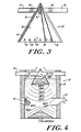
- the reaction process within chamber 18 results in temperatures within the reaction zone 44 being in the range of 1,200°-1,500°C. Temperatures within chamber 18 are highest adjacent the bottom of internal reaction housing 24. As illustrated in FIGURE 4, temperatures within chamber 18 at an area adjacent to internal reaction housing 24 are about 1200°C and gradually decrease to about 500°C at an area adjacent grate 30.
- a gas such as air or an air/steam mixture is added through rotary grate 26 and rises with additional air through the fuel 22 within chamber 18.
- Such a gas causes gasification of the coke fuel on the surface of grate 26, and the gas produced by this reaction also rises within chamber 18.
- the resultant producer gas traverses through chamber 18 to a position interior of gas exit grate 30. From this location the producer gas traverses grate 30 by passing through gaps 76 to annular space 74.
- the producer gas which enters annular space 74 is free of particulate matter, such as fuel, ash and dust, which is too large to pass through gaps 76.
- the producer gas entering annular space 74 is drawn out of the gas conditioner 12 through gas exit conduit 32.
- the exiting gas may then be transferred to a further processing station 14, such as a boiler or generator, where it may be utilized as an energy source.
- the exiting reaction gas typically has a heat value of about 1200 Kcal/m 3 .
- the heat value of this gas may be increased to about 2000 Kcal/m 3 by adding additional oxygen to the process air, or by replacing the process air with pure oxygen.
- the reaction gases comprise approximately 8.5% carbon dioxide, 22% carbon monoxide, 13% hydrogen, 2.5% methane and about 54% nitrogen.
Landscapes
- Chemical & Material Sciences (AREA)
- Engineering & Computer Science (AREA)
- Combustion & Propulsion (AREA)
- Oil, Petroleum & Natural Gas (AREA)
- Organic Chemistry (AREA)
- Chemical Kinetics & Catalysis (AREA)
- General Chemical & Material Sciences (AREA)
- Mechanical Engineering (AREA)
- Physics & Mathematics (AREA)
- Thermal Sciences (AREA)
- Industrial Gases (AREA)
- Iron Core Of Rotating Electric Machines (AREA)
- Sampling And Sample Adjustment (AREA)
- Processing Of Solid Wastes (AREA)
- Inorganic Insulating Materials (AREA)
- Diaphragms For Electromechanical Transducers (AREA)
- Liquid Developers In Electrophotography (AREA)
Claims (4)
- Vergaser, umfassend eine innere Reaktionskammer (18) mit Mitteln zum Halten eines Betts aus Brennstoff darin, und mit einer damit kommunizierenden Gasauslassleitung (32), wobei die Gasauslassleitung (32) in einer Seitenwand (16) der Reaktionskammer (18) über dem Betthaltemittel ausgebildet ist und wirksam ist, um ein Generatorgas aus dem Inneren der Reaktionskammer (18) zu entfernen; und
ein Filtrierrostmittel (30) zum Filtern eines Generatorgases, bevor das Generatorgas die innere Reaktionskammer (18) durch die Gasauslassleitung (32) verlässt, wobei das Filtrierrostmittel (30) eine Mehrzahl verteilter, benachbarter, vertikal ausgerichteter Stäbe (70) am Umfang um den Innenraum der inneren Reaktionskammer (18) so verteilt aufweist, dass ein Ringspalt (74) zwischen dem Filtrierrostmittel (30) und der Seitenwand (16) der Reaktionskammer (18) gebildet wird, wobei die Stäbe im wesentlichen vertikal sind, so dass mindestens einige der verteilten Stäbe an die Gasauslassleitung (32) angrenzen, und wobei die verteilten Stäbe (70) Spalte (76) zwischen sich begrenzen, durch die das Generatorgas zum Verlassen des Vergasers hindurchströmt, um das durch die verteilten Stäbe hindurchströmende Gas zu filtern. - Vergaser nach Anspruch 1, bei dem ein oberer Teil jedes Stabs (70) des Filtrierrostmittels (30) an einem ringförmigen Rand befestigt ist und von diesem herabhängt, der die Stäbe über einen an der Seitenwand (16) der Reaktionskammer (18) befestigten Träger (72) hält.
- Vergaser nach Anspruch 2, bei dem das Filtrierrostmittel (30) derart aufgebaut ist, dass der Raum zwischen benachbarten Stäben (70) schmaler an einem Ende angrenzend an den ringförmigen Rand ist und breiter an einem entgegengesetzten Ende ist.
- Vergaser nach Anspruch 2, bei dem das Filtrierrostmittel (30) derart aufgebaut ist, dass jeder Stab (70) breiter an dem an dem ringförmigen Rand befestigten Ende ist und schmaler an dem entgegensetzten Ende desselben ist.
Applications Claiming Priority (3)
| Application Number | Priority Date | Filing Date | Title |
|---|---|---|---|
| US21468294A | 1994-03-16 | 1994-03-16 | |
| US214682 | 1994-03-16 | ||
| PCT/US1995/002919 WO1995025151A1 (en) | 1994-03-16 | 1995-03-08 | Gas conditioner apparatus and method |
Publications (4)
| Publication Number | Publication Date |
|---|---|
| EP0750657A1 EP0750657A1 (de) | 1997-01-02 |
| EP0750657A4 EP0750657A4 (de) | 1997-11-05 |
| EP0750657B1 EP0750657B1 (de) | 2004-01-21 |
| EP0750657B9 true EP0750657B9 (de) | 2004-10-27 |
Family
ID=22800040
Family Applications (1)
| Application Number | Title | Priority Date | Filing Date |
|---|---|---|---|
| EP95912813A Expired - Lifetime EP0750657B9 (de) | 1994-03-16 | 1995-03-08 | Vergasser |
Country Status (5)
| Country | Link |
|---|---|
| US (2) | US5571294A (de) |
| EP (1) | EP0750657B9 (de) |
| AT (1) | ATE258216T1 (de) |
| DE (1) | DE69532468T8 (de) |
| WO (1) | WO1995025151A1 (de) |
Families Citing this family (8)
| Publication number | Priority date | Publication date | Assignee | Title |
|---|---|---|---|---|
| DE69613811D1 (de) * | 1996-04-09 | 2001-08-16 | Ansaldo Ricerche S R L | Methode und System zur Erzeugung und Verwendung von Brenngasen, insbesondere Gasen hergestellt aus Biomassen und Abfall |
| DE10030778C2 (de) * | 2000-06-23 | 2002-11-14 | Nachhaltige Stoffnutzung Mbh G | Verfahren und Vorrichtung zur Erzeugung eines Brenngases aus Biomassen |
| DE10127138C2 (de) * | 2000-06-23 | 2003-12-24 | Nachhaltige Stoffnutzung Mbh G | Verfahren und Vorrichtung zur Erzeugung eines Brenngases aus Biomassen |
| DE102013112995B4 (de) * | 2013-11-25 | 2019-10-31 | L'Air Liquide, Société Anonyme pour l'Etude et l'Exploitation des Procédés Georges Claude | Verfahren zum Aufheizen eines Brennstoffbettes in einem Festbettdruckvergasungsreaktor |
| US9790443B2 (en) * | 2014-09-09 | 2017-10-17 | Suzhou GreenGen Tech Energy Inc. | Vertical pyrolysis reactor with precise control |
| CN104403693B (zh) * | 2014-12-11 | 2017-01-04 | 赛鼎工程有限公司 | 一种碎煤加压气化炉 |
| CN104449856B (zh) * | 2014-12-11 | 2017-01-04 | 赛鼎工程有限公司 | 一种节能型碎煤加压干排灰气化炉 |
| FR3043080B1 (fr) * | 2015-11-04 | 2021-01-08 | Haffner Energy | Procede de production de gaz synthetique hypergaz |
Family Cites Families (35)
| Publication number | Priority date | Publication date | Assignee | Title |
|---|---|---|---|---|
| US1175844A (en) * | 1915-10-26 | 1916-03-14 | Bruno Versen | Gas-producer. |
| US1499437A (en) * | 1921-04-25 | 1924-07-01 | Adams Ralph | Spark arrester |
| FR885815A (fr) * | 1942-05-11 | 1943-09-27 | Procédé de gazéification de combustibles goudronneux et humides et installation pour sa mise en oeuvre | |
| US2455561A (en) * | 1946-06-28 | 1948-12-07 | Kellogg M W Co | Reducing disengaging height in fluidized powder systems |
| US2476760A (en) * | 1946-08-08 | 1949-07-19 | Ohlsson Olof Axel | Process and apparatus for the operation of gas producers |
| US2634198A (en) * | 1947-06-11 | 1953-04-07 | Hydrocarbon Research Inc | Coal carbonization and gasification |
| US2689786A (en) * | 1949-01-20 | 1954-09-21 | Hubmann Otto | Process for the gasification of solid fuels |
| US2805188A (en) * | 1952-10-23 | 1957-09-03 | Koppers Co Inc | Process for producing synthesis gas and coke |
| US2775513A (en) * | 1955-01-27 | 1956-12-25 | Frank J Termany | Gasifying apparatus |
| NL103920C (de) * | 1958-03-07 | 1900-01-01 | ||
| US3543700A (en) * | 1969-07-07 | 1970-12-01 | Environmental Control Products | Air purifying incinerator apparatus |
| US3658482A (en) * | 1970-09-08 | 1972-04-25 | College Research Corp | Afterburner |
| AR205469A1 (es) * | 1974-07-04 | 1976-05-07 | Kiener Karl | Procedimiento y dispositivo de obtencion de gas combustible |
| US4142867A (en) * | 1974-07-04 | 1979-03-06 | Karl Kiener | Apparatus for the production of combustible gas |
| US3951082A (en) * | 1975-04-22 | 1976-04-20 | The United States Of America As Represented By The United States Energy Research And Development Administration | Countercurrent flow afterburner |
| DE2700044A1 (de) * | 1977-01-03 | 1978-07-06 | Didier Eng | Verfahren zur verhinderung von kondensation beim transport heissen koksofenrohgases zur verwendungsstelle |
| DE2736687A1 (de) * | 1977-08-16 | 1979-03-01 | Metallgesellschaft Ag | Verfahren und vorrichtung zur vergasung koerniger kohle unter erhoehtem druck |
| US4145979A (en) * | 1978-01-23 | 1979-03-27 | Envirotech Corporation | Afterburner assembly |
| DE2822862C2 (de) * | 1978-05-26 | 1984-01-05 | Ruhrchemie Ag, 4200 Oberhausen | Verfahren zur Gewinnung wasserstoff- und kohlenmonoxidhaltiger Gasgemische durch Vergasung kohlenstoffhaltiger, aschebildender Brennstoffe |
| DE2947222A1 (de) * | 1979-11-23 | 1981-05-27 | Carbon Gas Technologie GmbH, 4030 Ratingen | Verfahren zur vergasung von festem, staubfoermig bis stueckigem kohlestoffhaltigem material |
| US4334484A (en) * | 1980-01-18 | 1982-06-15 | University Of Kentucky Research Foundation | Biomass gasifier combustor |
| US4453474A (en) * | 1980-09-29 | 1984-06-12 | Sterling Drug, Inc. | Method for controlling temperatures in the afterburner and combustion hearths of a multiple hearth furnace |
| US4456455A (en) * | 1981-03-23 | 1984-06-26 | Fluidised Bed Combustion (Proprietary) Limited | Two stage coal gasification plant |
| AU9139882A (en) * | 1982-05-24 | 1983-12-08 | Krw Energy Systems Inc. | Fluid cooled carryover barrier for gasification system |
| DE3317977A1 (de) * | 1983-05-18 | 1984-11-22 | Pka Pyrolyse Kraftanlagen Gmbh, 7080 Aalen | Gaswandler |
| US4504291A (en) * | 1983-06-29 | 1985-03-12 | Mobil Oil Corporation | Dropout boot for power recovery train |
| DE3335544A1 (de) * | 1983-09-28 | 1985-04-04 | Herwig 1000 Berlin Michel-Kim | Reaktorvorrichtung zur erzeugung von generatorgas aus brennbaren abfallprodukten |
| AT401420B (de) * | 1983-10-17 | 1996-09-25 | Berthiller Franz | Einrichtung zur verfeuerung von biomasse |
| US4520760A (en) * | 1984-04-23 | 1985-06-04 | Combustion Engineering, Inc. | Heat exchanger outlet arrangement |
| DE3611429A1 (de) * | 1985-02-15 | 1986-11-06 | SKF Steel Engineering AB, Hofors | Verfahren zur abfallzersetzung |
| US4764184A (en) * | 1986-01-10 | 1988-08-16 | Sasol Operations (Proprietary) Limited | Apparatus for the gasification of coal |
| DE3633210A1 (de) * | 1986-09-30 | 1988-03-31 | Siemens Ag | Gaswandler fuer kohlenwasserstoffhaltige schwelgase |
| US5277880A (en) * | 1988-05-11 | 1994-01-11 | Uop | Catalyst regeneration apparatus with radial flow distribution |
| DE3824233A1 (de) * | 1988-07-16 | 1990-01-18 | Krupp Koppers Gmbh | Anlage fuer die erzeugung eines produktgases aus einem feinteiligen kohlenstofftraeger |
| US5139535A (en) * | 1991-05-08 | 1992-08-18 | The United States Of America As Represented By The United States Department Of Energy | Two-stage fixed-bed gasifier with selectable middle gas off-take point |
-
1995
- 1995-03-08 AT AT95912813T patent/ATE258216T1/de active
- 1995-03-08 EP EP95912813A patent/EP0750657B9/de not_active Expired - Lifetime
- 1995-03-08 DE DE69532468T patent/DE69532468T8/de active Active
- 1995-03-08 WO PCT/US1995/002919 patent/WO1995025151A1/en active IP Right Grant
- 1995-06-02 US US08/458,980 patent/US5571294A/en not_active Expired - Lifetime
-
1996
- 1996-02-22 US US08/605,640 patent/US5580361A/en not_active Expired - Lifetime
Also Published As
| Publication number | Publication date |
|---|---|
| EP0750657B1 (de) | 2004-01-21 |
| US5571294A (en) | 1996-11-05 |
| DE69532468D1 (de) | 2004-02-26 |
| WO1995025151A1 (en) | 1995-09-21 |
| EP0750657A1 (de) | 1997-01-02 |
| DE69532468T8 (de) | 2006-03-02 |
| US5580361A (en) | 1996-12-03 |
| DE69532468T2 (de) | 2004-10-07 |
| EP0750657A4 (de) | 1997-11-05 |
| ATE258216T1 (de) | 2004-02-15 |
Similar Documents
| Publication | Publication Date | Title |
|---|---|---|
| US4498909A (en) | Process for the gasification of fuels | |
| US3927996A (en) | Coal injection system | |
| US5026403A (en) | Three stage process for producing producer gas from combustible waste products | |
| EP1348011B1 (de) | Multifacetten-vergaser und verwandte verfahren | |
| US5922092A (en) | Bottom feed - updraft gasification system | |
| US20180085761A1 (en) | Using a Cyclone Separator and a Fixed-Bed Gasifier to Generate a Product Gas from Carbon-Containing Input Substances | |
| EP2952557B1 (de) | Reinigungsvorrichtung und -verfahren mit mikrowelleninduziertem plasma für produktgas | |
| CA1052102A (en) | Slag bath generator adapted to operate under pressure | |
| EP0750657B9 (de) | Vergasser | |
| EP1129154B1 (de) | Verfahren zur vergasung von kohlenstoffhaltigen treibstoffen in einem festbettvergaser | |
| US4165970A (en) | Process and apparatus for gasifying granular coal under superatmospheric pressure | |
| US4088455A (en) | Process and apparatus for a pressure gasification of fuels mainly in lump form | |
| JPS61207491A (ja) | 燃料ガス化装置 | |
| JPS63193989A (ja) | 燃料のガス化法 | |
| CA2184998C (en) | Gas conditioner apparatus and method | |
| KR19990028458A (ko) | 연료 가스 생성 방법 및 장치 | |
| GB2106130A (en) | Gasification | |
| WO2014207755A1 (en) | Zero effluent discharge biomass gasification | |
| RU2073061C1 (ru) | Способ получения полукокса из бурых и каменных углей | |
| EP3050941B1 (de) | Verfahren und reaktor für vergasung von organischen materialen | |
| CA3172343C (en) | Waste processing system | |
| GB2259521A (en) | Moving bed coal gasifier | |
| EP4209710A1 (de) | Wirbelbetteinheit | |
| EP0051482A1 (de) | Erzeugung von Generatorgas | |
| SU1104148A1 (ru) | Установка дл газификации пылевидного топлива |
Legal Events
| Date | Code | Title | Description |
|---|---|---|---|
| PUAI | Public reference made under article 153(3) epc to a published international application that has entered the european phase |
Free format text: ORIGINAL CODE: 0009012 |
|
| 17P | Request for examination filed |
Effective date: 19961016 |
|
| AK | Designated contracting states |
Kind code of ref document: A1 Designated state(s): AT BE CH DE DK ES FR GB GR IE IT LI LU MC NL PT SE |
|
| A4 | Supplementary search report drawn up and despatched |
Effective date: 19970922 |
|
| AK | Designated contracting states |
Kind code of ref document: A4 Designated state(s): AT BE CH DE DK ES FR GB GR IE IT LI LU MC NL PT SE |
|
| 17Q | First examination report despatched |
Effective date: 19990217 |
|
| GRAH | Despatch of communication of intention to grant a patent |
Free format text: ORIGINAL CODE: EPIDOS IGRA |
|
| RTI1 | Title (correction) |
Free format text: GASIFIER |
|
| RTI1 | Title (correction) |
Free format text: GASIFIER |
|
| RTI1 | Title (correction) |
Free format text: GASIFIER |
|
| GRAS | Grant fee paid |
Free format text: ORIGINAL CODE: EPIDOSNIGR3 |
|
| GRAA | (expected) grant |
Free format text: ORIGINAL CODE: 0009210 |
|
| AK | Designated contracting states |
Kind code of ref document: B1 Designated state(s): AT BE CH DE DK ES FR GB GR IE IT LI LU MC NL PT SE |
|
| PG25 | Lapsed in a contracting state [announced via postgrant information from national office to epo] |
Ref country code: NL Free format text: LAPSE BECAUSE OF FAILURE TO SUBMIT A TRANSLATION OF THE DESCRIPTION OR TO PAY THE FEE WITHIN THE PRESCRIBED TIME-LIMIT Effective date: 20040121 Ref country code: FR Free format text: LAPSE BECAUSE OF FAILURE TO SUBMIT A TRANSLATION OF THE DESCRIPTION OR TO PAY THE FEE WITHIN THE PRESCRIBED TIME-LIMIT Effective date: 20040121 |
|
| REG | Reference to a national code |
Ref country code: GB Ref legal event code: FG4D |
|
| REG | Reference to a national code |
Ref country code: CH Ref legal event code: EP |
|
| REG | Reference to a national code |
Ref country code: IE Ref legal event code: FG4D |
|
| REF | Corresponds to: |
Ref document number: 69532468 Country of ref document: DE Date of ref document: 20040226 Kind code of ref document: P |
|
| PG25 | Lapsed in a contracting state [announced via postgrant information from national office to epo] |
Ref country code: LU Free format text: LAPSE BECAUSE OF NON-PAYMENT OF DUE FEES Effective date: 20040308 Ref country code: IE Free format text: LAPSE BECAUSE OF NON-PAYMENT OF DUE FEES Effective date: 20040308 |
|
| PG25 | Lapsed in a contracting state [announced via postgrant information from national office to epo] |
Ref country code: MC Free format text: LAPSE BECAUSE OF NON-PAYMENT OF DUE FEES Effective date: 20040331 |
|
| PG25 | Lapsed in a contracting state [announced via postgrant information from national office to epo] |
Ref country code: SE Free format text: LAPSE BECAUSE OF FAILURE TO SUBMIT A TRANSLATION OF THE DESCRIPTION OR TO PAY THE FEE WITHIN THE PRESCRIBED TIME-LIMIT Effective date: 20040421 Ref country code: GR Free format text: LAPSE BECAUSE OF FAILURE TO SUBMIT A TRANSLATION OF THE DESCRIPTION OR TO PAY THE FEE WITHIN THE PRESCRIBED TIME-LIMIT Effective date: 20040421 Ref country code: GB Free format text: LAPSE BECAUSE OF NON-PAYMENT OF DUE FEES Effective date: 20040421 Ref country code: DK Free format text: LAPSE BECAUSE OF FAILURE TO SUBMIT A TRANSLATION OF THE DESCRIPTION OR TO PAY THE FEE WITHIN THE PRESCRIBED TIME-LIMIT Effective date: 20040421 |
|
| PG25 | Lapsed in a contracting state [announced via postgrant information from national office to epo] |
Ref country code: ES Free format text: LAPSE BECAUSE OF FAILURE TO SUBMIT A TRANSLATION OF THE DESCRIPTION OR TO PAY THE FEE WITHIN THE PRESCRIBED TIME-LIMIT Effective date: 20040502 |
|
| NLV1 | Nl: lapsed or annulled due to failure to fulfill the requirements of art. 29p and 29m of the patents act | ||
| REG | Reference to a national code |
Ref country code: CH Ref legal event code: NV Representative=s name: BRAUN & PARTNER PATENT-, MARKEN-, RECHTSANWAELTE |
|
| PLBE | No opposition filed within time limit |
Free format text: ORIGINAL CODE: 0009261 |
|
| STAA | Information on the status of an ep patent application or granted ep patent |
Free format text: STATUS: NO OPPOSITION FILED WITHIN TIME LIMIT |
|
| GBPC | Gb: european patent ceased through non-payment of renewal fee |
Effective date: 20040421 |
|
| 26N | No opposition filed |
Effective date: 20041022 |
|
| EN | Fr: translation not filed | ||
| EN | Fr: translation not filed | ||
| REG | Reference to a national code |
Ref country code: IE Ref legal event code: MM4A |
|
| REG | Reference to a national code |
Ref country code: FR Ref legal event code: ERR Free format text: BOPI DE PUBLICATION N: 05/03 PAGES: 237 PARTIE DU BULLETIN CONCERNEE: BREVETS EUROPEENS DONT LA TRADUCTION N'A PAS ETE REMISE A I'INPI IL Y A LIEU DE SUPPRIMER: LA MENTION DE LA NON REMISE. |
|
| PG25 | Lapsed in a contracting state [announced via postgrant information from national office to epo] |
Ref country code: PT Free format text: LAPSE BECAUSE OF NON-PAYMENT OF DUE FEES Effective date: 20040621 |
|
| PGFP | Annual fee paid to national office [announced via postgrant information from national office to epo] |
Ref country code: CH Payment date: 20140327 Year of fee payment: 20 |
|
| PGFP | Annual fee paid to national office [announced via postgrant information from national office to epo] |
Ref country code: IT Payment date: 20140324 Year of fee payment: 20 Ref country code: AT Payment date: 20140305 Year of fee payment: 20 |
|
| PGFP | Annual fee paid to national office [announced via postgrant information from national office to epo] |
Ref country code: BE Payment date: 20140328 Year of fee payment: 20 |
|
| PGFP | Annual fee paid to national office [announced via postgrant information from national office to epo] |
Ref country code: DE Payment date: 20140327 Year of fee payment: 20 |
|
| REG | Reference to a national code |
Ref country code: DE Ref legal event code: R071 Ref document number: 69532468 Country of ref document: DE |
|
| REG | Reference to a national code |
Ref country code: CH Ref legal event code: PL |
|
| REG | Reference to a national code |
Ref country code: AT Ref legal event code: MK07 Ref document number: 258216 Country of ref document: AT Kind code of ref document: T Effective date: 20150308 |