EP0750556B1 - Betätigungsbaugruppe für eine kraftfahrzeug-bremsanlage - Google Patents
Betätigungsbaugruppe für eine kraftfahrzeug-bremsanlage Download PDFInfo
- Publication number
- EP0750556B1 EP0750556B1 EP95912166A EP95912166A EP0750556B1 EP 0750556 B1 EP0750556 B1 EP 0750556B1 EP 95912166 A EP95912166 A EP 95912166A EP 95912166 A EP95912166 A EP 95912166A EP 0750556 B1 EP0750556 B1 EP 0750556B1
- Authority
- EP
- European Patent Office
- Prior art keywords
- housing
- power
- piston
- output member
- master cylinder
- Prior art date
- Legal status (The legal status is an assumption and is not a legal conclusion. Google has not performed a legal analysis and makes no representation as to the accuracy of the status listed.)
- Expired - Lifetime
Links
- 239000013013 elastic material Substances 0.000 claims description 2
- 230000000284 resting effect Effects 0.000 abstract 1
- 238000005452 bending Methods 0.000 description 4
- 125000006850 spacer group Chemical group 0.000 description 2
- 230000003321 amplification Effects 0.000 description 1
- 230000005540 biological transmission Effects 0.000 description 1
- 238000004519 manufacturing process Methods 0.000 description 1
- 238000012986 modification Methods 0.000 description 1
- 230000004048 modification Effects 0.000 description 1
- 238000003199 nucleic acid amplification method Methods 0.000 description 1
- 238000005192 partition Methods 0.000 description 1
- 238000007789 sealing Methods 0.000 description 1
Images


Classifications
-
- B—PERFORMING OPERATIONS; TRANSPORTING
- B60—VEHICLES IN GENERAL
- B60T—VEHICLE BRAKE CONTROL SYSTEMS OR PARTS THEREOF; BRAKE CONTROL SYSTEMS OR PARTS THEREOF, IN GENERAL; ARRANGEMENT OF BRAKING ELEMENTS ON VEHICLES IN GENERAL; PORTABLE DEVICES FOR PREVENTING UNWANTED MOVEMENT OF VEHICLES; VEHICLE MODIFICATIONS TO FACILITATE COOLING OF BRAKES
- B60T13/00—Transmitting braking action from initiating means to ultimate brake actuator with power assistance or drive; Brake systems incorporating such transmitting means, e.g. air-pressure brake systems
- B60T13/10—Transmitting braking action from initiating means to ultimate brake actuator with power assistance or drive; Brake systems incorporating such transmitting means, e.g. air-pressure brake systems with fluid assistance, drive, or release
- B60T13/24—Transmitting braking action from initiating means to ultimate brake actuator with power assistance or drive; Brake systems incorporating such transmitting means, e.g. air-pressure brake systems with fluid assistance, drive, or release the fluid being gaseous
- B60T13/46—Vacuum systems
- B60T13/52—Vacuum systems indirect, i.e. vacuum booster units
- B60T13/565—Vacuum systems indirect, i.e. vacuum booster units characterised by being associated with master cylinders, e.g. integrally formed
Definitions
- the invention relates to an actuation assembly according to the preamble of claim 1.
- the force output member extends freely through a central bore in a cap part, which is attached to an annular front attachment of a retaining disk is attached, which belongs to the axially movable partition of the booster.
- the delivery piston of the force intensifier is held in a recess in the said disk which receives it.
- the invention has for its object to provide in an actuation assembly for a motor vehicle brake system with a pneumatic brake booster and a hydraulic master brake cylinder that the intended for the transmission and amplification of axial forces components even if they are not exactly aligned with each other from the beginning , can only be loaded with low transverse forces and bending moments.
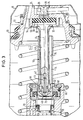
- the assembly shown in FIGS. 1 and 2 includes a pneumatic brake booster of essentially conventional design, which is essentially rotationally symmetrical with respect to an axis A.
- the brake booster 10 has an amplifier housing 12 comprising a front housing part 14 and a rear housing part 16, which are held together by axially parallel tie rods 18 and enclose a space which is separated by an axially movable intermediate wall 20 into a front and a rear chamber B or C is divided.
- the front chamber B is constantly connected to a vacuum source, for example the suction line of a gasoline engine; the rear chamber C can be connected to the front chamber B or to the surrounding atmosphere, optionally also to a compressed air source, by means of a control valve.
- the control valve is also of a known type; its most important components are a valve housing 22 with a central body 24, on which a radially outer, annular valve seat is formed, a valve piston 26, on which a radially inner annular valve seat is formed, and a sealing body 28, which cooperates with the two valve seats.
- a rod-shaped force input member 30 is inserted into the valve housing 22 from behind.
- a mechanical force intensifier 32 is arranged in front of the valve piston 26 and has an input piston 34 of smaller diameter, an output piston 36 of larger diameter and a reaction disk 38 arranged between these two pistons and made of rubber-elastic material.
- the mechanical force translator 32 increases the input force in the ratio of the areas of the output piston 36 and the input piston 34 that are in contact with the reaction disk.
- the delivery piston 36 interacts with a rod-shaped force delivery member 40, at the rear end of which it is formed in one piece in the example shown.
- the force output member 40 further has an axial bore 42, in which a spacer ring 46 and a spherically rounded end piece 48 are fastened with a notch pin 44 or a similar fastening means.
- the force output member 40 is almost completely enclosed by a sleeve 50 at a radial distance.
- the sleeve 50 ends at the front with a spherical head piece 52 and at the rear with a cup-shaped foot 54, which protrudes forward annular approach 56 of the central body 24 of the valve housing 22 encloses without play. 1 to 3, the foot 54 forms an interference fit with the annular extension 56 enclosed by it.
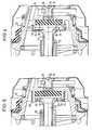
- the projection 56 has an annular groove 58 on its outside, in which radially inward deformations of the foot 54 engage. According to FIG.
- axially parallel projections 58 ' are formed on the ring-shaped extension 56, each of which extends forward through a hole in the cup-shaped foot 54 and the front of which is caulked.
- the annular groove 58 and the projections 58 ' form additional safeguards against the cup-shaped foot 54 slipping axially from the ring-shaped projection 56.
- the press-fit of the cup-shaped foot 54 on the ring-shaped projection 56 is so tight that the two cannot separate from one another anyway .
- a master brake cylinder 60 coaxially with the brake booster 10, a master brake cylinder 60 is arranged, which has a master cylinder housing 62 with a flange 64.
- the flange 64 is attached to the tie rods 18 and is held in the position shown, with nuts, not shown, in which the master cylinder housing 62 extends axially into the booster housing 12.
- the rear end region of the master cylinder housing 62 which is arranged within the booster housing 12, contains a firmly and tightly installed end ring 66 with a central bore, which forms an axial guide 68.
- a primary piston 70 In front of the end ring 66, a primary piston 70 is guided in the master cylinder housing 62 and has a pan-shaped support 72 on its rear side.
- the front end piece 48 of the force output member 40 engages in this.
- the spacer ring 46 is dimensioned so that the front end piece 48 lies in the illustrated rest position of the primary piston 70 without play in its cup-shaped support 72 and is thereby also centered.
- the primary piston 70 has a tubular extension 74 which extends axially backwards from the pan-shaped support 72 and only shortly before the cup-shaped foot 54 and the Power converter 32 ends.
- the extension 74 has a circular cylindrical inner surface 76 on which the spherical head piece 52 of the sleeve 50 is guided.
- the head piece 52 is arranged only a short distance behind the pan-shaped support 72 within the space enclosed by the guide 68 and is normally the only area of the sleeve 50 which touches the tubular extension 74 of the primary piston 70.
- An annular space normally remains between the main part of the sleeve 50 and the inner surface 76 of the extension 74, as can be seen above all from FIGS. 2, 4 and 5.
- the master brake cylinder 60 is provided for a two-circuit brake system. Accordingly, a secondary piston 80, which delimits a secondary pressure chamber 82, is arranged in the master cylinder housing 62 in front of the primary piston 70, separated from it by a primary pressure chamber 78.
- a tandem arrangement is not one of the necessary requirements for the described design of the sleeve 50 and the components that interact directly with it.
- the primary piston 70 is therefore to be understood as the piston which is intended to convert a force exerted on it by the force output member 40 into a hydraulic pressure.
Landscapes
- Engineering & Computer Science (AREA)
- Transportation (AREA)
- Mechanical Engineering (AREA)
- Braking Systems And Boosters (AREA)
Abstract
Description
- Die Erfindung betrifft eine Betätigungsbaugruppe nach dem Oberbegriff des Anspruchs 1.
- Bei einer bekannten Betätigungsbaugruppe dieser Gattung (DE 33 18 272 A1) ragt die am Ventilgehäuse starr befestigte Hülse nur geringfügig in den rohrförmigen Fortsatz des Primärkolbens hinein. Das Kopfstück der Hülse hat somit einen erheblichen axialen Abstand von der am Primärkolben ausgebildeten Abstützung für das Kraftabgabeglied. Achsfluchtungsfehler, die bei Herstellung und Zusammenbau der im Oberbegriff des Anspruchs 1 genannten Teile einer Betätigungsbaugruppe nicht ganz zu vermeiden sind, führen bei dieser bekannten Anordnung dazu, daß der rohrförmige Fortsatz des Primärkolbens mit Biegemomenten belastet wird. Dies ist zwar insofern unschädlich als der rohrförmige Fortsatz genügend kräftig bemessen werden kann, um selbst erheblichen Biegemomenten standzuhalten. Es ist aber bisher unbeachtet geblieben, daß ein Achsfluchtungsfehler zwischen dem Kraftabgabeglied und dem Primärkolben des Hauptbremszylinders in Verbindung mit solchen Biegemomenten bewirken kann, daß der Primärkolben erheblich mit Querkräften belastet und infolgedessen in seiner Axialbeweglichkeit behindert und vorzeitig verschlissen wird.
- Bei einer anderen bekannten Betätigungsbaugruppe (DE 32 22 929 A1) mit einem pneumatischen Bremskraftverstärker, an dessen Gehäuse von vorne her ein Hauptbremszylinder angebaut ist, erstreckt sich das Kraftabgabeglied frei beweglich durch eine Mittel-bohrung eines Kappenteils, das auf einen ringförmigen vorderen Ansatz einer Haltescheibe aufgesetzt ist, welche zur axialbeweglichen Zwischenwand des Kraftverstärkers gehört. Durch dieses Kappenteil ist der Abgabekolben des Kraftübersetzers in einer ihn aufnehmenden Aussparung der genannten Scheibe festgehalten.
- Der Erfindung liegt die Aufgabe zugrunde, bei einer Betätigungsbaugruppe für eine Kraftfahrzeug-Bremsanlage mit einem pneumatischen Bremskraftverstärker und einem hydraulischen Hauptbremszylinder dafür zu sorgen, daß die zur Übertragung und Verstärkung von Axialkräften vorgesehenen Bauteile auch dann, wenn sie von Anfang an nicht ganz genau miteinander fluchten, nur mit geringen Querkräften und Biegemomenten belastet werden.
- Die Aufgabe ist erfindungsgemäß mit den Merkmalen des Anspruchs 1 gelöst. Eine Vorteilhafte Weiterbildung ergibt sich aus dem Unteranspruch.
- Ausführungsbeispiele der Erfindung werden im Folgenden anhand schematischer Zeichnungen mit weiteren Einzelheiten erläutert. Es zeigen:
- Fig. 1
- eine erfindungsgemäße Betätigungsbaugruppe in einem axialen Schnitt,
- Fig. 2
- einen vergrößerten Ausschnitt aus Fig. 1,
- Fig. 3
- einen entsprechenden Ausschnitt bei einem maximalen Achsfluchtungsfehler,
- Fig. 4
- eine gegenüber Fig. 2 abgewandelte Ausführungsform und
- Fig. 5
- eine weitere Abwandlung von Fig. 2.
- Zu der in Fig. 1 und 2 dargestellten Baugruppe gehört ein pneumatischer Bremskraftverstärker von im wesentlichen üblicher Bauweise, der in Bezug auf eine Achse A im wesentlichen rotationssymmetrisch ist. Der Bremskraftverstärker 10 hat ein Verstärkergehäuse 12 aus einem vorderen Gehäuseteil 14 und einem hinteren Gehäuseteil 16, die durch achsparallele Zuganker 18 zusammengehalten sind und einen Raum umschließen, der durch eine axial bewegliche Zwischenwand 20 in eine vordere und eine hintere Kammer B bzw. C unterteilt ist. Die vordere Kammer B ist im Betrieb ständig an eine Unterdruckquelle, beispielsweise Saugleitung eines Ottomotors, angeschlossen; die hintere Kammer C läßt sich durch ein Steuerventil wahlweise mit der vorderen Kammer B oder mit der umgebenden Atmosphäre, gegebenenfalls auch mit einer Druckluftquelle, verbinden.
- Das Steuerventil ist von ebenfalls bekannter Bauart; seine wichtigsten Bauteile sind ein Ventilgehäuse 22 mit einem zentralen Körper 24, an dem ein radial äußerer, ringförmiger Ventilsitz ausgebildet ist, ein Ventilkolben 26, an dem ein radial innerer ringförmiger Ventilsitz ausgebildet ist, und ein Dichtkörper 28, der mit den beiden Ventilsitzen zusammenwirkt. Zum Betätigen des Ventilkolbens 26 ist von hinten her in das Ventilgehäuse 22 ein stangenförmiges Krafteingabeglied 30 eingeführt. Vor dem Ventilkolben 26 ist ein mechanischer Kraftübersetzer 32 angeordnet, der einen Eingabekolben 34 kleineren Durchmessers, einen Abgabekolben 36 größeren Durchmessers und eine zischen diesen beiden Kolben angeordnete Reaktionsscheibe 38 aus gummielastichen Material aufweist. Beim Betätigen des Krafteingabegliedes 30 vergrößert der mechanische Kraftübersetzer 32 die Eingangskraft im Verhältnis der an der Reaktionsscheibe anliegenden Flächen des Abgabekolbens 36 und des Eingabekolbens 34.
- Der Abgabekolben 36 wirkt mit einem stangenförmigen Kraftabgabeglied 40 zusammen, an dessen hinterem Ende er im dargestellten Beispiel einstückig ausgebildet ist. Das Kraftabgabeglied 40 hat weiter vorne eine axiale Bohrung 42, in der mit einem Kerbstift 44 oder einem ähnlichen Befestigungsmittel ein Distanzring 46 und ein vorne sphärisch abgerundetes Endstück 48 befestigt sind.
- Das Kraftabgabeglied 40 ist nahezu auf seiner gesamten Länge von einer Hülse 50 in radialem Abstand umschlossen. Die Hülse 50 endet vorne mit einem sphärischen Kopfstück 52 und hinten mit einem topfförmigen Fuß 54, der einen nach vorne ragenden ringfförmigen Ansatz 56 des zentralen Körpers 24 des Ventilgehäuses 22 spielfrei umschließt. Gemäß Fig. 1 bis 3 bildet der Fuß 54 mit dem von ihm umschlossenen ringförmigen Ansatz 56 einen Preßsitz. Gemäß Fig. 4 weist der Ansatz 56 an seiner Außenseite eine Ringnut 58 auf, in die radial nach innen gerichtete Verformungen des Fußes 54 eingreifen. Gemäß Fig. 5 sind am ringförmigen Ansatz 56 achsparallele Vorsprünge 58' ausgebildet, die sich durch je ein Loch im topfförmigen Fuß 54 hindurch nach vorne erstrecken und dessen Vorderseite verstemmt sind. Die Ringnut 58 und die Vorsprünge 58' bilden zusätzliche Sicherungen gegen ein axiales Abrutschen des topfförmigen Fußes 54 vom ringförmigen Ansatz 56. Im allgemeinen ist jedoch der Preßsitz des topfförmigen Fußes 54 auf dem ringförmigen Ansatz 56 so fest, daß beide sich ohnehin nicht voneinander trennen können.
- Im Prinzip gleichachsig mit dem Bremskraftverstärker 10 ist ein Hauptbremszylinder 60 angeordnet, der ein Hauptzylindergehäuse 62 mit einem Flansch 64 aufweist. Der Flansch 64 ist auf die Zuganker 18 aufgesteckt und mit nicht dargestellten Muttern in der abgebildeten Stellung festgehalten, in der sich das Hauptzylindergehäuse 62 axial in das Verstärkergehäuse 12 hineinerstreckt. Der innerhalb des Verstärkergehäuses 12 angeordnete hintere Endbereich des Hauptzylindergehäuses 62 enthält einen fest und dicht eingebauten Abschlußring 66 mit einer zentralen Bohrung, die eine axiale Führung 68 bildet. Vor dem Abschlußring 66 ist im Hauptzylindergehäuse 62 ein Primärkolben 70 geführt, der an seiner Rückseite eine pfannenförmige Abstützung 72 aufweist. In diese greift das vordere Endstück 48 des Kraftabgabegliedes 40 ein. Der Distanzring 46 ist so bemessen, daß das vordere Endstück 48 in der abgebildeten Ruhestellung des Primärkolbens 70 spielfrei in dessen pfannenförmiger Abstützung 72 liegt und dadurch auch zentriert ist.
- Der Primärkolben 70 hat einen rohrförmigen Fortsatz 74, der sich von der pfannenförmigen Abstützung 72 aus axial nach hinten erstreckt und erst kurz vor dem topfförmigen Fuß 54 und dem Kraftübersetzer 32 endet. Der Fortsatz 74 hat eine kreiszylindrische Innenfläche 76, an der das sphärische Kopfstück 52 der Hülse 50 geführt ist. Das Kopfstück 52 ist in einem nur geringen Abstand hinter der pfannenförmigen Abstützung 72 innerhalb des von der Führung 68 umschlossenen Raumes angeordnet und ist normalerweise der einzige Bereich der Hülse 50, der den rohrförmigen Fortsatz 74 des Primärkolbens 70 berührt. Zwischen dem Hauptteil der Hülse 50 und der Innenfläche 76 des Fortsatzes 74 bleibt also, wie vorallem aus Fig. 2, 4 und 5 ersichtlich ist, normalerweise ein Ringraum frei. Wenn jedoch zwischen dem Kraftabgabeglied 40 und dem Primärkolben 70 ein Achsfluchtungsfehler auftritt, wird dieser gemäß Fig. 3 auf eine unschädliche Größe dadurch begrenzt, daß die Hülse 50 gegen den hinteren Randbereich des rohrförmigen Fortsatzes 54 stößt und dadurch zusätzlich geführt wird.
- Gemäß Fig. 1 ist der Hauptbremszylinder 60 für eine Zweikreis-Bremsanlage vorgesehen. Dementsprechend ist im Hauptzylindergehäuse 62 vor den Primärkolben 70, durch einen Primärdruckraum 78 von ihm getrennt, ein Sekundärkolben 80 angeordnet, der einen Sekundärdruckraum 82 begrenzt. Eine solche Tandemanordnung gehört jedoch nicht zu den notwendigen Voraussetzungen für die beschriebene Gestaltung der Hülse 50 und der mit ihr unmittelbar zusammenwirkenden Bauteile. Der Primärkolben 70 ist deshalb unabhängig von der Anzahl vorgesehener Bremskreise als derjenige Kolben zu verstehen, der dazu vorgesehen ist, eine vom Kraftabgabeglied 40 auf ihn ausgeübte Kraft in einen hydraulischen Druck umzusetzen.
Claims (2)
- Betätigungsbaugruppe für eine Kraftfahrzeug-Bremsanlage, bei der ein pneumatischer Bremskraftverstärker (10) und ein hydraulischer Hauptbremszylinder (60) längs einer gemeinsamen Achse (A) hintereinander angeordnet sind, mit- einem Verstärkergehäuse (12), in dem eine axial bewegliche Zwischenwand (20) zwei an Quellen unterschiedlichen Druckes anschließbare Kammern (B,C) voneinander trennt,- einem Ventilgehäuse (22), das mit der Zwischenwand (20) zu gemeinsamer Axialbewegung verbunden ist,- einem Krafteingabeglied (30) und einem Kraftabgabeglied (40), die in Bezug auf das Verstärkergehäuse (12) und das Ventilgehäuse (22) axial verschiebbar sind,- einem mechanischen Kraftübersetzer (32), der zwischen Krafteingabeglied (30) und Kraftabgabeglied (40) angeordnet ist und einen Eingabekolben (34) kleineren Durchmessers, einen Abgabekolben (36) größeren Durchmessers sowie eine zwischen diesen Kolben angeordnete gummielastische Reaktionsscheibe (38) aufweist,- einem Hauptzylindergehäuse (62), das am Verstärkergehäuse (12) befestigt ist und eine dem Kraftübersetzer (32) zugewandte Führung (68) aufweist,- einem Primärkolben (70), der im Hauptzylindergehäuse (62) geführt ist und eine Abstützung (72) für das Kraftabgabeglied (40) sowie einen sich in Richtung zum Kraftübersetzer (32) erstreckenden rohrförmigen Fortsatz (74) aufweist, der in der genannten Führung (68) geführt ist, und- einer Hülse (50), die am Ventilgehäuse (22) starr befestigt ist, einen Abschnitt des Kraftabgabegliedes (40) mit radialem Abstand umschließt, und ein Kopfstück (52) aufweist, das an einer Innenfläche (76) des Fortsatzes (74) geführt ist,
dadurch gekennzeichnet, daß die Hülse (50) sich bis in die Nähe der am Primärkolben (70) ausgebildeten Abstützung (72) erstreckt und das Kopfstück (52) innerhalb der von der genannten Führung (68) umschlossenen Raumes angeordnet ist. - Betätigungsbaugruppe nach Anspruch 1,
dadurch gekennzeichnet, daß die Hülse (50) einen topfförmigen Fuß (54) aufweist, der einen ringförmigen Ansatz (56) des Ventilgehäuses (22) spielfrei umschließt und auch den Kraftübersetzer (32) umschließt.
Applications Claiming Priority (3)
| Application Number | Priority Date | Filing Date | Title |
|---|---|---|---|
| DE4408993A DE4408993C2 (de) | 1994-03-16 | 1994-03-16 | Betätigungsbaugruppe für eine Kraftfahrzeug-Bremsanlage |
| DE4408993 | 1994-03-16 | ||
| PCT/EP1995/000704 WO1995025029A1 (de) | 1994-03-16 | 1995-02-27 | Betätigungsbaugruppe für eine kraftfahrzeug-bremsanlage |
Publications (2)
| Publication Number | Publication Date |
|---|---|
| EP0750556A1 EP0750556A1 (de) | 1997-01-02 |
| EP0750556B1 true EP0750556B1 (de) | 1997-12-29 |
Family
ID=6512983
Family Applications (1)
| Application Number | Title | Priority Date | Filing Date |
|---|---|---|---|
| EP95912166A Expired - Lifetime EP0750556B1 (de) | 1994-03-16 | 1995-02-27 | Betätigungsbaugruppe für eine kraftfahrzeug-bremsanlage |
Country Status (6)
| Country | Link |
|---|---|
| US (1) | US5732556A (de) |
| EP (1) | EP0750556B1 (de) |
| JP (1) | JPH09510162A (de) |
| DE (2) | DE4408993C2 (de) |
| ES (1) | ES2111397T3 (de) |
| WO (1) | WO1995025029A1 (de) |
Families Citing this family (7)
| Publication number | Priority date | Publication date | Assignee | Title |
|---|---|---|---|---|
| US5802852A (en) * | 1997-06-20 | 1998-09-08 | Robert Bosch Technology Corporation | Brake booster with an integrated master cylinder |
| US5964140A (en) * | 1997-08-26 | 1999-10-12 | Itt Manufacturing Enterprises, Inc. | Tandem master cylinder piston protection with centering guide |
| FR2784642B1 (fr) * | 1998-10-20 | 2000-12-15 | Bosch Sist De Frenado Sl | Maitre-cylindre a reaction hydraulique et a effort d'entree accru |
| DE29905522U1 (de) * | 1999-03-25 | 2000-09-21 | Lucas Industries Plc, Solihull, West Midlands | Steuerventilhalteelement |
| DE19937769B4 (de) | 1999-08-10 | 2005-06-09 | Lucas Industries P.L.C., Solihull | Pneumatischer Bremskraftverstärker und Verfahren zu dessen Herstellung |
| DE102006033534A1 (de) * | 2006-04-25 | 2007-10-31 | Continental Teves Ag & Co. Ohg | Pneumatischer Bremskraftverstärker |
| EP2357339A1 (de) | 2010-02-12 | 2011-08-17 | Siemens Aktiengesellschaft | Verfahren zur Bestimmung einer Verbrennerausgangstemperatur und Verfahren zur Steuerung einer Gasturbine |
Family Cites Families (13)
| Publication number | Priority date | Publication date | Assignee | Title |
|---|---|---|---|---|
| US3172335A (en) * | 1961-08-07 | 1965-03-09 | Gen Motors Corp | Power brake booster |
| DE2918914A1 (de) * | 1979-05-10 | 1980-12-11 | Teves Gmbh Alfred | Bremskraftverstaerker |
| GB2077868A (en) * | 1980-05-22 | 1981-12-23 | Lucas Industries Ltd | Boosted Master Cylinder Assemblies |
| JPS57204257U (de) * | 1981-06-20 | 1982-12-25 | ||
| DE3318272A1 (de) * | 1983-05-19 | 1984-11-22 | FAG Kugelfischer Georg Schäfer KGaA, 8720 Schweinfurt | Fuehrungselement in einem vakuum-bremskraftverstaerker |
| DE3402962A1 (de) * | 1984-01-28 | 1985-08-01 | Alfred Teves Gmbh, 6000 Frankfurt | Vakuumbremskraftverstaerker |
| DE3709172A1 (de) * | 1987-03-20 | 1988-09-29 | Teves Gmbh Alfred | Vakuumbremskraftverstaerker fuer kraftfahrzeuge und verfahren zu dessen herstellung |
| DE3740691A1 (de) * | 1987-12-01 | 1989-06-15 | Teves Gmbh Alfred | Vakuumbremskraftverstaerker fuer kraftfahrzeuge |
| DE4202820C2 (de) * | 1992-01-31 | 1996-09-05 | Lucas Ind Plc | Betätigungseinheit für Kraftfahrzeugbremsen |
| FR2693965B1 (fr) * | 1992-07-22 | 1994-09-23 | Bendix Europ Services Tech | Dispositif pneumatique de retenue en côte. |
| BR9307075A (pt) * | 1992-09-30 | 1999-08-24 | Alliedsignal Europ Services | Dispositivo refor-ador de freio com rea-Æo hidr ulica retardada |
| FR2696142B1 (fr) * | 1992-09-30 | 1994-12-30 | Alliedsignal Europ Services | Dispositif de freinage assisté à réaction hydraulique et saut réglable. |
| JP3214772B2 (ja) * | 1994-01-25 | 2001-10-02 | 日信工業株式会社 | 負圧ブースタにおけるブースタシェルの補強構造 |
-
1994
- 1994-03-16 DE DE4408993A patent/DE4408993C2/de not_active Expired - Fee Related
-
1995
- 1995-02-27 WO PCT/EP1995/000704 patent/WO1995025029A1/de not_active Ceased
- 1995-02-27 EP EP95912166A patent/EP0750556B1/de not_active Expired - Lifetime
- 1995-02-27 JP JP7523797A patent/JPH09510162A/ja active Pending
- 1995-02-27 DE DE59501172T patent/DE59501172D1/de not_active Expired - Fee Related
- 1995-02-27 ES ES95912166T patent/ES2111397T3/es not_active Expired - Lifetime
-
1996
- 1996-08-01 US US08/691,117 patent/US5732556A/en not_active Expired - Fee Related
Also Published As
| Publication number | Publication date |
|---|---|
| JPH09510162A (ja) | 1997-10-14 |
| ES2111397T3 (es) | 1998-03-01 |
| EP0750556A1 (de) | 1997-01-02 |
| WO1995025029A1 (de) | 1995-09-21 |
| DE59501172D1 (de) | 1998-02-05 |
| DE4408993C2 (de) | 1997-05-07 |
| US5732556A (en) | 1998-03-31 |
| DE4408993A1 (de) | 1995-09-21 |
Similar Documents
| Publication | Publication Date | Title |
|---|---|---|
| DE3046965A1 (de) | Pneumatischer servo-booster | |
| EP0318681B1 (de) | Vakuumbremskraftverstärker für Kraftfahrzeuge | |
| DE602004003938T2 (de) | Servomotor mit verringertem totgang und solch einen servomotor umfassendes bremssystem | |
| DE60204090T2 (de) | Bremskraftverstärker | |
| EP0257360B1 (de) | Bremskraftverstärker-Hauptzylinderbaugruppe | |
| DE19841150B4 (de) | Bremskraftverstärker mit Panikbremsfunktion | |
| EP0166985B1 (de) | Pneumatischer Kraftverstärker, insbesondere für Bremsanlagen von Kraftfahrzeugen | |
| DE4408993C2 (de) | Betätigungsbaugruppe für eine Kraftfahrzeug-Bremsanlage | |
| WO1999002385A1 (de) | Sensoranordnung für einen bremskraftverstärker und damit ausgerüsteter bremskraftverstärker | |
| DE102009037232A1 (de) | Pneumatischer Bremskraftverstärker | |
| EP0322524B1 (de) | Tandembremskraftverstärker für Kraftfahrzeuge | |
| DE3018270C2 (de) | ||
| DE1655969C3 (de) | Bremskraftverstärker für Kraftfahrzeuge | |
| DE69312173T2 (de) | Pneumatische Kraftverstärker für Fahrzeugbremsanlagen | |
| DE19916579A1 (de) | Pneumatischer Bremskraftverstärker mit veränderlichem Kraftübersetzungsverhältnis | |
| EP0681539B1 (de) | Unterdruckbremskraftverstärker für kraftfahrzeuge | |
| DE69709116T2 (de) | Bremskraftverstärker mit hydraulischer reaktion und mit grösserer sicherheit | |
| DE102011003510A1 (de) | Bremskraftverstärker für eine Kraftfahrzeugbremsanlage mit regenerativer Bremskrafterzeugung | |
| DE19539601B4 (de) | Unterdruckbremskraftverstärker für Kraftfahrzeuge | |
| DE69516014T2 (de) | Pneumatischer bremskraftverstärker | |
| DE3232664A1 (de) | Kraftverstaerker, insbesondere zum betaetigen der bremsen von fahrzeugen | |
| EP2379387B1 (de) | Pneumatischer bremskraftverstärker für eine fahrzeugbremsanlage | |
| DE19756225C2 (de) | Vakuumbremskraftverstärker | |
| DE10244916A1 (de) | Federspeicherbremszylinder mit selbstzentrierender Druckplatten-Rückstellfeder | |
| DE4440657A1 (de) | Betätigungsbaugruppe für eine Kraftfahrzeug-Bremsanlage |
Legal Events
| Date | Code | Title | Description |
|---|---|---|---|
| PUAI | Public reference made under article 153(3) epc to a published international application that has entered the european phase |
Free format text: ORIGINAL CODE: 0009012 |
|
| 17P | Request for examination filed |
Effective date: 19960902 |
|
| AK | Designated contracting states |
Kind code of ref document: A1 Designated state(s): DE ES FR GB IT |
|
| GRAG | Despatch of communication of intention to grant |
Free format text: ORIGINAL CODE: EPIDOS AGRA |
|
| 17Q | First examination report despatched |
Effective date: 19970312 |
|
| GRAG | Despatch of communication of intention to grant |
Free format text: ORIGINAL CODE: EPIDOS AGRA |
|
| GRAH | Despatch of communication of intention to grant a patent |
Free format text: ORIGINAL CODE: EPIDOS IGRA |
|
| GRAH | Despatch of communication of intention to grant a patent |
Free format text: ORIGINAL CODE: EPIDOS IGRA |
|
| GRAA | (expected) grant |
Free format text: ORIGINAL CODE: 0009210 |
|
| AK | Designated contracting states |
Kind code of ref document: B1 Designated state(s): DE ES FR GB IT |
|
| GBT | Gb: translation of ep patent filed (gb section 77(6)(a)/1977) |
Effective date: 19971229 |
|
| REF | Corresponds to: |
Ref document number: 59501172 Country of ref document: DE Date of ref document: 19980205 |
|
| ITF | It: translation for a ep patent filed | ||
| REG | Reference to a national code |
Ref country code: ES Ref legal event code: FG2A Ref document number: 2111397 Country of ref document: ES Kind code of ref document: T3 |
|
| ET | Fr: translation filed | ||
| PLBE | No opposition filed within time limit |
Free format text: ORIGINAL CODE: 0009261 |
|
| STAA | Information on the status of an ep patent application or granted ep patent |
Free format text: STATUS: NO OPPOSITION FILED WITHIN TIME LIMIT |
|
| 26N | No opposition filed | ||
| PGFP | Annual fee paid to national office [announced via postgrant information from national office to epo] |
Ref country code: GB Payment date: 20010201 Year of fee payment: 7 |
|
| PGFP | Annual fee paid to national office [announced via postgrant information from national office to epo] |
Ref country code: FR Payment date: 20010214 Year of fee payment: 7 |
|
| PGFP | Annual fee paid to national office [announced via postgrant information from national office to epo] |
Ref country code: ES Payment date: 20010221 Year of fee payment: 7 Ref country code: DE Payment date: 20010221 Year of fee payment: 7 |
|
| REG | Reference to a national code |
Ref country code: GB Ref legal event code: IF02 |
|
| PG25 | Lapsed in a contracting state [announced via postgrant information from national office to epo] |
Ref country code: GB Free format text: LAPSE BECAUSE OF NON-PAYMENT OF DUE FEES Effective date: 20020227 |
|
| PG25 | Lapsed in a contracting state [announced via postgrant information from national office to epo] |
Ref country code: ES Free format text: LAPSE BECAUSE OF NON-PAYMENT OF DUE FEES Effective date: 20020228 |
|
| PG25 | Lapsed in a contracting state [announced via postgrant information from national office to epo] |
Ref country code: DE Free format text: LAPSE BECAUSE OF NON-PAYMENT OF DUE FEES Effective date: 20020903 |
|
| GBPC | Gb: european patent ceased through non-payment of renewal fee |
Effective date: 20020227 |
|
| PG25 | Lapsed in a contracting state [announced via postgrant information from national office to epo] |
Ref country code: FR Free format text: LAPSE BECAUSE OF NON-PAYMENT OF DUE FEES Effective date: 20021031 |
|
| REG | Reference to a national code |
Ref country code: FR Ref legal event code: ST |
|
| REG | Reference to a national code |
Ref country code: ES Ref legal event code: FD2A Effective date: 20031022 |
|
| PG25 | Lapsed in a contracting state [announced via postgrant information from national office to epo] |
Ref country code: IT Free format text: LAPSE BECAUSE OF NON-PAYMENT OF DUE FEES Effective date: 20050227 |