EP0750139B1 - Adaptive Lastschaltsteuerung - Google Patents
Adaptive Lastschaltsteuerung Download PDFInfo
- Publication number
- EP0750139B1 EP0750139B1 EP96109655A EP96109655A EP0750139B1 EP 0750139 B1 EP0750139 B1 EP 0750139B1 EP 96109655 A EP96109655 A EP 96109655A EP 96109655 A EP96109655 A EP 96109655A EP 0750139 B1 EP0750139 B1 EP 0750139B1
- Authority
- EP
- European Patent Office
- Prior art keywords
- overshooting
- clutch
- differential speed
- speed
- overlap
- Prior art date
- Legal status (The legal status is an assumption and is not a legal conclusion. Google has not performed a legal analysis and makes no representation as to the accuracy of the status listed.)
- Expired - Lifetime
Links
- 230000003044 adaptive effect Effects 0.000 title description 2
- 230000005540 biological transmission Effects 0.000 claims description 25
- 238000000034 method Methods 0.000 claims description 18
- 238000005457 optimization Methods 0.000 claims description 8
- 238000005259 measurement Methods 0.000 claims description 2
- 238000011156 evaluation Methods 0.000 claims 1
- 238000004886 process control Methods 0.000 claims 1
- 238000013519 translation Methods 0.000 description 7
- 230000014616 translation Effects 0.000 description 7
- 230000000875 corresponding effect Effects 0.000 description 4
- 230000008878 coupling Effects 0.000 description 4
- 238000010168 coupling process Methods 0.000 description 4
- 238000005859 coupling reaction Methods 0.000 description 4
- 230000001419 dependent effect Effects 0.000 description 2
- 230000006978 adaptation Effects 0.000 description 1
- 230000006399 behavior Effects 0.000 description 1
- 230000001276 controlling effect Effects 0.000 description 1
- 230000036461 convulsion Effects 0.000 description 1
- 230000002596 correlated effect Effects 0.000 description 1
- 238000002474 experimental method Methods 0.000 description 1
Images
Classifications
-
- F—MECHANICAL ENGINEERING; LIGHTING; HEATING; WEAPONS; BLASTING
- F16—ENGINEERING ELEMENTS AND UNITS; GENERAL MEASURES FOR PRODUCING AND MAINTAINING EFFECTIVE FUNCTIONING OF MACHINES OR INSTALLATIONS; THERMAL INSULATION IN GENERAL
- F16H—GEARING
- F16H61/00—Control functions within control units of change-speed- or reversing-gearings for conveying rotary motion ; Control of exclusively fluid gearing, friction gearing, gearings with endless flexible members or other particular types of gearing
- F16H61/04—Smoothing ratio shift
- F16H61/08—Timing control
-
- F—MECHANICAL ENGINEERING; LIGHTING; HEATING; WEAPONS; BLASTING
- F16—ENGINEERING ELEMENTS AND UNITS; GENERAL MEASURES FOR PRODUCING AND MAINTAINING EFFECTIVE FUNCTIONING OF MACHINES OR INSTALLATIONS; THERMAL INSULATION IN GENERAL
- F16H—GEARING
- F16H61/00—Control functions within control units of change-speed- or reversing-gearings for conveying rotary motion ; Control of exclusively fluid gearing, friction gearing, gearings with endless flexible members or other particular types of gearing
- F16H2061/0075—Control functions within control units of change-speed- or reversing-gearings for conveying rotary motion ; Control of exclusively fluid gearing, friction gearing, gearings with endless flexible members or other particular types of gearing characterised by a particular control method
- F16H2061/0096—Control functions within control units of change-speed- or reversing-gearings for conveying rotary motion ; Control of exclusively fluid gearing, friction gearing, gearings with endless flexible members or other particular types of gearing characterised by a particular control method using a parameter map
-
- F—MECHANICAL ENGINEERING; LIGHTING; HEATING; WEAPONS; BLASTING
- F16—ENGINEERING ELEMENTS AND UNITS; GENERAL MEASURES FOR PRODUCING AND MAINTAINING EFFECTIVE FUNCTIONING OF MACHINES OR INSTALLATIONS; THERMAL INSULATION IN GENERAL
- F16H—GEARING
- F16H59/00—Control inputs to control units of change-speed- or reversing-gearings for conveying rotary motion
- F16H59/14—Inputs being a function of torque or torque demand
-
- F—MECHANICAL ENGINEERING; LIGHTING; HEATING; WEAPONS; BLASTING
- F16—ENGINEERING ELEMENTS AND UNITS; GENERAL MEASURES FOR PRODUCING AND MAINTAINING EFFECTIVE FUNCTIONING OF MACHINES OR INSTALLATIONS; THERMAL INSULATION IN GENERAL
- F16H—GEARING
- F16H59/00—Control inputs to control units of change-speed- or reversing-gearings for conveying rotary motion
- F16H59/36—Inputs being a function of speed
- F16H59/38—Inputs being a function of speed of gearing elements
- F16H59/40—Output shaft speed
-
- F—MECHANICAL ENGINEERING; LIGHTING; HEATING; WEAPONS; BLASTING
- F16—ENGINEERING ELEMENTS AND UNITS; GENERAL MEASURES FOR PRODUCING AND MAINTAINING EFFECTIVE FUNCTIONING OF MACHINES OR INSTALLATIONS; THERMAL INSULATION IN GENERAL
- F16H—GEARING
- F16H59/00—Control inputs to control units of change-speed- or reversing-gearings for conveying rotary motion
- F16H59/36—Inputs being a function of speed
- F16H59/38—Inputs being a function of speed of gearing elements
- F16H59/42—Input shaft speed
-
- F—MECHANICAL ENGINEERING; LIGHTING; HEATING; WEAPONS; BLASTING
- F16—ENGINEERING ELEMENTS AND UNITS; GENERAL MEASURES FOR PRODUCING AND MAINTAINING EFFECTIVE FUNCTIONING OF MACHINES OR INSTALLATIONS; THERMAL INSULATION IN GENERAL
- F16H—GEARING
- F16H59/00—Control inputs to control units of change-speed- or reversing-gearings for conveying rotary motion
- F16H59/36—Inputs being a function of speed
- F16H59/46—Inputs being a function of speed dependent on a comparison between speeds
-
- F—MECHANICAL ENGINEERING; LIGHTING; HEATING; WEAPONS; BLASTING
- F16—ENGINEERING ELEMENTS AND UNITS; GENERAL MEASURES FOR PRODUCING AND MAINTAINING EFFECTIVE FUNCTIONING OF MACHINES OR INSTALLATIONS; THERMAL INSULATION IN GENERAL
- F16H—GEARING
- F16H61/00—Control functions within control units of change-speed- or reversing-gearings for conveying rotary motion ; Control of exclusively fluid gearing, friction gearing, gearings with endless flexible members or other particular types of gearing
- F16H61/04—Smoothing ratio shift
- F16H61/06—Smoothing ratio shift by controlling rate of change of fluid pressure
- F16H61/061—Smoothing ratio shift by controlling rate of change of fluid pressure using electric control means
Definitions
- the invention relates to a method for optimization an overlap control of a powershift transmission and an overlap control of a powershift transmission self.
- EP 0 520 530 A1 is a switching method of an automatic Motor vehicle transmission known in which the switching torque Torque of the motor through an appropriate intervention in the engine control is reduced so far that the Running through the turbine speed in the switching torque ("flare") largely is avoided. Due to the reduction in torque in the switching moment, however, there is a short-term Reduction of power transmission, while also simultaneously a knowledge of the current performance status of the drive motor is necessary to be able to determine how far the drive power must be reduced.
- the European patent application EP 0 411 558 discloses an overlap control and a control method of a powershift transmission according to the preambles of claims 1 and 5.
- the object of the present invention is an overlap control to represent a powershift transmission, that works without intervention in the engine control and continue to represent a process with which an optimization an overlap control of a powershift transmission is carried out.
- the task is characterized by the features of the first device or the first method claim solved.
- the basis for the optimization is the measurement of the transmission input load, either directly or via the differential speed (Slip) between gearbox input (before Converter input) and transmission output is determined, whereby the determination of the differential speed is definitely necessary is.
- the gearbox is given a specific, possibly load or slip dependent overlap time d_t, 0 and a desired "flare” d_n should be specified. Operational then these overlap times become during the first switching operations so long iteratively depending on the respective load conditions varied and stored until a map of overlapping times depending on load or slip is present, in which the desired size des "flare” or as close as possible.
- intermediate values for different ones can also be used Load states are interpolated.
- the optimized map is now used as to serve new requirements for the overlap times d_t, whereby according to the invention there is the possibility of the optimization run continue to keep active and thus continuously a Adaptation to changes due to possible wear of the Get drive parts. This creates one adaptive power shift control.
- the overlap time is also related to the optimize the absolute speed of the converter turbine.
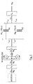
- Fig. 1 shows a schematic representation of an example Powertrain with powershift transmission. It exists from the motor with its own moment of inertia J_M; the converter firmly connected to the motor and its own moment of inertia J_T; after that, two parallel clutches K1 and K2 with their front and subordinate translation levels i_an1, i_ab1 and i_an2, i_ab2 and an output moment of inertia J_A. On Gear change is caused, for example, by pressurization the hydraulic clutch K2 and decrease in pressure the shutdown clutch K1 performed. There is also Possibility of pneumatic or electromagnetic couplings to use.
- both clutches over a long period of time are fully loaded at the same time, because of the different translation a harmful tension; the clutches are operated so that both clutches are released at the same time, no force is transmitted.
- the switching process itself is done by a corresponding Control of corresponding sensors (not shown) taken over, preferably on electronic elements based.
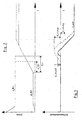
- Fig. 2 shows a representation of clutch pressure on the disengaging clutch when switching the transmission from Fig. 1.
- Die Pressure curve shows the changing during shifting Pressure values p_K1 and p_K2 on the couplings K1 and K2, while in the illustration below according to FIG. 3 the Course of the corresponding differential speed is shown. Is switched with a too short overlap time d_t, 0 (dashed line), this creates a relatively large one "flare", ie a runaway of the turbine speed. At a optimal shifting process results in a differential speed curve according to the solid line at which a slight but present "flare" occurs, which too a pleasant, uninterrupted experience Switching operation leads.
- the circuit is now optimized in such a way that for overlap control of the powershift transmission a map is stored in the control unit, in which a predetermined overlap time d_t between the first and second switching element depending on the am Gearbox applied load is specified in the control unit an optimal overshoot differential speed d_n1, should be stored and the overlap time d_t in Dependence on the current load on the gearbox -
- the directly or by measuring the speed difference between Input and output of the converter must be determined can - iteratively optimize so that the optimal overshoot differential speed (“flare”) d_n1, should set.
- the overlap times determined d_t which is the predetermined optimal overshoot differential speed d_n1
- should approximate, in another, optimized Map are saved and the new values of the Form control for the overlap time d_t.
- the determined overlap times can also be used d_t, which is the predetermined optimal overshoot differential speed d_n1, should approximate the existing map overwrite and thus directly the new values of the control form for the overlap time d_t.
- one includes Overlap control to perform the above Method at least one drive-side input train, a converter turbine, at least a first and a second switching element, each with a coupling element, at least one output-side output train, one Control unit for controlling the switching process, at least a measuring element for detecting the applied load or slip at the converter, a storage unit with a stored map in which a predetermined overlap time d_t between the first and second switching element depending on the contact on the gearbox Load is specified, another memory in which an optimal overshoot difference speed d_n1 should be stored is, and an arithmetic unit, the overlap time d_t depending on the current load on the Gearboxes by iterative optimization so that the optimal overshoot difference speed d_n1, should results.
- a further memory can also be provided, in which the measured overlap times d_t, which the predetermined optimal overshoot difference speed d_n1, should approximate, stored in a further, optimized map and the new specification of the control for the Form overlap time d_t.
- the controller can also be suitable for the measured overlap times d_t, which are the predetermined ones optimal overshoot differential speed d_n1, should approximate overwrite in the existing map and the new control specification for the overlap time d_t form.
- the pressure of the second clutch over ramp up until the second Clutch closes can also be provided to keep the pressure on the first clutch constant, when a pressure level is reached that corresponds to the transmission input torque plus a dynamic moment.
- the second clutch has the full moment of the first clutch taken over, it is observed that the differential speed on the first clutch from positive to passes negative range.
- the switching quality is much better during the synchronizing phase of the circuit.
Landscapes
- Engineering & Computer Science (AREA)
- General Engineering & Computer Science (AREA)
- Mechanical Engineering (AREA)
- Control Of Transmission Device (AREA)
Description
- Fig. 1
- schematische Darstellung eines Antriebstranges mit Lastschaltgetriebe;
- Fig. 2
- Darstellung von Kupplungsdruck an den Kupplungen beim Schaltvorgang;
- Fig. 3
- Darstellung der zum Kupplungsdruck Korrelierten Differenzdrehzahl an der abschaltenden Kupplung.
- J_A
- abtriebsseitiges Trägheitsmoment
- J_M
- Trägheitsmoment des Motors
- J_T
- Trägheitsmoment des Wandlers
- K1
- Schaltkupplung
- K2
- Schaltkupplung
- i_ab1
- Übersetzungsstufe
- i_an1
- Übersetzungsstufe
- i_ab2
- Übersetzungsstufe
- i_an2
- Übersetzungsstufe
- p_K1
- Druckwert an Kupplung K1
- p_K2
- Druckwert an Kupplung K2
- d_t
- Überschneidungszeit
- d_n1
- Überschwingdifferenzdrehzahl
- d_n1,max
- maximale Überschwingdifferenzdrehzahl
- d_n1,soll
- Solldifferenzdrehzahl
- d_n1, neg
- negative Drehzahldifferenz
Claims (9)
- Überschneidungssteuerung eines Lastschaltgetriebes mit:mindestens einem triebseitigen Eingangsstrang;einer Wandlerturbine;mindestens einem ersten und einem zweiten Schaltelement;je einem Kupplungselement pro Schaltelement;mindestens einem abtriebsseitigen Ausgangsstrang;einer Steuereinheit zur Steuerung des Schaltvorganges;mindestens je einem Meßglied zur Erfassung der anliegendenLast und der Eingangsdrehzahl der abschaltenden Kupplung;einer Speichereinheit mit einem abgelegten Kennfeld, in dem eine vorgegebene Überschneidungszeit d_t zwischen dem ersten und zweiten Schaltelement in Abhängigkeit von der am Getriebe anliegenden Belastung angegeben ist, gekennzeichnet durch ein weiteres Meßglied zur Erfassung der Ausgangsdrehzahl der abschaltenden Kupplung;einen weiteren Speicher, in dem eine optimale Überschwingdifferenzdrehzahl d_n1,soll abgelegt ist;eine Recheneinheit, die die Überschneidungszeit d_t in Abhängigkeit von der aktuellen Belastung des Getriebes durch iteratives Optimieren so einstellt, daß sich die optimale Überschwingdifferenzdrehzahl d_n1,soll einstellt.
- Überschneidungssteuerung gemäß Anspruch 1, dadurch gekennzeichnet, daß zur Messung des Lastzustandes mindestens zwei Drehzahlsensoren vorgesehen sind, die die Drehzahldifferenz zwischen Ein- und Ausgang des Wandlers bestimmen.
- Überschneidungssteuerung gemäß einem der Ansprüche 1 bis 2, dadurch gekennzeichnet, daß ein weiterer Speicher vorgesehen ist, in dem die ermittelten Überschneidungszeiten d_t, die die vorgegebene optimale Überschwingdifferenzdrehzahl d_n1,soll annähern, in einem weiteren, optimierten Kennfeld gespeichert werden und die neue Vorgabe der Steuerung für die Überschneidungszeit d_t bilden.
- Überschneidungssteuerung gemäß einem der Ansprüche 1 bis 2, dadurch gekennzeichnet, daß die ermittelten Überschneidungszeiten d_t, die die vorgegebene optimale Überschwingdifferenzdrehzahl d_n1,soll am öffnenden Schaltelement annähern, das bestehende Kennfeld überschreiben und die neue Vorgabe der Steuerung für die Überschneidungszeit d_t bilden.
- Verfahren zur Optimierung einer Überschneidungssteuerung eines Lastschaltgetriebes mit mindestens einem triebseitigen Eingangsstrang, einer Wandlerturbine, mindestens einem ersten und einem zweiten Schaltelement mit je einem Kupplungselement, mindestens einem abtriebsseitigen Ausgangsstrang und einer Steuereinheit mit einem abgelegten Kennfeld, in dem eine vorgegebene Überschneidungszeit d_t zwischen dem ersten und zweiten Schaltelement in Abhängigkeit von der am Getriebe anliegenden Belastung angegeben ist, dadurch gekennzeichnet, daß
in der Steuereinheit eine optimale Überschwingdifferenzdrehzahl d_n1,soll am öffnenden Schaltelement abgelegt ist; die maximale Überschwingdifferenzdrehzahl gemessen wird und mit d_n1, soll verglichen wird; die Überschneidungszeit d_t in Abhängigkeit von der aktuellen Belastung des Getriebes durch iteratives Optimieren so eingestellt wird, daß sich die optimale Überschwingdifferenzdrehzahl d_n1,soll einstellt. - Verfahren gemäß Anspruch 5, dadurch gekennzeichnet, daß der Lastzustand durch die Messung der Drehzahldifferenz zwischen Ein- und Ausgang des Wandlers und durch Auswertung der Leistungsaufnahme- und Drehmomentverstärkungskennlinien des Wandlers bestimmt wird.
- Verfahren gemäß einem der Ansprüche 5 bis 6, dadurch gekennzeichnet, daß die ermittelten Überschneidungszeiten d_t, die die vorgegebene optimale Überschwingdifferenzdrehzahl d_n1,soll annähern, in einem weiteren, optimierten Kennfeld gespeichert werden und die neuen Werte der Steuerung für die Überschneidungszeit d_t bilden.
- Verfahren gemäß einem der Ansprüche 5 bis 6, dadurch gekennzeichnet, daß die ermittelten Überschneidungszeiten d_t, die die vorgegebene optimale Überschwingdifferenzdrehzahl d_n1,soll annähern, das bestehende Kennfeld überschreiben und die neuen Werte der Steuerung für die Überschneidungszeit d_t bilden.
- Verfahren gemäß einem der Ansprüche 5 bis 8, dadurch gekennzeichnet, daß der maximal notwendige Schaltdruck an der zweiten (neuen) Kupplung während der Synchronphase anhand der Differenzdrehzahl an der ersten (alten) Kupplung eingestellt wird.
Applications Claiming Priority (2)
| Application Number | Priority Date | Filing Date | Title |
|---|---|---|---|
| DE19522834 | 1995-06-23 | ||
| DE19522834A DE19522834A1 (de) | 1995-06-23 | 1995-06-23 | Adaptive Lastschaltsteuerung |
Publications (3)
| Publication Number | Publication Date |
|---|---|
| EP0750139A2 EP0750139A2 (de) | 1996-12-27 |
| EP0750139A3 EP0750139A3 (de) | 1999-08-25 |
| EP0750139B1 true EP0750139B1 (de) | 2001-11-21 |
Family
ID=7765085
Family Applications (1)
| Application Number | Title | Priority Date | Filing Date |
|---|---|---|---|
| EP96109655A Expired - Lifetime EP0750139B1 (de) | 1995-06-23 | 1996-06-15 | Adaptive Lastschaltsteuerung |
Country Status (2)
| Country | Link |
|---|---|
| EP (1) | EP0750139B1 (de) |
| DE (2) | DE19522834A1 (de) |
Families Citing this family (4)
| Publication number | Priority date | Publication date | Assignee | Title |
|---|---|---|---|---|
| DE19744100C2 (de) | 1997-10-06 | 1999-08-12 | Zahnradfabrik Friedrichshafen | Verfahren zur Druckadaption einer Überschneidungs-Hochschaltung |
| DE102006002122B4 (de) * | 2006-01-17 | 2018-02-15 | Zf Friedrichshafen Ag | Verfahren zum Betreiben eines Antriebsstranges eines Fahrzeugs |
| JP5031052B2 (ja) | 2010-03-16 | 2012-09-19 | ジヤトコ株式会社 | 自動変速機の制御装置 |
| JP6499129B2 (ja) * | 2016-07-22 | 2019-04-10 | トヨタ自動車株式会社 | 車両の制御装置 |
Family Cites Families (5)
| Publication number | Priority date | Publication date | Assignee | Title |
|---|---|---|---|---|
| DE3436190C2 (de) * | 1984-10-03 | 1995-06-22 | Bosch Gmbh Robert | Einrichtung zur elektronischen Steuerung eines automatischen Fahrzeuggetriebes |
| DE3925524A1 (de) * | 1989-08-02 | 1991-02-07 | Fendt & Co Xaver | Steuerung fuer ein stufengetriebe eines kraftfahrzeuges |
| KR920010906B1 (ko) * | 1989-08-23 | 1992-12-21 | 마쯔다 가부시기가이샤 | 자동변속기의 라인압 제어장치 |
| JP2873615B2 (ja) * | 1990-09-11 | 1999-03-24 | 株式会社ユニシアジェックス | 流体伝動装置付変速機の作動油圧制御装置 |
| US5343782A (en) * | 1992-08-31 | 1994-09-06 | General Motors Corporation | Anti-flare method using offgoing slip speed and rate of change of slip-speed to determine pressure compensation for incoming clutch |
-
1995
- 1995-06-23 DE DE19522834A patent/DE19522834A1/de not_active Withdrawn
-
1996
- 1996-06-15 EP EP96109655A patent/EP0750139B1/de not_active Expired - Lifetime
- 1996-06-15 DE DE59608235T patent/DE59608235D1/de not_active Expired - Fee Related
Also Published As
| Publication number | Publication date |
|---|---|
| DE19522834A1 (de) | 1997-01-02 |
| EP0750139A3 (de) | 1999-08-25 |
| DE59608235D1 (de) | 2002-01-03 |
| EP0750139A2 (de) | 1996-12-27 |
Similar Documents
| Publication | Publication Date | Title |
|---|---|---|
| DE3885403T2 (de) | Erfassen und Ausregeln des Rutsches bei stationärem Lauf für ein Getriebe eines Kraftfahrzeugs. | |
| EP0650564B1 (de) | Getriebeeinheit zur anordnung zwischen einem antriebsmotor und einem verbraucher | |
| DE4114382B4 (de) | Steuer- bzw. Regeleinrichtung für die Schaltung eines Automatikgetriebes | |
| DE102015102001B4 (de) | Fahrzeuggetriebe mit Blockierungsüberwachungslogik | |
| DE60207135T2 (de) | Automatikgetriebe | |
| EP0670789A1 (de) | Verfahren zur steuerung des abtriebsmoments eines automatischen schaltgetriebes | |
| DE102016105262B4 (de) | Getriebekomponentenstörungsdetektion und -vermeidung | |
| DE102016105260A1 (de) | Getriebeeingangsdrehmomentmanagement | |
| DE60006456T2 (de) | Schaltungssteuerung basierend auf den Kupplungsschlupf | |
| EP0545298A1 (de) | Fahrzeugantriebsstrang mit hydraulisch gesteuertem Schaltgetriebe | |
| EP0651182B1 (de) | Verfahren zum Steuern einer die Drehzahldifferenz einer Kupplung eines Kraftfahrzeuges bestimmenden Stellgrösse | |
| DE69019172T2 (de) | Kraftfahrzeug-Antriebssteuerungssystem. | |
| DE19728484A1 (de) | Automatisches Getriebe mit Antikriechsteuerungsapparat | |
| EP0931961B1 (de) | Eichverfahren für Steuerkupplungen eines Getriebes | |
| DE102018205710B4 (de) | Verfahren und Steuerungseinrichtung zum Betreiben eines Antriebsstrangs | |
| DE19750824C2 (de) | Verfahren zur Erfassung einer Grenzstellungsposition einer Kraftfahrzeugkupplung | |
| DE19955799A1 (de) | Einrichtung und Verfahren zum Steuern von Automatikgetrieben | |
| DE102004022667B4 (de) | Verfahren zur Steuerung einer Schubrückschaltung | |
| EP0750139B1 (de) | Adaptive Lastschaltsteuerung | |
| EP1437520A2 (de) | Verfahren zum Steuern einer automatisch betätigten Kupplung | |
| DE112019001201T5 (de) | Verfahren zum bestimmen mindestens eines schaltparameters eines fahrzeuggetriebes | |
| WO2001098677A2 (de) | Verfahren und vorrichtung zum kompensieren des einflusses der drehzahl auf die kennlinie einer kupplung | |
| DE10338623B4 (de) | Verfahren zur Erhöhung der Güte eines Drehmomentschätzwerts und Verfahren zum Betrieb eines Antriebsstrangs eines Kraftfahrzeugs | |
| WO2017088855A1 (de) | Verfahren zur abtriebsneutralen lastschaltung von automatgetrieben | |
| DE19544792A1 (de) | Gangschaltsteuervorrichtung |
Legal Events
| Date | Code | Title | Description |
|---|---|---|---|
| PUAI | Public reference made under article 153(3) epc to a published international application that has entered the european phase |
Free format text: ORIGINAL CODE: 0009012 |
|
| AK | Designated contracting states |
Kind code of ref document: A2 Designated state(s): DE FR IT |
|
| PUAL | Search report despatched |
Free format text: ORIGINAL CODE: 0009013 |
|
| AK | Designated contracting states |
Kind code of ref document: A3 Designated state(s): DE FR IT |
|
| 17P | Request for examination filed |
Effective date: 19990930 |
|
| RTI1 | Title (correction) |
Free format text: ADAPTIVE SHIFT CONTROL |
|
| GRAG | Despatch of communication of intention to grant |
Free format text: ORIGINAL CODE: EPIDOS AGRA |
|
| 17Q | First examination report despatched |
Effective date: 20010228 |
|
| GRAG | Despatch of communication of intention to grant |
Free format text: ORIGINAL CODE: EPIDOS AGRA |
|
| GRAH | Despatch of communication of intention to grant a patent |
Free format text: ORIGINAL CODE: EPIDOS IGRA |
|
| GRAH | Despatch of communication of intention to grant a patent |
Free format text: ORIGINAL CODE: EPIDOS IGRA |
|
| ITF | It: translation for a ep patent filed | ||
| GRAA | (expected) grant |
Free format text: ORIGINAL CODE: 0009210 |
|
| AK | Designated contracting states |
Kind code of ref document: B1 Designated state(s): DE FR IT |
|
| REF | Corresponds to: |
Ref document number: 59608235 Country of ref document: DE Date of ref document: 20020103 |
|
| ET | Fr: translation filed | ||
| PLBE | No opposition filed within time limit |
Free format text: ORIGINAL CODE: 0009261 |
|
| STAA | Information on the status of an ep patent application or granted ep patent |
Free format text: STATUS: NO OPPOSITION FILED WITHIN TIME LIMIT |
|
| 26N | No opposition filed |
Opponent name: RENAULT S.A.S. |
|
| PG25 | Lapsed in a contracting state [announced via postgrant information from national office to epo] |
Ref country code: DE Free format text: LAPSE BECAUSE OF NON-PAYMENT OF DUE FEES Effective date: 20030101 |
|
| PG25 | Lapsed in a contracting state [announced via postgrant information from national office to epo] |
Ref country code: FR Free format text: LAPSE BECAUSE OF NON-PAYMENT OF DUE FEES Effective date: 20030228 |
|
| REG | Reference to a national code |
Ref country code: FR Ref legal event code: ST |
|
| PG25 | Lapsed in a contracting state [announced via postgrant information from national office to epo] |
Ref country code: IT Free format text: LAPSE BECAUSE OF NON-PAYMENT OF DUE FEES;WARNING: LAPSES OF ITALIAN PATENTS WITH EFFECTIVE DATE BEFORE 2007 MAY HAVE OCCURRED AT ANY TIME BEFORE 2007. THE CORRECT EFFECTIVE DATE MAY BE DIFFERENT FROM THE ONE RECORDED. Effective date: 20050615 |